NovaTec NovaWheel NWB Series User manual

NWB& NWB-HC Series, With NovaTouch™
Monochrome 4” Touch Panel PLC
MODELS -25 through -200
Document: NWB & NWB-HC IM 28 OCT 2014
NWB-50
©NOVATEC, Inc. 2014 All Rights Reserved
NWB-50-HC

NWB & NWB-HC IM28 OCT 2014 Page 2
Instruction Manual NWB & NWB-HC IM 28 OCT 2014
NOTES:
Please record the following
information, which is specific to this
piece of equipment, in the space
provided. Our Parts/Service
Department will need these numbers
to properly respond to any of your
requests.
Instruction Manual: NWB & NWB-HC IM 28 OCT 2014
Model #:________
Serial #________
DISCLAIMER: NOVATEC, Inc. shall not be liable
for errors contained in this Instruction Manual nor
for misinterpretation of information contained
herein. NOVATEC shall not, in any event, be held
liable for any special, indirect or consequential
damages in connection with performance or use of
this information.

NWB & NWB-HC IM28 OCT 2014 Page 3
Instruction Manual NWB & NWB-HC IM 28 OCT 2014
Table of Contents
1.0 SALES AND SERVICE....................................................................................................4
2.0 SHIPPING AND INSPECTION.........................................................................................4
3.0 PRINCIPLE OF OPERATION ..........................................................................................5
4.0 PRODUCT FAMILIARIZATION........................................................................................6
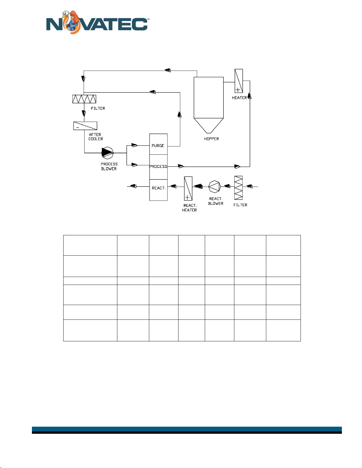
4.1 System Flow Diagram ......................................................................................................7
4.2 Specifications –NovaWheel™ Dryer...............................................................................7
5.0 INSTALLATION...............................................................................................................8
5.1 Location ...........................................................................................................................8
5.2 Customer Piping Connections..........................................................................................8
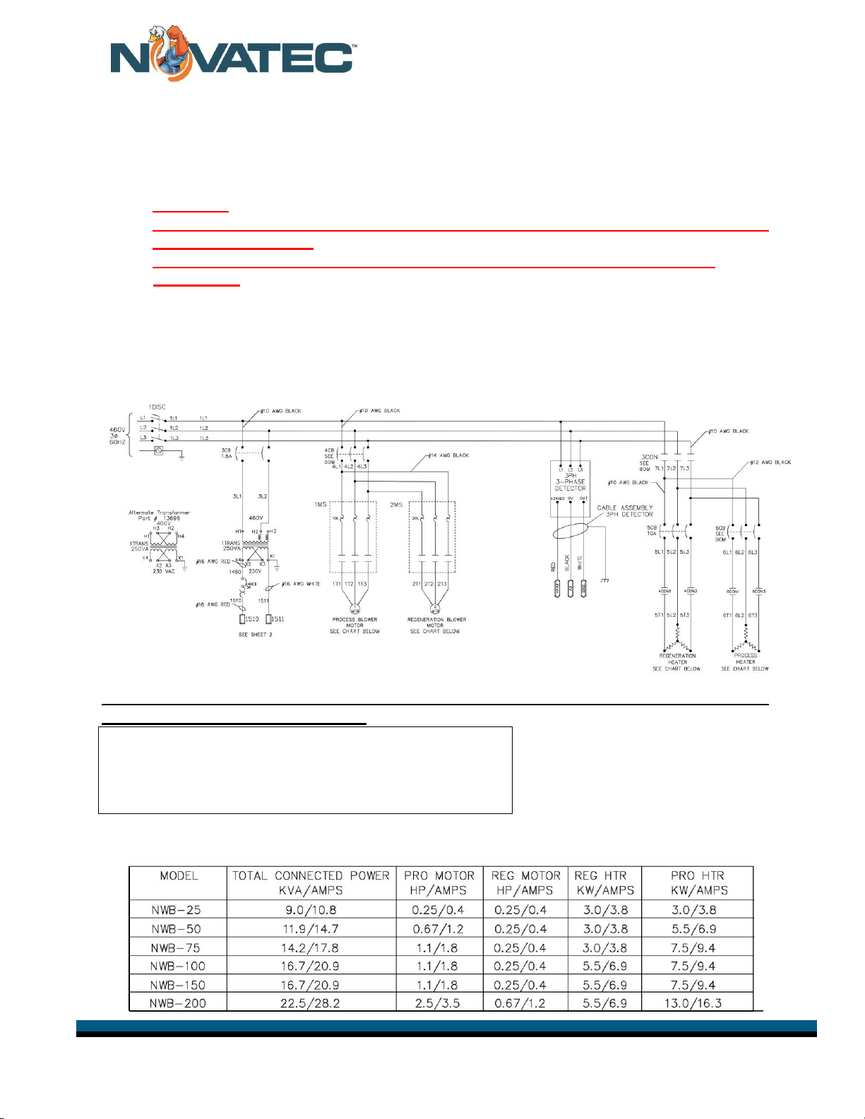
5.3 Electrical Connections......................................................................................................9
5.4 Cooling Coil Connection.................................................................................................10
6.0 FUNCTION CONTROLS................................................................................................11
6.1 Process Temperature Control (Drying Temperature).......................................................11
6.2 Regeneration Temperature Control.................................................................................11
6.3 Process & Regeneration Air Filter Pressure Switches (Ps).Error! Bookmark not defined.
6.4 Process Air Dew Point Monitor........................................................................................11
6.5 Intelligent Regeneration ..................................................................................................11
7.0 PRE-OPERATING SYSTEM CHECK.............................................................................12
7.1 Starting The Dryer...........................................................................................................12
7.2 Checking Electrical Phase...............................................................................................12
8.0 NovaTouch™ CONTROL..............................................................................................13
8.1 System Conventions: ......................................................................................................13
8.3 Explanation of Password Levels......................................................................................15
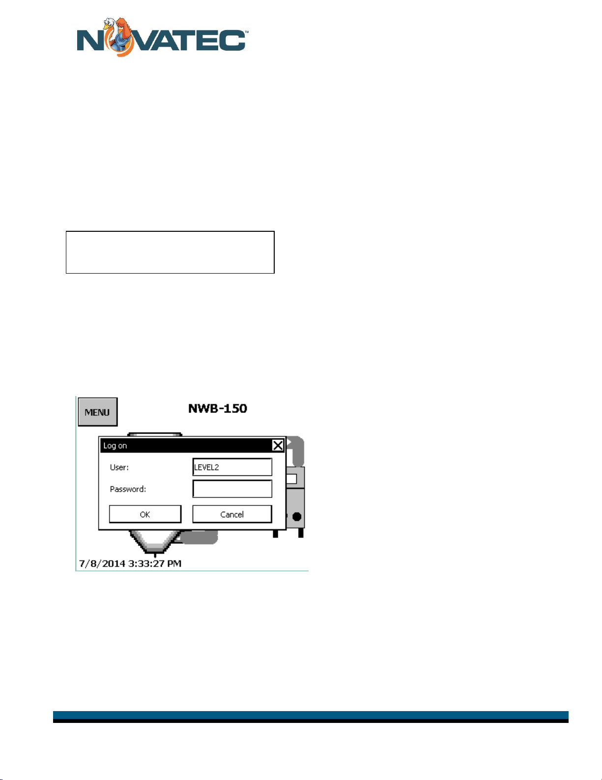
8.4 Initial Logon.....................................................................................................................15
9.1 Clock Setup......................................................................................................................16
9.2 Auto Start Setup...............................................................................................................16
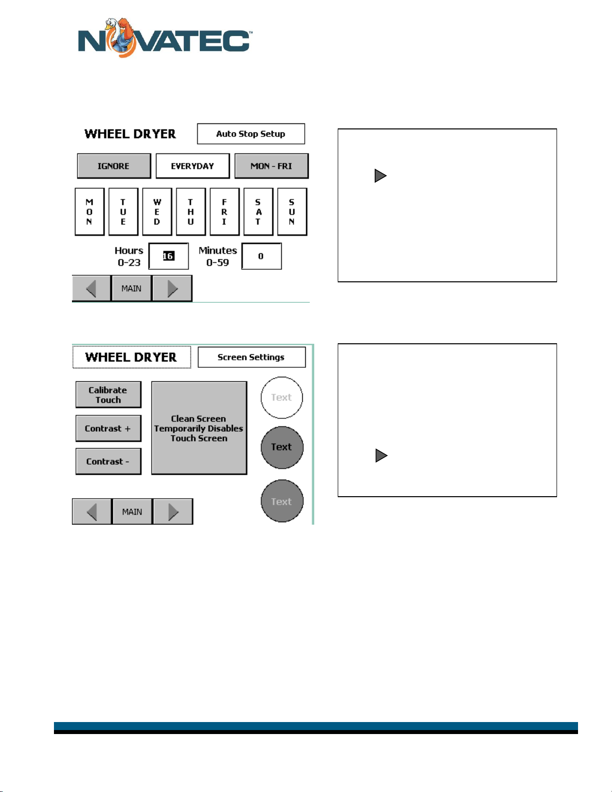
9.3 Auto Stop Setup...............................................................................................................17
9.4 Touch Screen Adjustments ..............................................................................................17
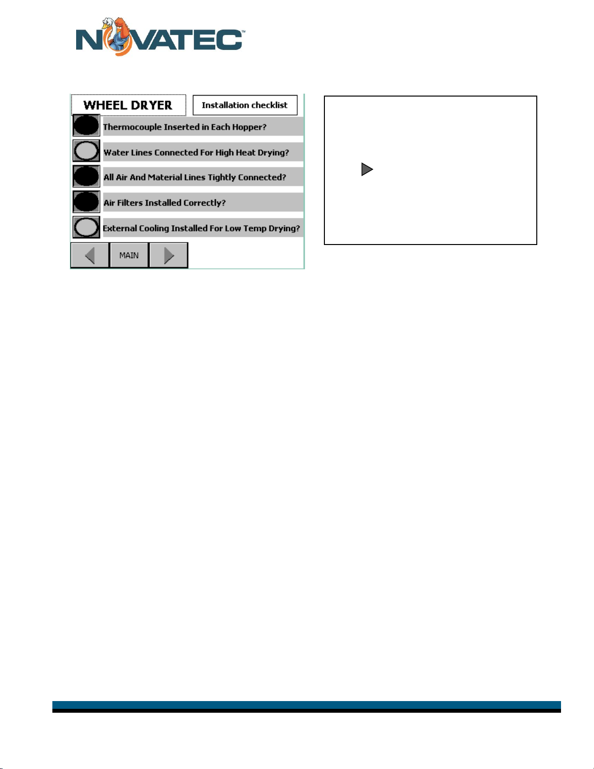
9.5 Installation Checklist.........................................................................................................18
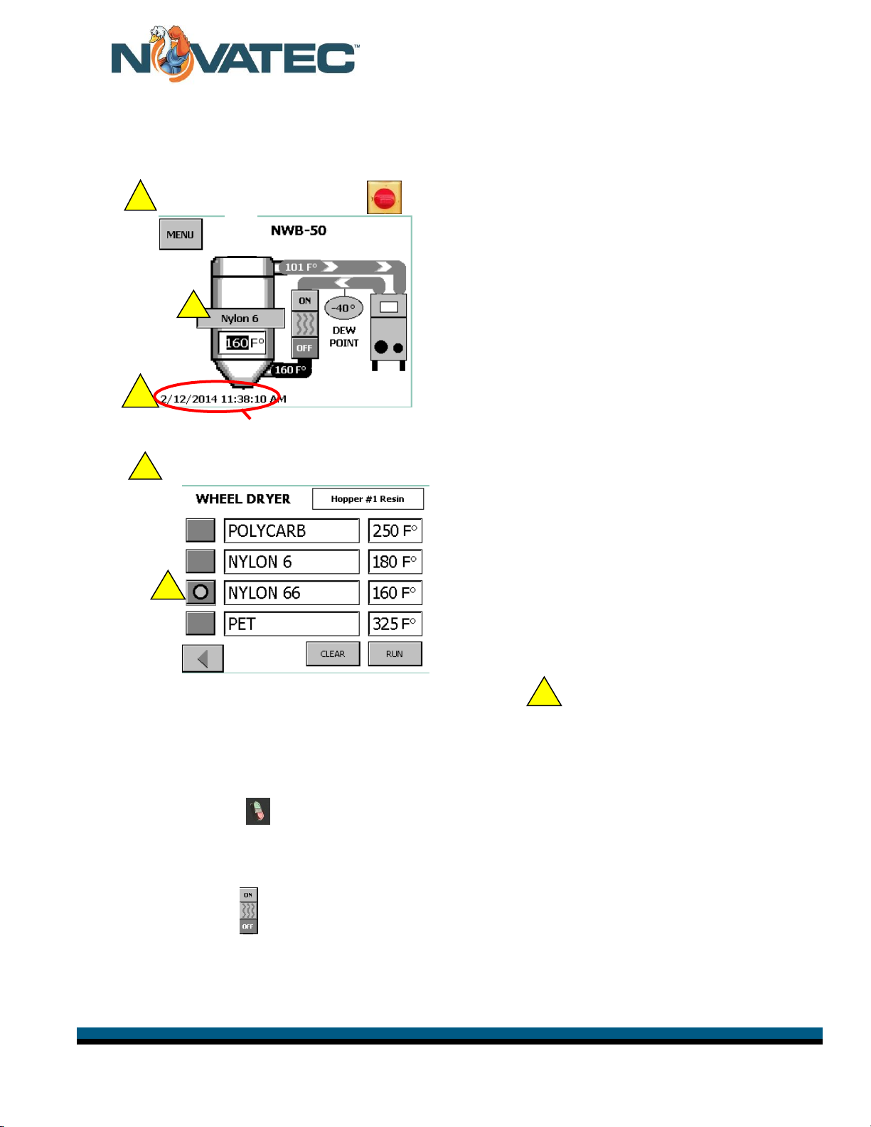
10.0 DRYING MATERIAL......................................................................................................19
11.0 ADVANCED FUNCTIONS..............................................................................................20
11.1 Advanced Functions And Options Screen (Level 2 or higher).........................................20
11.2 Dryer Alarms (Level 3) ...................................................................................................21
11.3 Dryer Status (Widely Used By processors).....................................................................21
12.0 MESSAGE SCREEN ALARMS .....................................................................................22
13.0 MAINTENANCE INSTRUCTIONS .................................................................................23
13.1 Suggested Maintenance Schedule*................................................................................23
13.2 Process and Regeneration Filters .................................................................................24
13.3 Draining Plasticizer........................................................................................................24
13.4 Chain and Sprockets.....................................................................................................25
13.5 Desiccant Rotor..............................................................................................................25
13.6 Motor Rotation Signal....................................................................................................26
13.7 Rotor Replacement .......................................................................................................26
13.8 Seal Replacement.........................................................................................................27
13.9 Drive Motor Replacement..............................................................................................27
13.10 Seal Replacement........................................................................................................28
13.11 Drive Motor Replacement............................................................................................28
13.12 Motor Rotation Signal..................................................................................................28
14.0 TROUBLE SHOOTING and ERROR MESSAGES.......................................................29
15.0 WARRANTY –NOVATEC, INC. - Effective Date 6-12-2012.........................................31

NWB & NWB-HC IM28 OCT 2014 Page 4
Instruction Manual NWB & NWB-HC IM 28 OCT 2014
FOREWORD
This manual is dedicated to the principle that any engineered system will have many elements
contributing to the smooth operation of the systems, and that these must be understood in order
that installation and operation can proceed successfully. The electrical and mechanical
components in the NWB Series dryers have been manufactured, selected and assembled with
care to give you excellent service. A wide range of NWB series dryers have been introduced to
enable our valued customers to select the right model for their application. This NWB series
dryer has been designed for use in closed loop resin drying systems. All components of your
NWB series dryers have been carefully engineered and manufactured and have been thoroughly
inspected for quality, function and performance. Before installing this system, please read this
manual, review the diagrams and the safety information. This should save valuable installation
and operation time later and will help ensure safe operation and long life.
1.0 SALES AND SERVICE
NOVATEC maintains qualified sales, engineering, and service personnel to assist in any
way possible. If you have any questions concerning the types of equipment which
NOVATEC manufactures that might improve your process, or any questions concerning
service, we urge you to contact us.
Sales: 1-800-BEST-DRY ●1-800-237-8379 ●Fax: 410-789-4638 ● Sales@novatec.com
Technical Service Department: 1-800-938-6682 ● Service@novatec.com
2.0 SHIPPING AND INSPECTION
Although NOVATEC uses reputed carriers to deliver products, it has no control over the
product once it leaves the manufacturing facility. Upon receiving the product, thoroughly
inspect all equipment inside and out for damage that may have occurred during shipment.
If any damage is found, a claim should be filed immediately with your carrier.
NOVATEC thoroughly tests and inspects all products before shipment. You are to make
the piping, and electrical connections for final installation and commissioning. If there any
problems, shut down the equipment and contact the NOVATEC Technical Service
Department.

NWB & NWB-HC IM28 OCT 2014 Page 5
Instruction Manual NWB & NWB-HC IM 28 OCT 2014
3.0 PRINCIPLE OF OPERATION
The NWB NovaWheel™Series dryer was engineered and designed to effectively remove
moisture (in the vapor state) from hygroscopic plastic resins. This process is
accomplished by the continuously rotating desiccant wheel and the three air streams
(Process, Purge and Regeneration). The Process return air is exposed to an adsorbing
media (desiccant wheel) in a sealed air stream, where the desiccant adsorbs the
moisture from process air. After the desiccant has adsorbed the moisture, it is exposed to
a Regeneration air stream which has been pre-heated to a temperature of about 380°F,
(190°C). This causes the moisture to be driven out from the desiccant and prepares it for
more moisture adsorption. Now the desiccant media passes through third air stream
called purge air stream. Here the desiccant media is cooled down by some of the process
air before entering back into the process to provide for better performance. The three air
streams (process, regeneration and purge) are separated by special Teflon fabric coated
silicon seals. The process air and regeneration air is compressed by using regenerative
blowers.
The dry air from the dryer is then is heated and the air temperature is controlled in an
electric heater, located either in the NovaWheel cabinet on the smaller sizes or this
heater is located at the drying hopper on larger sizes or on a central drying system with
more than one hoppers. The hot dry air enters the hopper at the bottom and dries the
resin in the hopper. The air from the top of the hopper is returned to the dryer, where it is
filtered, cooled in a cooling coil and the process blower sends the air back to the dryer
again to be dried.

NWB & NWB-HC IM28 OCT 2014 Page 6
Instruction Manual NWB & NWB-HC IM 28 OCT 2014
4.0 PRODUCT FAMILIARIZATION
The major components and their locations are shown below.
DRIVEN SPROCKET
Process
Filter
(5 micron)
Regeneration
Filter
Filter
Regeneration
Blower
Filter
Regeneration
Air Outlet
Return Air
From Hopper
Touch Screen
Control
Process Air
To Hopper
Hopper
In
Out
Desiccant
Wheel
Desiccant
Wheel
Drive Motor
Alarm Light
Cooling Water
Chain
Sprocket &
Idler Bracket
Chain
Sprocket &
Idler Bracket
Process
Blower
Filter
Electrical
Panel
Plasticized
Drain
Internal
Pre-Cooler

NWB & NWB-HC IM28 OCT 2014 Page 7
Instruction Manual NWB & NWB-HC IM 28 OCT 2014
4.1 System Flow Diagram
4.2 Specifications –NovaWheel™Dryer
Model
NWB or
NWB-HC
-25
NWB or
NWB-HC-
50
NWB or
NWB-DC
-75
NWB or
NWB-HC
-100
NWB or
NWB-HC
-150
NWB or
NWB-HC
-200
Max Material Flow -
Lbs./Hr
Kg/Hr
25
11
50
23
75
34
100
46
150
75
200
91
Voltage –Phase - Hz
460-3-60
460-3-60
460-3-60
460-3-60
460-3-60
460/3/60
Water Required -
Nominal (GPM):
.25
.5
.75
1.0
1.5
3.0
Customer Water Line
Size (min):
1/2” OD
(13 mm)
1/2” OD
(13 mm)
1/2” OD
(13 mm)
1/2” OD
(13 mm)
1/2” OD
(13 mm)
1/2”
(13 mm)
Wheel Speed -
Nominal
(revolutions per hr.):
≤10
≤10
≤10
≤10
≤10
≤10
Process Air dew Point (nominal): -40ºF (-40°C)
Drying Temperature: 150-350°F (66-177°C)

NWB & NWB-HC IM28 OCT 2014 Page 8
Instruction Manual NWB & NWB-HC IM 28 OCT 2014
5.0 INSTALLATION
CAUTION: FOLLOW ALL NATIONAL AND LOCAL ELECTRICAL AND MECHANICAL
CODES, AS REQUIRED. ONLY QUALIFIED AND TRAINED PERSONNEL
SHOULD INSTALL AND OPERATE THIS EQUIPMENT.
5.1 Location
Locate your NWB Series dryer in a low traffic area, this will avoid disturbance of the
hoses connecting your dryer to the hopper. Allow sufficient distance (at least 2 feet) from
the surrounding equipment, so the access doors may be opened to perform routine
maintenance on the dryer and for safe operation.
There must be a grounded power source that will supply the correct voltage per the dryer
nameplate.
Water (tower or chilled at +45 to 85°F) must be supplied to the cooling coil using flexible
hoses.
5.2 Customer Piping Connections
Care should be taken while connecting the process air piping. If hoses are used, it should
suitable for at least 350°F and silicone hose is recommended. On larger piping, hard
piping with steel tubing should be considered. The piping should not block the access
doors of the dryer. See below for the correct connection size from the dryer to the
hopper.
Process air connections:
NWB-25: 2 inches diameter
NWB-50: 2 inches diameter
NWB-75: 2 inches diameter
NWB-100: 4 inches diameter
NWB-150: 4 inches diameter
NWB-200: 4 inches diameter
NOTE:
On smaller hoppers, we introduce the
process air about midway up the
hopper and pipe it down to the bottom
of the hopper through a diffuser cone
that spreads to heat evenly.

NWB & NWB-HC IM28 OCT 2014 Page 9
Instruction Manual NWB & NWB-HC IM 28 OCT 2014
5.3 Electrical Connections
The NWB Series dryer comes from the factory with all control circuits wired and the dryer
needs to be connected to the proper power source.
CAUTION:
All electrical connections must be made by qualified electricians, per national and
local electrical codes.
Disconnect and lock out the main power source before making the electrical
connection.
Procedure:
1) Turn disconnect on the door to the “OFF” position, lock out the main power source and
open the electrical enclosure.
2) Per the electrical diagram, install the main power wire to the main disconnect switch
holder and install the ground wire.
Full size electrical drawings are included with this Instruction package for the
voltage of the dryer you ordered.
NOTE: Please make sure that all electrical connections are tight. It is not common but a
loose connection is possible after a long truck ride.
NOTE: 3 Phase detection is included on this model.
If the connection is not correct, a pop-up alarm will
appear on the touch screen upon startup. You
should immediately correct this condition.

NWB & NWB-HC IM28 OCT 2014 Page 10
Instruction Manual NWB & NWB-HC IM 28 OCT 2014
5.4 Cooling Coil Connection
A Cooling Coil is installed in NWB series dryers and is required to lower the hopper return
temperature when drying temperatures are above 225° F. This increases the efficiency
of dryer.
Tower, city or chilled water is required at between 40 to 85°F. Connect the cooling water
supply and return using flexible hose that is at least 2 feet long, to allow for easy removal
of the cooling coil for cleaning. The water flow rates and the required customer
connection sizes for different models are shown on page 7.
The process airstream must be connected to an external cooling coil if the drying
temperature is below 170°F. Contact Factory for Options.
:
Water Connections
Plasticizer Drain
Plasticizer Drain
Process Air
Connection
Entry Point for Power
NOTE: Use ½” O.D. water hose to get proper flow.
Regeneration
Air Outlet
Unused
Connections
Hopper Return
Air Connection
Alarm Light

NWB & NWB-HC IM28 OCT 2014 Page 11
Instruction Manual NWB & NWB-HC IM 28 OCT 2014
6.0 FUNCTION CONTROLS
The NWB Series dryers come complete with the following controls:
6.1 Process Temperature Control (Drying Temperature)
The Temperature Control is a part of the NovaWheel NovaTouch PLC controller and
controls the process outlet temperature as per the set value. In addition, there is a
process high temperature limit thermostat that is provided for extra safety. (Refer to the
controller section).
6.2 Regeneration Temperature Control
The regeneration temperature is controlled by the NovaTouch PLC controller. In addition,
there is a regeneration high temperature limit thermostat, which provides extra safety.
The regeneration temperature is set at about 380°F. (190°C) and should not be changed.
6.3 Process & Regeneration Air Filter Pressure Switches (PS)
The air pressure differential across the process filter and the regeneration filter is monitored
and the NovaTouch display will alarm and show when a filter needs to be cleaned or
replaced.
These are factory set but often need to be adjusted in the field once the customer loads
resin in the hopper.
Access pressure switches after opening the side panel of
the dryer. Remove Phillips screw that holds clear cover in
place (Fig. 1). Turn knob clockwise or counter-clockwise
to either increase or decrease.
6.4 Process Air Dew Point Monitor
It measures the process air dew point from the dryer.
6.5 Intelligent Regeneration
Intelligent Regen constantly monitors the regeneration inlet and outlet temperatures and
controls them to optimize the energy and dew point performance of the dryer.
Process Filter Pressure Switch
Regen Filter Pressure Switch
Fig. 1

NWB & NWB-HC IM28 OCT 2014 Page 12
Instruction Manual NWB & NWB-HC IM 28 OCT 2014
7.0 PRE-OPERATING SYSTEM CHECK
Once material, water and electrical connections are made, the NWB Series dryer should
be given a final checkout.
7.1 Starting The Dryer
Turn the main disconnect switch to “ON” position to power the dryer. The Main Menu will
appear. To start the dryer depress the “ON/OFF” button on the controller.
The blowers and heaters are now energized and the desiccant wheel will begin turning
and start to dry the return air. It will take several minutes and a couple revolutions of
the wheel, for the dew point to get down to the -40° dew point.
7.2 Checking Electrical Phase
Your NOVATEC NWB Dryer includes Phase Detection. This is particularly
important for dryers that may be moved around the plant. When you turn the MAIN
Disconnect switch to the ON position, a Pop-Up Alarm will appear on the screen if
the connection is not correct. You should immediately correct this condition.
WARNING:
Any wiring procedure should only be done by a qualified electrician familiar with three
phase electrical wiring.

NWB & NWB-HC IM28 OCT 2014 Page 13
Instruction Manual NWB & NWB-HC IM 28 OCT 2014
8.0 NovaTouch™ CONTROL
8.1 System Conventions:
All information and data displays will appear two dimensional in configuration and
flat. All data entry points or operational features will appear three dimensional in
configuration and raised or depressed in appearance depending on their
operational position.
Proceed as follows:
1. Touch the relevant IO field on the screen.
The numerical screen keyboard opens and displays the current value.
2. Set the value.
You can only operate keys which are visualized in 3D format. The type of
value to be entered determines whether a key is enabled or disabled.
The following options for entering values are available:
The current value is deleted when you enter the first character. Enter the value
again.
Use the and keys to move the cursor within the current value. You can
now edit the characters of the current value or add characters.
Use the key to delete the character to the left of the cursor.
Use the key to change the sign of the value.
Select to view the info text of the IO field.
Select to confirm your entries or cancel them with . Both actions
close the screen keyboard.
Numerical Entries: When you touch an IO
field on the HMI device touch screen that
requires only a numerical entry (Password,
Temperature, number of seconds etc.) the
following keyboard will appear.
Alpha/Numeric Entries:
When you are prompted to enter alphabetical
and numerical data (Resin Names/Numbers)
this screen will appear:

NWB & NWB-HC IM28 OCT 2014 Page 14
Instruction Manual NWB & NWB-HC IM 28 OCT 2014
Multiple choice inputs will use the DOWN arrow to alert you to a drop down
menu. Pressing the associated display window will cause the drop down menu to appear.
The keyboard is automatically hidden again when input is complete.
The condition of a switch or display will be displayed in both language and the international
ON/OFF icon.
Example: or
“[?]” or an may appear on any screen, or in any alarm message. This is the indication that
there is additional information available. By pressing the symbol, an information page will appear
on the screen. The information page will be removed by pressing the X in the upper right hand
corner of the page.
Each time you exit a screen via the touch pad, the PLC EEPROM is programmed with the
new information. The exception to this function is the Real Time Clock.
Other symbols will include: Automatic start is on. Automation 2nd set point is on.
Language on screen is U.S. English as indicated on Main menu by en-US.
The alarm icon will appear on any screen when the dryer is in an alarm
condition. The numeral shows how many alarms are active. An “ !”
indicates that the alarm has been acknowledged/cleared. When the icon is
pressed, an explanation will be displayed. If a “ ?“ appears at the end of
the explanation, press it for further details.
8.2 Function Keys Under Control Screen
ON
OFF
There are 4 FUNCTION buttons under each screen.
Pressing these buttons allows the following:
F1= HOME screen
F2 = Logon
F3 = Log Off
F4 = Acknowledges an Alarm

NWB & NWB-HC IM28 OCT 2014 Page 15
Instruction Manual NWB & NWB-HC IM 28 OCT 2014
8.3 Explanation of Password Levels
User name and Password factory defaults (below) should be updated to ensure proper access.
Level1 : 1111(Operator) –
Can choose pre- set recipe and run it.
Level2 : 2222 (Production Supervisor) –level1 plus can change recipes, set clock,
Level3 : 3333 (Maintenance) level 2 plus make entries on Welcome screen, Auto Start/Stop,
Maintenance Screens & Advanced Functions.
setup : Machine Configuration –Factory Pre-sets (NOVATEC Only)
8.4 Initial Logon
Press F2 shown on previous page to Logon and set machine up.
A screen will appear that allows you to choose a password level.
Logon as Level 3 by entering 3333 in the numeric pop-up screen that will appear.
Level 3 can change other user’s passwords
Level 2 can change Level 2 passwords
Level 1 can change Level 1 passwords

NWB & NWB-HC IM28 OCT 2014 Page 16
Instruction Manual NWB & NWB-HC IM 28 OCT 2014
9.0 INITIAL STARTUP
9.1 Clock Setup
9.2 Auto Start Setup
NOVATEC
MENU
Only UPON initial startup will this group
of screens appear. Only UPON initial
startup will this group of screens appear.
They will walk you through the initial
setup of the dryer.
The first screen displays the dryer model
number.
It also gives you the opportunity to
choose whether temperatures will be
displayed in F or C.
Level 2 or higher password required.
Check the time and date pre-sets. If they
are not correct press each incorrect
button. A screen will appear where you
can enter the correct numerical values.
Press after each entry is complete.
Press Day of Week and Daylight Savings
Time for a dropdown box and make your
Choice. Press for next scree.
You may press IGNORE and if you do
not use this function. If you want to set up
the AutoStart function, choose the days of
the week you want to include and press the
hours and minutes buttons to enter (on the
pop-up screen) the times you want the
dryer to start automatically and press
after each entry. The times are entered as
a 24–hour clock.
Press to advance to the Auto Stop
Screen.

NWB & NWB-HC IM28 OCT 2014 Page 17
Instruction Manual NWB & NWB-HC IM 28 OCT 2014
9.3 Auto Stop Setup
9.4 Touch Screen Adjustments
Set this screen up in the same manner as
you did with the Auto-Start function.
Press to advance to the Touch Screen
Adjustments screen
Use this screen to customize the screen
calibrations to suite your operators and
lighting conditions.
This screen should also be used when
the screen needs to be cleaned so that
settings are not accidentally changed.
Press to advance to the Installation
Checklist

NWB & NWB-HC IM28 OCT 2014 Page 18
Instruction Manual NWB & NWB-HC IM 28 OCT 2014
9.5 Installation Checklist
It is important to review each of these
items to ensure that your dryer is
connected properly before starting to dry
material.
Press to access Setup Options where
you can make changes to entries you
have already made OR press MAIN to go
the QuickOp screen.

NWB & NWB-HC IM28 OCT 2014 Page 19
Instruction Manual NWB & NWB-HC IM 28 OCT 2014
1
10.0 DRYING MATERIAL
NOTE: Assure voltage, connection and phasing are correct, cooling water
is supplied (for dying over 225°F) and thermocouple is inserted in hopper.
Connect material source to Hopper Receiver.
Turn Main Disconnect Switch to “ON” position and Quick Op
screen (below) will appear.
Check the Time pre-sets. See page 16 of manual if they are not correct.
It is important that alarms have correct date & time stamp.
Press the RESIN NAME button on the hopper icon to access the resin menu.
Level 1 operator can choose one of the pre-set resins and press RUN to enter those
values in the Quick Op screen. Level 2 or higher can press the resin name and/or drying
temperature and enter new values in the resin memory. The same numeric or
alpha/numeric screens will appear for your entries. Press the BACK button to return to
the Quick Op screen.
After the Drying Hopper is at least 1/2 full of resin, you can start the Process heater.
Press Green “ON” switch to start the Process Heater.
It usually takes 2-4 hours for first hopper load of material to be sufficiently dry for
processing.
Note that Process Heater can be turned OFF or ON by a Level 2 or higher person
using the button in the center of the Quick Op screen.
Pressing MENU on the Quick Op screen will allow viewing of the ADVANCED
FUNCTIONS screen
v
v
6
4
4
v
2
v
3
7
3

NWB & NWB-HC IM28 OCT 2014 Page 20
Instruction Manual NWB & NWB-HC IM 28 OCT 2014
Press MENU on Quick Op Screen
From here you can access:
ADVANCED FUNCTIONS (see 11.1)
CONTROL SETUP
(Returns to Welcome screen with access
to setup screens 9.0)
USER PASSWORDS (See 11.4)
DRYER STATUS (see 11.3)
You can also return to the Quick Op screen
11.0 ADVANCED FUNCTIONS
11.1 Advanced Functions And Options Screen (Level 2 or higher)
Status
View
OverDry Protection is typically
used to ensure the nylons and
other moisture sensitive resins
are not over dried.
Water Saver can be employed
when a external cooling coil is
being used.
Alarm Settings button opens up
the screen show in 11.2
This manual suits for next models
13
Table of contents
Other NovaTec Dryer manuals