NovaTec NovaWheel NWDC Series User manual

NovaWheel™ Dry-Convey Dryers
NWDC –Series, With NovaTouch™ Touch Panel PLC
MODELS NW-25NC-DC through NW-150NC-DC)
CRITICAL INFORMATION:
Please see Technical Bulletin
on Page 2 of this Instruction Manual
© 2013 NOVATEC, Inc. All Rights Reserved Instruction Manual NWDC IM 26 MAR 2014
NWDC IM 26 MAR 2014 © 2014 Novatec, Inc. All Rights Reserved Page 2 [Type text] [Type text]
NWDC IM 26 MAR 2014
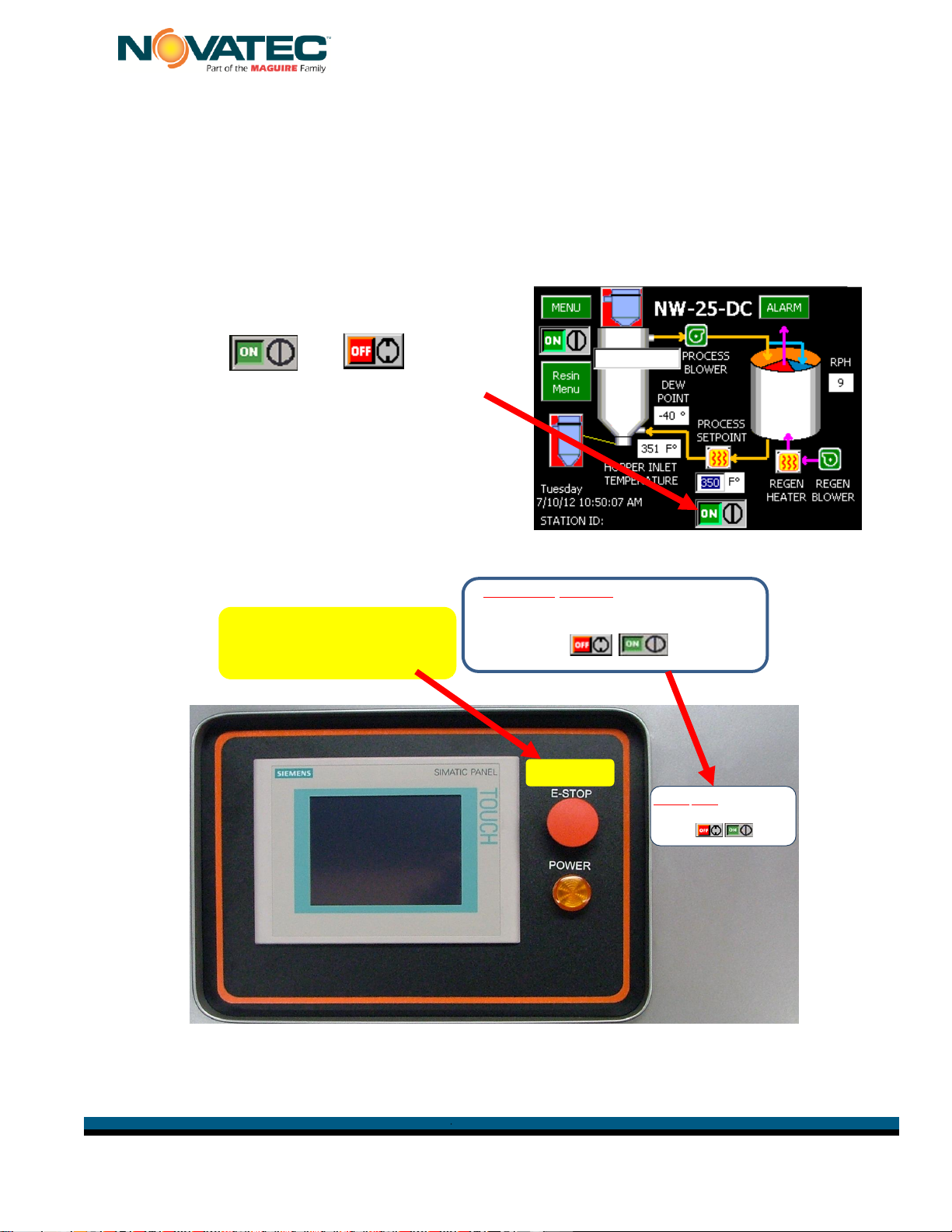
EMERGENCY USE
ONLY
WARNING: DO NOT turn dryer OFF with
EMERGENCY STOP.
Turn dryer ON & OFF at bottom of touch
screen with button.
CRITICAL TECHNICAL BULLETIN
It has come to our attention that operators of NWDC dryers are sometimes, mistakenly
using the EMERGENCY STOP button to routinely turn these dryers “OFF”.
EMERGENCY STOP should ONLY be used under TRUE EMERGENCY conditions.
Repeated use of EMERGENCY STOP can cause dryer component failure.
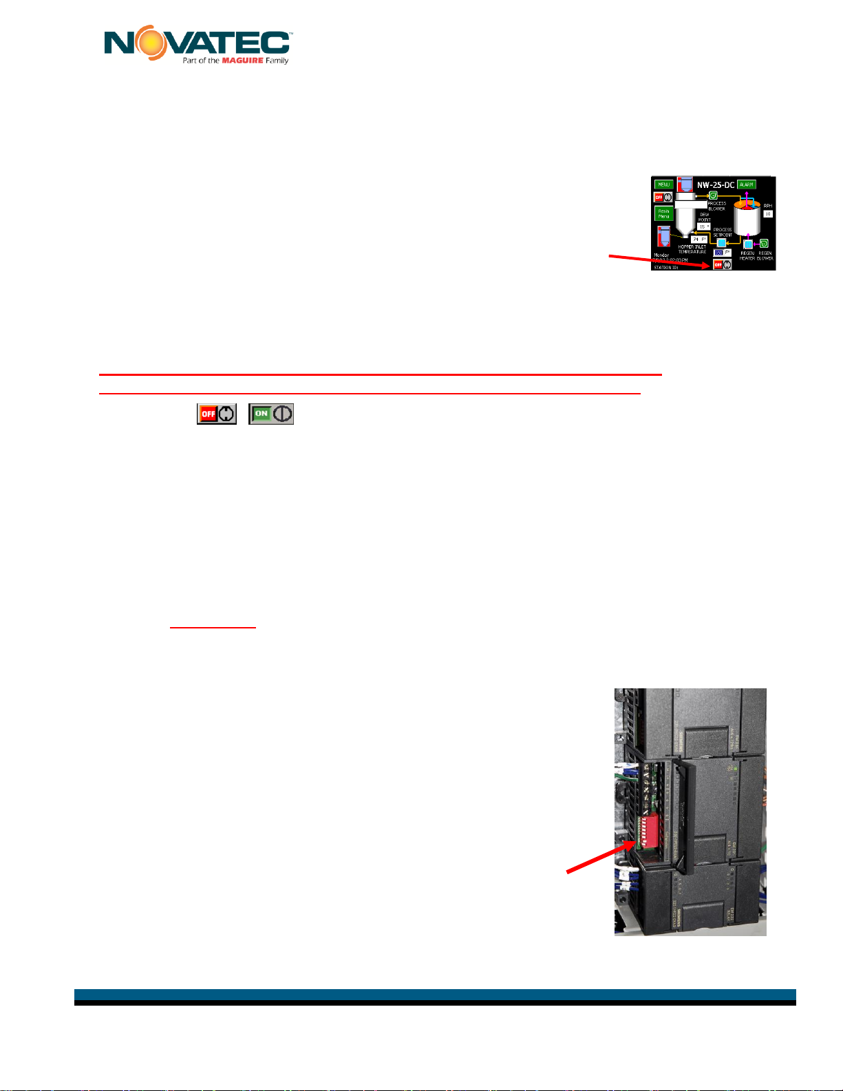
These dryers are intended to be turned “ON” and
“OFF” on the touch screen control panel by
pressing the or button
located at the bottom of the QuickOp screen.
We have added labels to the control panel to
remind operators how the dryer should be turned
on and off but please make sure they understand
the importance of these instructions to avoid
component failure and production interruptions.
WARNING: DO NOT turn dryer OFF with
EMERGENCY STOP.
Turn dryer ON & OFF at bottom of touch
screen with button.
EMERGENCY
USE ONLY

NWDC IM 26 MAR 2014 © 2014 Novatec, Inc. All Rights Reserved Page 3 [Type text] [Type text]
NWDC IM 26 MAR 2014
NOTES:
Please record the following
information, which is specific to
this piece of equipment, in the
space provided. Our Parts/Service
Department will need these
numbers to properly respond to
any of your requests.
Instruction Manual: NWDC IM 26 MAR 2014
Model #:___________________________
Serial #____________________________
DISCLAIMER: NOVATEC, Inc. shall not be liable for
errors contained in this Instruction Manual nor for
misinterpretation of information contained herein.
NOVATEC shall not, in any event, be held liable for any
special, indirect or consequential damages in
connection with performance or use of this information.

NWDC IM 26 MAR 2014 © 2014 Novatec, Inc. All Rights Reserved Page 4 [Type text] [Type text]
NWDC IM 26 MAR 2014
TABLE OF CONTENTS
1UNPACKING for NovaWheel™ NWDC DRY/CONVEY MODELS...........................6
1.1 Unpacking.........................................................................................................6
1.1.1 Tools You Will Need for Unpacking: ..........................................................6
1.1.2 Unpacking Instructions:..............................................................................6
1.1.3 List of UNPACKED CONTENTS:...............................................................6
2Assembly Instructions..............................................................................................7
2.1 Prepare/Assemble Machine Mount Receiver....................................................8
2.2 Mount Hopper Receiver & Connect Flex Hose and Pickup Wand ....................8
2.3 Install Machine Mount Receiver and Connect Flex Hose..................................9
2.4 Electrical Connections ....................................................................................10
2.5 Pre-Cooler Water Connections.......................................................................11
2.6 Compressed Air Connection...........................................................................11
2.7 Hopper Extensions..........................................................................................12
2.8 Adjustable Diffuser Cone Positioning..............................................................12
3SALES AND SERVICE..........................................................................................13
4SHIPPING AND INSPECTION...............................................................................13
5PRINCIPLE OF OPERATION................................................................................13
5.1 Resin Drying ...................................................................................................13
5.2 Resin Conveying.............................................................................................14
5.3 Product Familiarization ...................................................................................14
5.4 SPECIFICATIONS –NWDC Dry Convey Series............................................15
6FUNCTION CONTROLS........................................................................................16
6.1 Process Temperature Control (Drying Temperature)......................................16
6.2 Regeneration Temperature Control ................................................................16
6.3 Process & Regeneration Air Filter Pressure Switches (PS)............................16
6.4 Process Air Dew Point Monitor .......................................................................16
6.5 Intelligent Regeneration..................................................................................16
6.6 Conveying Control ..........................................................................................16
7PRE-OPERATING SYSTEM CHECK....................................................................17
7.1 Starting The Dryer...........................................................................................17
7.2 Checking Electrical Phase ..............................................................................17
Your NOVATEC NWDC Dryer includes Phase Detection. This is particularly important
for dryers that may be moved around the plant. When you turn the MAIN Disconnect
switch to the ON position, a Pop-Up Alarm will appear on the screen if the connection
is not correct. You should immediately correct this condition. ...................................17
WARNING:................................................................................................................17
7.3 Changing From F° to C°..................................................................................17
8NovaTouch™ CONTROL.......................................................................................18
8.1 System Conventions:......................................................................................18
8.2 Screen Maps:..................................................................................................20
9DRYING MATERIAL..............................................................................................21
9.1 Initial Dryer Startup.........................................................................................21
9.2 Using the Resin Menu.....................................................................................24
10 PROGRAMMING OTHER DRYING AND CONVEYING FUNCTIONS..................25

NWDC IM 26 MAR 2014 © 2014 Novatec, Inc. All Rights Reserved Page 5 [Type text] [Type text]
NWDC IM 26 MAR 2014
10.1 Commonly Used Screens ...............................................................................25
9.2 Other Helpful Screens...........................................................................28
10.3 Rarely Used Screens......................................................................................31
11 MAINTENANCE INSTRUCTIONS.........................................................................32
11.1 Suggested Maintenance Schedule*................................................................32
11.2 Filters..............................................................................................................33
11.2.1 Process and Regeneration Filters............................................................33
11.2.2 Conveying Air Filter - Loosen the clips on the Conveying Air Filter and
remove it from the canister. Clean it with compressed air or replace as necessary
and re-install...........................................................................................................33
11.2.3 Draining Plasticizer..................................................................................33
11.3 Chain and Sprockets.......................................................................................34
11.4 Desiccant Rotor ..............................................................................................34
11.5 Motor Rotation Signal .....................................................................................35
11.6 Rotor Replacement.........................................................................................35
11.7 Seal Replacement...........................................................................................36
11.8 Drive Motor Replacement ...............................................................................36
12 TROUBLE SHOOTING and ERROR MESSAGES...............................................37
13 WARRANTY –NOVATEC, INC. - Effective Date 6-12-2012 .................................39
FOREWORD
This manual is dedicated to the principle that any engineered system will have many
elements contributing to the smooth operation of the system, and that these must be
understood in order that installation and operation can proceed successfully.
The electrical and mechanical components in the NWDC Series dryers have been
manufactured, selected and assembled with care to give you excellent service. A wide
range of NWDC series dryers have been introduced to enable our valued customers to
select the right model for their application. These NWDC (NovaWheel™ Dry/Convey)
series dryers have been designed for beside-the-press drying applications. All
components of your NWDC series dryers have been carefully engineered and
manufactured and have been thoroughly inspected for quality, function and
performance.
Before installing this system, please read this manual, review the diagrams and the
safety information. This should save valuable installation and operation time later and
will help ensure safe operation and long life.

NWDC IM 26 MAR 2014 © 2014 Novatec, Inc. All Rights Reserved Page 6 [Type text] [Type text]
NWDC IM 26 MAR 2014
1 UNPACKING for NovaWheel™ NWDC DRY/CONVEY MODELS
1.1 Unpacking
1.1.1 Tools You Will Need for Unpacking:
Box Cutter
Mallet or hammer
Tin Snips
½” socket wrench for -150 model only
1.1.2 Unpacking Instructions:
1- Please look for any signs of damage and report to your carrier immediately.
2- Unpack the Dryer/Hopper
- Remove shrink wrap, and any wood framing attached to the skid.
- Cut the metal strapping that secures the Dryer/Hopper to the skid.
- Lift the Dryer/Hopper off the pallet and set it in a low-traffic area.
NOTE: All models are shipped with casters installed except the -150, so while
the -150 is being supported by the fork lift, attach one of the supplied casters
under each corner of the frame using a ½” socket wrench.
3- Unpack the components to be assembled from separate cartons.
- Remove the shrink wrap from the carton(s) and take out the contents.
- NOTE: The Hopper Receiver should be set on the floor with the bottom inside
the round fiber tube (supplied) so the bottom flapper is protected by the tube.
1.1.3 List of UNPACKED CONTENTS:
Dryer/Hopper Assembly
Machine Mount Receiver (with sight
glass)
Hopper Receiver on Fiber Tube
(with flapper valve underneath)
5’ Long Pickup Wand
Photo Eye Level Sensor
50’ of 1.5”of Flex Hose*
8 Hose Clamps
Casters Bolts & Washers (packed
separately for -150)
NWDC IM 26 MAR 2014 © 2014 Novatec, Inc. All Rights Reserved Page 7 [Type text] [Type text]
NWDC IM 26 MAR 2014
2 Assembly Instructions
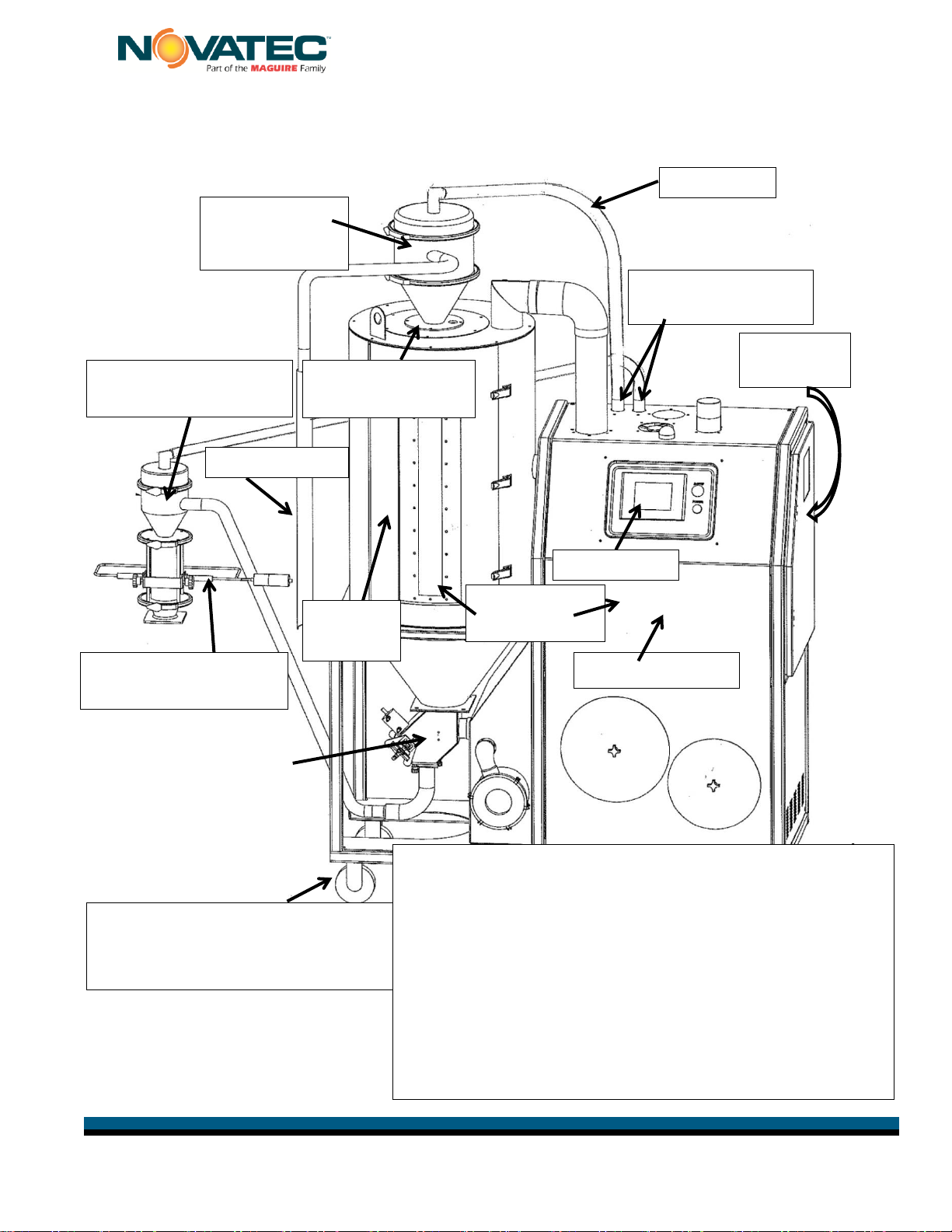
Basic Components of NOVATEC NWDC Dryer Assembly
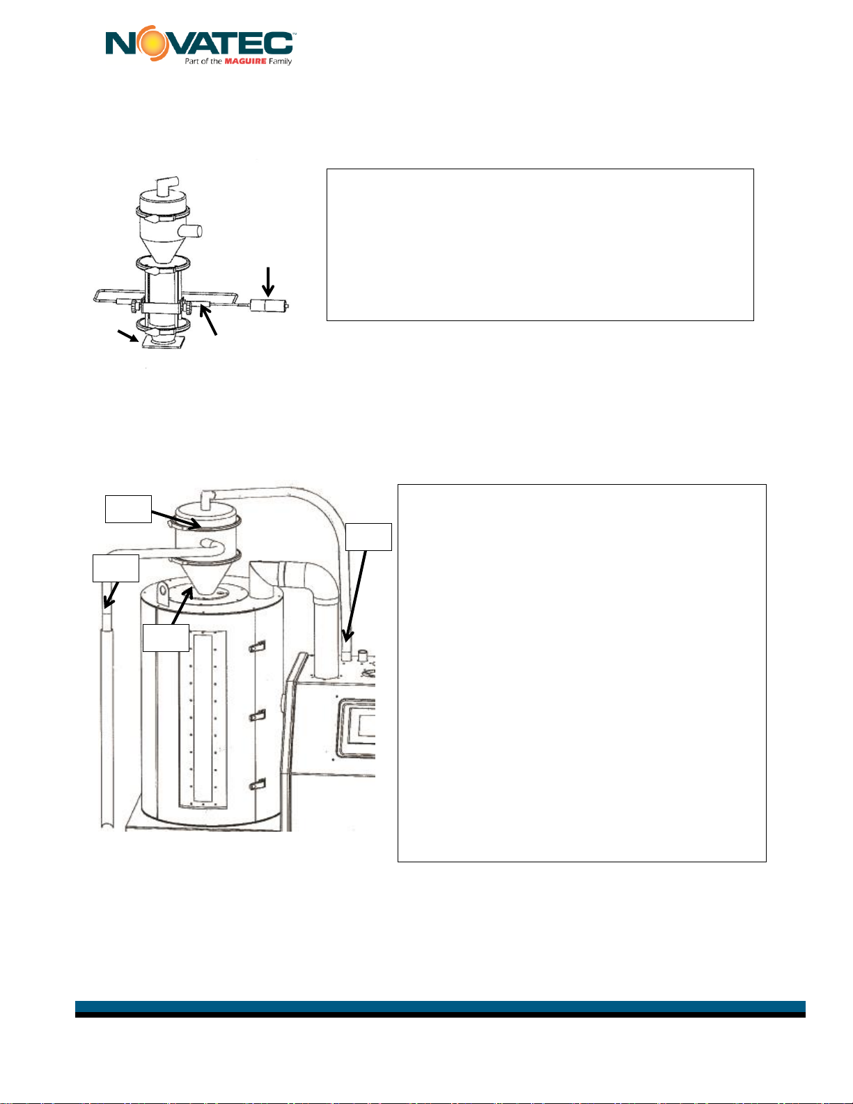
1.2.1 Prepare/Assemble Machine Mount Receiver
NOTE: As you proceed with assembly, make sure that all bolts and hose
clamps are securely fastened to ensure that there are no air or material
leaks in the system. Do not use excessive flex hose but avoid sharp turns
as this will hurt the efficiency of the system operation.
1-B
1-C
1-A: If Machine Mount Receiver base has not been pre-drilled,
remove base from Machine Mount Receiver and drill holes
to match machine throat hole pattern and re-attach base to
MM Receiver.
1-B: Attach Photo Eye Level Sensor to the bracket provided.
1-C: Connect 115/1/50-60 VAC wiring to twist lock plug.
(supplied)
1-A
Vacuum
Purge Valve
Identifying Major Components:
Vacuum
Purge Valve
Vacuum
Purge Valve
Receiver
Mounting Plate
Hopper
Receiver
VR-5 or VR-12
NWDC Dryer
Photo Eye Level
Sensor
Machine Mount
Receiver
Electrical
Enclosure
EPV Dual Station
Vacuum Valve
Stubs
Pickup Wand
Material
Hopper
Control
Panel
Dryer/Hopper
Assembly
Flex Hose
5” Casters
Pre-mounted on all EXCEPT-150
Install first on -150
Tools You Will Need for Assembly:
Hacksaw to cut PVC flex hose
Flat Blade Screwdriver and/or 5/16” socket for hose
clamps
5/32” Allen wrench to mount Receivers
Drill press and drill bit sized to match mounting holes
on machine throat so holes can be drilled in base of
Machine Mount Receiver. (Unless base is pre-drilled)
6’-8’ Ladder
Tape measure
NWDC IM 26 MAR 2014 © 2014 Novatec, Inc. All Rights Reserved Page 8 [Type text] [Type text]
NWDC IM 26 MAR 2014
2.1 Prepare/Assemble Machine Mount Receiver
NOTE: As you proceed with assembly, make sure that all bolts and hose clamps are securely fastened to
ensure that there are no air or material leaks in the system. Do not use excessive flex hose but avoid
sharp turns as this will hurt the efficiency of the system operation.
2.2 Mount Hopper Receiver & Connect Flex Hose and Pickup Wand
Hopper Receivers with Blowback are supplied with a male/female twist lock plug to which 115/1/50-60 VAC
should be wired. A clean source of 80-120 psi compressed air should be connected to the supplied FNPT fitting.
(3/8” on the VR-5 and ¼” on the VR-12)
Roll the NWDC into position next to the process machine it will be serving.
1-A
2-A: Remove cover plate from top of Material Hopper
(save bolts and washers) then, after removing
green tape from flapper, place Hopper Receiver
in hole. Align inlet stub to face direction from
where material will be pulled. Fasten the Receiver
to the Hopper using the saved ¼” x 20 bolts and
washers.
2-B: Place hose clamp over one end of flex hose and
push end of the hose on to the material inlet stub
on the side of the receiver. Fasten hose clamp
securely.
2-C: Cut the flex hose to a length that will allow the
5’ long pickup wand to reach all corners of the
bulk container supplying the material to the
dryer hopper. Push the cut end of the flex hose
over the end of the pickup wand and secure with
hose clamp.
2-D: Follow same instructions to attach flex hose
running from the vacuum stub on top of the
Hopper Receiver to the nearest EPV Dual
Station Vacuum Valve Stub extending from
the top of the dryer. (See illustration)
2-A
2-B
2-D
2-C
2-A
1-B
1-C
1-A: If Machine Mount Receiver base has not been pre-drilled,
remove base from Machine Mount Receiver and drill holes
to match machine throat hole pattern and re-attach base to
MM Receiver.
1-B: Attach Photo Eye Level Sensor to the bracket provided.
1-C: Connect 115/1/50-60 VAC wiring to twist lock plug.
(supplied)
1-A

NWDC IM 26 MAR 2014 © 2014 Novatec, Inc. All Rights Reserved Page 9 [Type text] [Type text]
NWDC IM 26 MAR 2014
NOTE: LOCATION
Position your NWDC Series dryer in a location where material and vacuum hoses will not be
disturbed. Allow sufficient distance (at least 2 feet) from the surrounding equipment, so the
access doors may be opened to perform routine maintenance on the dryer and for safe
operation.
2.3 Install Machine Mount Receiver and Connect Flex Hose
3-A: Bolt the Machine Mount Receiver to the process machine throat with user-supplied bolts.
3-B: Push one end of the flex hose all the way onto the material inlet stub on the side of the receiver and
fasten it securely with a hose clamp (supplied).
3-C: String flex hose to the vacuum purge valve tube (attached to the bottom of the hopper) cut it to
length and fasten securely with a hose clamp.
3-D: Attach one end of flex hose to the vacuum inlet stub on top of the Machine Mount receiver and
fasten it securely with a hose clamp. String the flex hose to the farthest EPV Dual Station
Vacuum Valve Stub extending from the top of the dryer. Cut flex hose to length and attach it
securely to the stub with a hose clamp.
3-A
3-B
3-C
3-D
4-A
Entry point for power
NWDC IM 26 MAR 2014 © 2014 Novatec, Inc. All Rights Reserved Page 10 [Type text] [Type text]
NWDC IM 26 MAR 2014
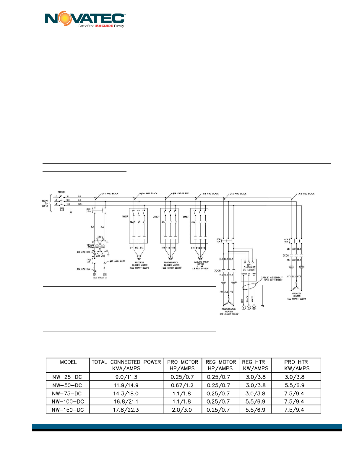
2.4 Electrical Connections
The NW-DC Series dryers come from the factory with all control circuits wired and the
dryer needs to be connected to the proper power source. A quick-connect plug should
be installed if moving the NWDC to other process machines is anticipated.
CAUTION
All electrical connections must be made by qualified electricians, per national
and local electrical codes.
Disconnect and lock out the main power source before making the electrical connection.
4-A: (See illustration above)
Turn the Main Disconnect on the electrical panel door to the “OFF” position, lock
out the main power source and open the electrical enclosure. Per the electrical
diagram, install the main power wire to the main disconnect switch holder and
install the ground wire.
Full size electrical drawings are included with this Instruction package for the voltage
of the dryer you ordered.
460V/3Ph/60Hz
NOTE: Please make sure all electrical connections are tight. It is not common
but a loose connection is possible after a long truck ride.
NOTE: 3 Phase detection is included on this
model. If the connection is not correct, a pop-up
alarm will appear on the touch screen upon
startup. You should immediately correct this
condition.

NWDC IM 26 MAR 2014 © 2014 Novatec, Inc. All Rights Reserved Page 11 [Type text] [Type text]
NWDC IM 26 MAR 2014
2.5 Pre-Cooler Water Connections
A Cooling Coil is installed in NWDC series dryers and is required to lower the hopper
return temperature and this increases the efficiency of dryer IF THE DRYING
TEMPERATURE IS ABOVE 225°F .
5-A: Tower, city or chilled water is required at between 40 to 85°F. Connect the cooling water
supply and return using flexible hose that is at least 2 feet long, to allow for easy removal of
the cooling coil for cleaning. The water flow rates and the required customer connection sizes
for different models are shown in the chart below.
NOTE: Cooling water is required if drying temperature is over 225°F.
The process airstream must be connected to an external cooling coil if the drying
temperature is below 170°F. Contact Factory for Options.
2.6 Compressed Air Connection
The touch screen control operates a dual station vacuum valve inside the dryer to
activate vacuum to either the hopper receiver or the machine mount receiver. A clean
compressed air supply (60-90 psi) should be connected to the 1/8” NPT inlet.
Model
NW-25NC-DC
NW-50NC-DC
NW-75NC-DC
NW-100NC-DC
NW-150NC-DC
Water Inlet/Outlet
Connections
3/8”
3/8”
3/8 “
3/8”
3/8”
Flow Rate-GPH
Gallons per Hour
0.25
0.5
0.75
1.0
1.5
5-A
3/8” Water Outlet Connection
On NWDC-25 through NWDC-75
3/8” Water Inlet Connection
On NWDC-25 through NWDC-75
3/8” FNPT Water connections for
-100 and -150 models
Knockout for electrical
connection
Compressed Air
Connection for Receiver
Selection Valve
NOTE: ½” O.D. water hose
should be used to get
proper water flow.

NWDC IM 26 MAR 2014 © 2014 Novatec, Inc. All Rights Reserved Page 12 [Type text] [Type text]
NWDC IM 26 MAR 2014
2.7 Hopper Extensions
If you ordered a hopper extension, it will be a bolt-on type. The extension will be
installed at the factory if the overall height of the unit fits into a standard height truck
for shipping. If the unit is too tall for the extension to be factory-mounted, it will be
shipped in a separate container and must be installed at the processor’s plant.
2.8 Adjustable Diffuser Cone Positioning
IMPORTANT FOR PROPER DRYING
We have found that processors can improve the
efficiency of their drying process by adjusting the
position of the diffuser cone as described below.
You are now ready to start the dryer.
See QuickCard attached to dryer.
Use bolts supplied to
mount the extension to
the top of the hopper.
Bolt top of hopper to the
extension –lift into place
- then bolt the extension
to the top of the hopper.
The diffuser cone should be placed in
the lower position (shown) when drying
virgin resin or resin with a low
percentage of regrind.
When drying resin with a high % of
regrind, spread the clip, raise the cone
and place the clip through the lower set
of holes.
Clip through upper
set of holes for low
% of regrind.
Clip through lower
set of holes for high
% of regrind to raise
level of cone.

NWDC IM 26 MAR 2014 © 2014 Novatec, Inc. All Rights Reserved Page 13 [Type text] [Type text]
NWDC IM 26 MAR 2014
3 SALES AND SERVICE
NOVATEC maintains qualified sales, engineering, and service personnel to assist in any
way possible. If you have any comments concerning the types of equipment which
NOVATEC manufactures that might improve your process, or any questions concerning
service, we urge you to contact us. Please have you Model and Serial Number handy.
4 SHIPPING AND INSPECTION
Although NOVATEC uses reputed carriers to deliver products, it has no control over the
products once it leaves the manufacturing facility. Upon receiving the products, thoroughly
inspect all equipment inside and out for damage that may have occurred during shipment.
If any damage is found, a claim should be filed immediately with your carrier.
NOVATEC thoroughly tests and inspects all products before shipment. You are to make
the piping, and electrical connections for final installation and commissioning. If there any
problems, shut down the equipment and contact the NOVATEC Technical Service
Department.
5 PRINCIPLE OF OPERATION
The NWDC Series is designed to convey moisture laden resin from a source container,
dry it, and deliver it to the throat of a process machine.
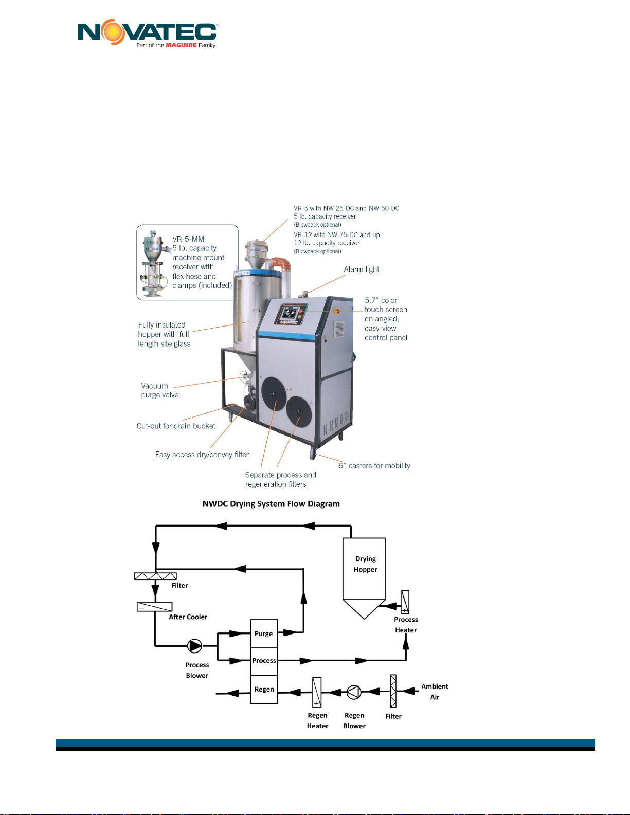
5.1 Resin Drying
The NWDC NovaWheel Series dryer was engineered and designed to effectively remove
moisture (in the vapor state) from hygroscopic plastic resins. This process is accomplished
by the continuously rotating desiccant wheel and the three air streams (Process, Purge and
Regeneration). The Process return air is exposed to an adsorbing media (desiccant wheel)
in a sealed air stream, where the desiccant adsorbs the moisture from process air. After the
desiccant has adsorbed the moisture, it is exposed to a Regeneration air stream which has
been pre-heated to a temperature of about 380°F. (190°C). This causes the moisture to be
driven out from the desiccant and prepares it for more moisture adsorption. Now the
desiccant media passes through third air stream called purge air stream. Here the
desiccant media is cooled down by some of the process air before entering back into the
process to provide for better performance. The three air streams (process, regeneration
and purge) are separated by special Teflon fabric coated silicon seals. The process air and
regeneration air is compressed by using regenerative blowers.
The dry air from the dryer is then heated to the desired drying temperature by an electric
heater located in the NWDC cabinet. The hot dry air enters the hopper at the bottom and
removes moisture vapor from the resin in the hopper. The air from the top of the hopper is
returned to the dryer, where it is filtered, passed through the desiccant wheel to remove
moisture from the air stream and cooled before the process blower sends the air back
through the heater and into the bottom of the hopper again in a continuous process.
NWDC IM 26 MAR 2014 © 2014 Novatec, Inc. All Rights Reserved Page 14 [Type text] [Type text]
NWDC IM 26 MAR 2014
5.2 Resin Conveying
A regenerative blower pulls resin from a bulk container through a pickup wand and flexible
hose to an appropriately-sized vacuum receiver where the material is fed into the drying
hopper, as needed. As the material passes through the drying hopper it is metered through
a vacuum takeoff valve to a machine mount vacuum receiver mounted on the process
machine, thereby maintaining a constant flow of dry material to the feed throat.
5.3 Product Familiarization
The major components and their locations are shown below plus a System Flow Diagram.
NW-100-DC

NWDC IM 26 MAR 2014 © 2014 Novatec, Inc. All Rights Reserved Page 15 [Type text] [Type text]
NWDC IM 26 MAR 2014
5.4 SPECIFICATIONS –NWDC Dry Convey Series
Process Air dew Point (nominal): -40ºF (-40°C)
Drying Temperature: 150-350°F (66-177°C)
Air and Material Hose Diameter: 1.5” ID (40 mm)
Compressed Air Fittings for Hopper Receivers with Blowback:
VR-5-B: 3/8” FNPT, VR-12-B: ¼” FNPT
Compressed Air requirements for Blowback: 80-120 psi (5.5-8.3 Bar)
*Based on material bulk density of 38 lb./ft3
Model
NW-25NC-DC
NW-50NC-DC
NW-75NC-DC
NW-100NC-DC
NW-150NC-DC
*Max Material Flow –
Lbs./Hr (kg/hr)
25
(11.4 kg/hr.)
50
(22.7 kg/hr.)
75
(34.0 kg/hr.)
100
(45.4 kg/hr.)
150
(68.2 kg/hr.)
Voltage –Phase - Hz
460-3-60
Hopper Receiver
VR-5
VR-5
VR-12
VR-12
VR-12
Machine Mount
Receiver
VR-5MM
VR-5MM
VR-5MM
VR-5MM
VR-5MM
Wheel Speed -
Nominal RPH
(revolutions per hr.):
10
10
10
10
10
Water Inlet/Outlet
Connections
3/8”
3/8”
3/8”
3/8”
3/8”
Flow Rate-GPH
Gallons per Hour
0.25
0.5
0.75
1.0
1.5

NWDC IM 26 MAR 2014 © 2014 Novatec, Inc. All Rights Reserved Page 16 [Type text] [Type text]
NWDC IM 26 MAR 2014
6 FUNCTION CONTROLS
The NWDC Series dryers come complete with the following controls:
6.1 Process Temperature Control (Drying Temperature)
The Temperature Control is a part of the NovaWheel NovaTouch PLC controller and
controls the process outlet temperature as per the set value. In addition, there is a
process high temperature limit thermostat that is provided for extra safety. (Refer to the
controller section).
6.2 Regeneration Temperature Control
The regeneration temperature is controlled by the NovaTouch PLC controller. In addition,
there is a regeneration high temperature limit thermostat, which provides extra safety. The
regeneration temperature is set at about 380°F. (190°C) and should not be changed.
6.3 Process & Regeneration Air Filter Pressure Switches (PS)
The air pressure differential across the process
filter and the regeneration filter is monitored
and the NovaTouch display will alarm and show
when a filter needs to be cleaned or replaced.
These are factory set but often need to be
adjusted in the field once the customer loads
resin in the hopper.
Access pressure switches through after removing the back panel from the dryer. Remove
Phillips screw that holds clear cover in place (Fig. 1) . Turn knob clockwise or counter-
clockwise to either increase or decrease
6.4 Process Air Dew Point Monitor
It measures the process air dew point from the dryer.
6.5 Intelligent Regeneration
Intelligent Regen constantly monitors the regeneration inlet and outlet temperatures and
controls them to optimize the energy and dew point performance of the dryer.
6.6 Conveying Control
Provides entry of load/dump times and number of attempted loads before No-Load Alarm
is activated plus Blow Back control, if specified.
Process Filter Pressure Switch
Regen Filter Pressure Switch
Fig. 1
Fig. 2
NWDC IM 26 MAR 2014 © 2014 Novatec, Inc. All Rights Reserved Page 17 [Type text] [Type text]
NWDC IM 26 MAR 2014
7 PRE-OPERATING SYSTEM CHECK
Once material, vacuum hose, water and electrical connections are made, the NWDC Series
dryer should be given a final checkout.
7.1 Starting The Dryer
Turn the main disconnect switch to “ON” position to power the dryer.
To start the dryer depress the “ON/OFF” button on the controller.
The blowers and heaters are now energized and the desiccant wheel will begin turning
and start to dry the return air. It will take several minutes and a couple revolutions
of the wheel, for the dew point to get down to the -40° dew point.
WARNING: E-STOP should only be used in True Emergency conditions.
Repeated use of emergency stop can cause dryer component failure.
Always use to turn dryer “ON or “OFF”.
7.2 Checking Electrical Phase
Your NOVATEC NWDC Dryer includes Phase Detection. This is particularly
important for dryers that may be moved around the plant. When you turn the MAIN
Disconnect switch to the ON position, a Pop-Up Alarm will appear on the screen if
the connection is not correct. You should immediately correct this condition.
WARNING:
Any wiring procedure should only be done by a qualified electrician familiar with three
phase electrical wiring.
7.3 Changing From F° to C°
Degrees can be set to C or F on the NOVATEC SCREEN…
Basic Machine Configuration.
(See page 28)
NOTE: All dryers are set to display temperatures in degrees F
when shipped. If you change the control to display degrees C,
you must also change the DIP switch located on Siemens
module 231-7PD22-OXAO located behind the electrical panel
access door.
DIP switch to change from
Fahrenheit to Centigrade

NWDC IM 26 MAR 2014 © 2014 Novatec, Inc. All Rights Reserved Page 18 [Type text] [Type text]
NWDC IM 26 MAR 2014
8 NovaTouch™CONTROL
8.1 System Conventions:
All information and data displays will appear two dimensional in configuration and flat. All data entry
points or operational features will appear three dimensional in configuration and raised or depressed in
appearance depending on their operational position.
Proceed as follows:
1. Touch the relevant IO field on the screen.
The numerical screen keyboard opens and displays the current value.
2. Set the value.
You can only operate keys which are visualized in 3D format. The type of value to be
entered determines whether a key is enabled or disabled.
The following options for entering values are available:
The current value is deleted when you enter the first character. Enter the value again.
Use the and keys to move the cursor within the current value. You can now
edit the characters of the current value or add characters.
Use the key to delete the character to the left of the cursor.
Use the key to change the sign of the value.
Select to view the info text of the IO field.
Select to confirm your entries or cancel them with . Both actions close the
screen keyboard.
Numerical Entries: When you touch an IO
field on the HMI device touch screen that
requires only a numerical entry (Password,
Temperature, number of seconds etc.) the
following keyboard will appear.
Alpha/Numeric Entries:
When you are prompted to enter alphabetical
and numerical data (Resin Names/Numbers)
this screen will appear:
NWDC IM 26 MAR 2014 © 2014 Novatec, Inc. All Rights Reserved Page 19 [Type text] [Type text]
NWDC IM 26 MAR 2014
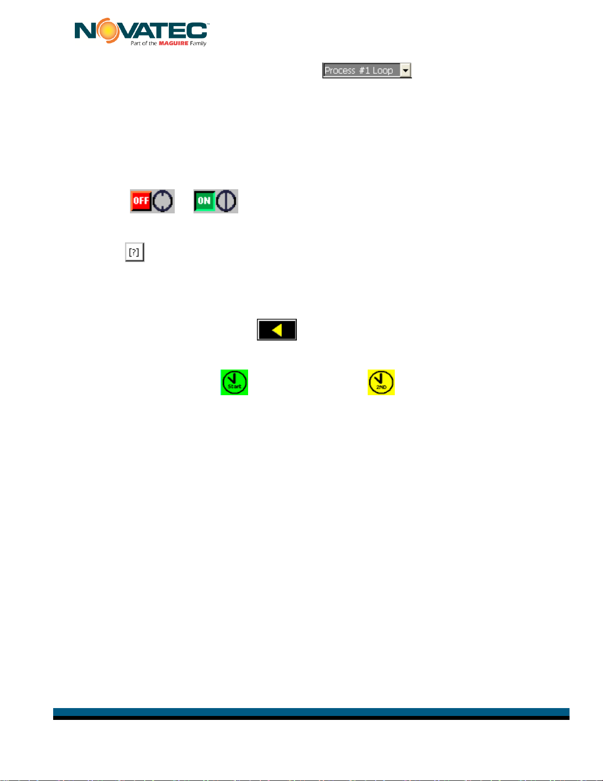
Multiple choice inputs will use the DOWN arrow to alert you to a drop down
menu. Pressing the associated display window will cause the drop down menu to appear.
The keyboard is automatically hidden again when input is complete.
The condition of a switch or display will be displayed in both language and the international
ON/OFF icon.
Example:
“[?]” or an may appear on any screen, or in any alarm message. This is the indication that
there is additional information available. By pressing the symbol, an information page will
appear on the screen. The information page will be removed by pressing the X in the upper
right hand corner of the page.
Each time you exit a screen via the touch pad, the PLC EEPROM is programmed with
the new information. The exception to this function is the Real Time Clock.
Other symbols will include: Automatic start is on. Automation 2nd set point is on.
Language on screen is U.S. English as indicated on Main menu by en-US.
NWDC IM 26 MAR 2014 © 2014 Novatec, Inc. All Rights Reserved Page 20 [Type text] [Type text]
NWDC IM 26 MAR 2014
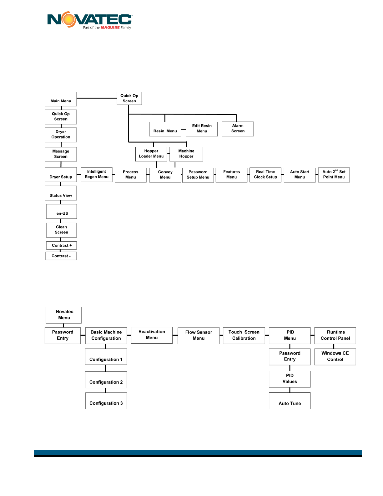
8.2 Screen Maps:
For all operational functions available to processor:
The NOVATEC screen map defines all of the screens provided for all engineering functions:
(Available with NOVATEC level password only)
NOVATEC
MENU
This manual suits for next models
5
Table of contents
Other NovaTec Dryer manuals


Popular Dryer manuals by other brands


 owner's manual")


Electrolux Professional
Electrolux Professional TE1220E user manual

Electrolux Professional
Electrolux Professional Compass Pro TD6-24S installation manual

Kenmore
Kenmore 8751 - 6.7 cu. Ft. HE2 Electric Dryer Use and care guide

Whirlpool
Whirlpool LE4900XK Use & care guide

Whirlpool
Whirlpool WGD8000DW installation instructions

Cylinda
Cylinda T7200VPK user manual