NovaTec NovaDrier ND-7 User manual

U.S. Patent No.
US
6,584,701 B1
Document: ND IM 3 JAN 2017
NovaDrier
™MEMBRANE DRYER
for Plastics
MODELS: ND-7, ND-25, ND-50, ND-75,
ND-100, ND-150, ND-200
©NOVATEC, Inc. 2017 All Rights Reserved
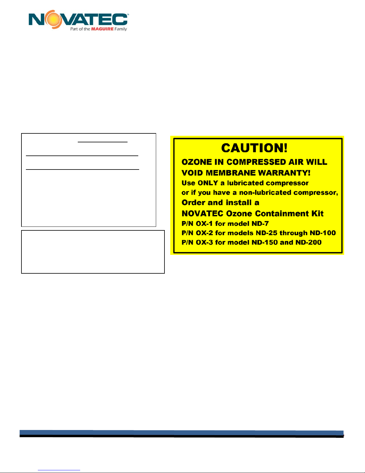
NOTE:
See important
information
about air supply
on next page.

Instruction Manual ND IM 3 JAN 2017
Instruction Manual IM ND 3 JAN 2017 Page 2
NOTES:
Please record the following information,
which is specific to this piece of
equipment, in the space provided. Our
Parts/Service Department will need these
numbers to properly respond to any of
your requests.
Instruction Manual: ND IM 3 JAN 2017
Model #:___________________________
Serial #____________________________
DISCLAIMER: NOVATEC, Inc. shall not be liable for
errors contained in this Instruction Manual nor for
misinterpretation of information contained herein.
NOVATEC shall not, in any event, be held liable for any
special, indirect or consequential damages in
connection with performance or use of this information.

Instruction Manual ND IM 3 JAN 2017
Instruction Manual IM ND 3 JAN 2017 Page 3
Table of Contents
1-UNPACKING AND INSPECTION .....................................................................................................4
1.1 Unpacking...................................................................................................................................4
1.2 General Inspection & Mounting................................................................................................5
1.3 Clamp Ring Inspection..............................................................................................................6
2 SPECIFICATIONS.............................................................................................................................7
2.1 NovaDrier STANDARD COMPONENT Set Points....................................................................7
3 INSTALLATION.................................................................................................................................8
3.1 Mounting The Dryer...................................................................................................................8
3.2 Connecting Power......................................................................................................................8
3.3 Compressed Air .........................................................................................................................9
3.3.1 Compressed Air Requirements ..........................................................................................9
3.3.2 Connecting Compressed Air.............................................................................................10
3.3.3 Condensate Drains ............................................................................................................10
4 DESCRIPTION OF OPERATION ....................................................................................................11
5 INITIAL START-UP & OPERATION ...............................................................................................12
5.1 Turning The Dryer On..............................................................................................................12
5.4 Other Parameters.....................................................................................................................14
6 USING THE 7 DAY TIMER OPTION:..............................................................................................15
7 SETTING ENERGY SAVER OPTION ON ND-100 AND LARGER SIZES......................................16
8 UPDATING FIRMWARE..................................................................................................................17
9 TROUBLESHOOTING GUIDE........................................................................................................18
9.1 Dryer Fault Lights ....................................................................................................................18
9.2 Power Failure ...........................................................................................................................18
9.3 Troubleshooting Chart ............................................................................................................19
10 MAINTENANCE AND INSPECTION SCHEDULE ........................................................................20
10.1 Vendor Instructions...............................................................................................................22
10.1.1Compressed Air Inlet Filters ............................................................................................22
10.1.2 Round Re-Circulation Air Filter.......................................................................................23
10.1.3 Heater Housing Thermostat............................................................................................23
10.1.4 Spare Parts Notes............................................................................................................23
11 WARRANTY – NOVATEC, INC. - Effective Date 21 SEPT 2016 ................................................24

Instruction Manual ND IM 3 JAN 2017
Instruction Manual IM ND 3 JAN 2017 Page 4
1- UNPACKING AND INSPECTION
Congratulations, you have purchased the finest Dryer on the market from the finest dryer
manufacturer. It has a (2) year warranty (as long as you replace the filter elements regularly and
exercise good maintenance – see the warranty information in section 8). This manual will provide
you with proper procedures to insure that you will be completely satisfied with your purchase.
Please review this manual carefully.
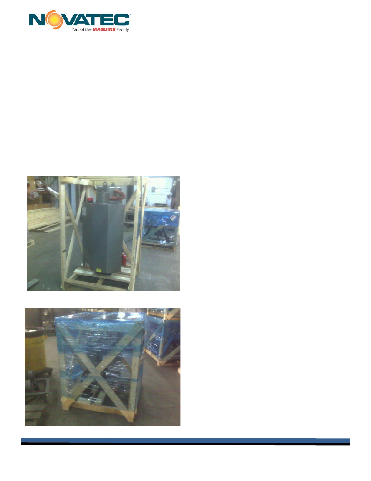
1.1 Unpacking
Caution should be exercised to make sure the equipment is not damaged during handling. The
crate must be removed carefully. The machine must not be used to pry against when removing
the crate. The dryer is usually shipped completely assembled and requires no further assembly
prior to installation.
Remove crating carefully.
Do not pry against the dryer
or hopper.
Dryer is typically shipped fully
assembled, ready to be
installed.

Instruction Manual ND IM 3 JAN 2017
Instruction Manual IM ND 3 JAN 2017 Page 5
1.2 General Inspection & Mounting
When the unit is unpacked, make a visual inspection looking for missing parts or damage, which
may have occurred during shipment. Some parts, such as hoses, and hose clamps may be
packed inside the hopper as well as the instruction manual. It is important that all electrical and
piping connections should be checked for tightness because vibration during transit may cause
them to loosen.
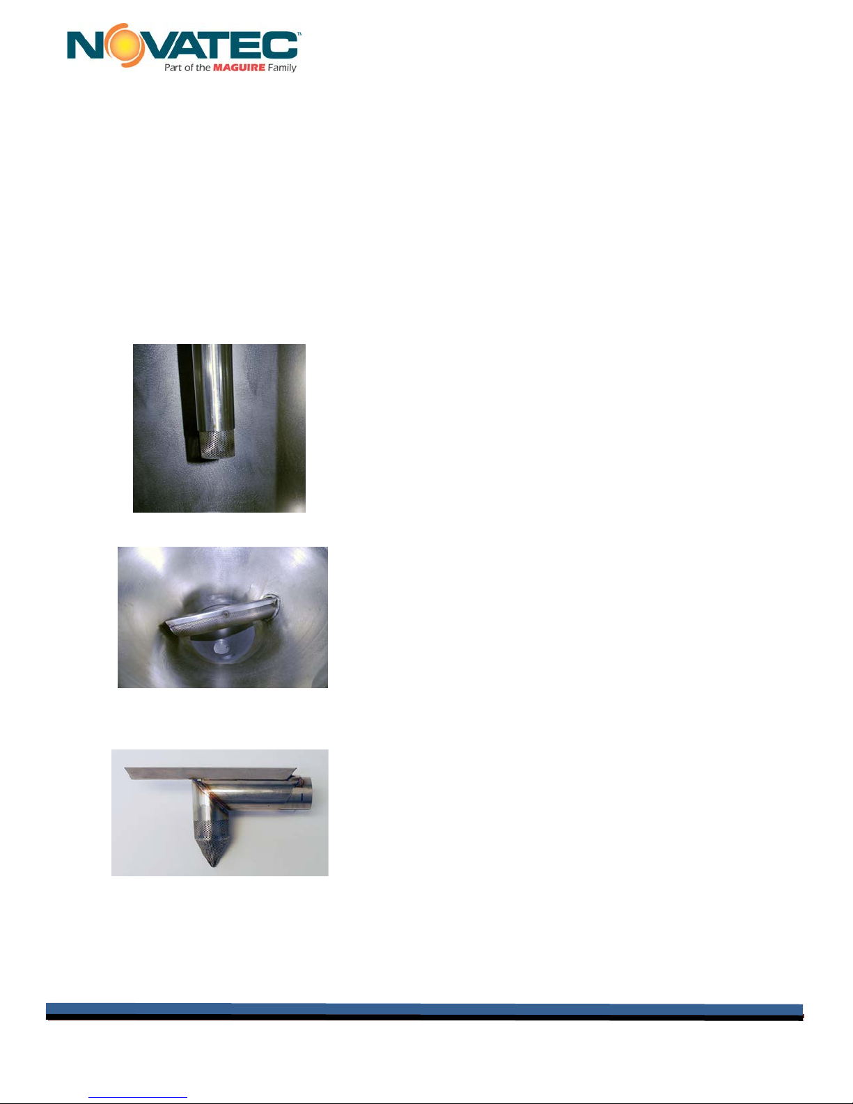
Inside of the hopper door, the (2) perforated air diffuser tubes (upper & lower) should be
thoroughly cleaned to remove any dust, moisture or oil that may have accumulated during
shipment. The diffuser tubes must be reinstalled so they are properly aligned and secure. The
upper diffuser tube must be installed at the end of the vertical tube in the center of the hopper (it is
a friction fit) and should stick out from the end of this tube as follows:
NovaDrier Upper
Diffuser Tube
NovaDrier Lower
Diffuser Tube
Optional Short Run Diffuser Tube for use
when hopper is less than 100% full.
NOTE: NovaDriers should always be
run with a 100% full hopper- never
below 75% full.

Instruction Manual ND IM 3 JAN 2017
Instruction Manual IM ND 3 JAN 2017 Page 6
1.3 Clamp Ring Inspection
Make sure the clamp rings on the hopper that connect the sections of the hopper
together are tight, particularly the one at the lower part of the hopper that connects the
bottom of the conical section. Note that the clamp ring that attaches the hopper lid
does not have to be as tight.
If loose,
tighten
clamp rings
NOTE: If your hopper is
fitted with an extension,
those clamp rings
should also be checked
for tightness.

Instruction Manual ND IM 3 JAN 2017
Instruction Manual IM ND 3 JAN 2017 Page 7
ALL MODELS
2 SPECIFICATIONS
**Note: If set point is exceeded by 5°F (3°C) the heater will shut down for 1
minute to allow it to come back to set point. If it does not, the dryer will alarm
and shut down.
2.1 NovaDrier STANDARD COMPONENT Set Points
Air Amplifier setting:
See sticker inside control box
LOWER air pressure regulator setting (R1) - located inside the
upper part of the control box:
See sticker inside control box
UPPER air pressure regulator setting (R2) - located inside the
lower part of the control box:
See sticker inside control box
Low air pressure switch:
70 PSIG (4.7 BagG)
Over-temperature shut-down set point from both the
temperature controllers (see **note above):
5°F (3°C) higher than the control set
point after one minute
Angle needle valve that controls flow to Hygro Dew Point Sensor
option (if supplied):
(2) turns open from full closed
Heater Thermostats - legend “TSH” (if supplied):
375°F (191°F)
Required Compressed
Air Pressure - PSIG
85-125 psig (5.9 -8.7 Barg)
Max. Temperature
°F/ºC
100°F / 38°C
Max Inlet Dew Point
°F/ºC
100°F / 38°C
Process Air Outlet
Temp. °F/ºC (max)
350ºF / 163°C
Process Air Dew Point
(max)
-40ºF / -40ºC

Instruction Manual ND IM 3 JAN 2017
Instruction Manual IM ND 3 JAN 2017 Page 8
3 INSTALLATION
3.1 Mounting The Dryer
Mount the NovaDrier to the processing machine (if machine mounted). Use the control
panel support bracket supplied on the bottom of the control box, as the control box must be
supported properly.
CAUTION: FOLLOW ALL NATIONAL AND LOCAL ELECTRICAL AND MECHANICAL CODES,
AS REQUIRED. ONLY QUALIFIED AND TRAINED PERSONEL SHOULD INSTALL AND
OPERATE THIS EQUIPMENT
3.2 Connecting Power
Refer to the specifications in Section 2 and the mechanical and electrical drawings
provided.
Connect the required electrical power to the unit through a main line
disconnect (field supplied) as indicated on the NOVATEC nameplate,
which is located on the side of the control box. Because the
controllers and various sensors are sensitive to “Industrial Noise” the
system must be properly connected to true earth ground. This is the
only power connection necessary as the system is completely pre-
wired.
Main power connection inside
control panel
NovaDrier machine
mounting.
Control panel support
bracket.
(Must be installed)

Instruction Manual ND IM 3 JAN 2017
Instruction Manual IM ND 3 JAN 2017 Page 9
3.3 Compressed Air
3.3.1 Compressed Air Requirements
IMPORTANT NOTE: The introduction of OZONE to the flow of compressed air
will damage the membrane and void the warranty.
OZONE in the atmosphere near the air compressor intake can also damage the
NovaDrier membrane.
To avoid membrane damage from atmospheric ozone please order and install the
Catalyst Modules listed above.

Instruction Manual ND IM 3 JAN 2017
Instruction Manual IM ND 3 JAN 2017 Page 10
3.3.2 Connecting Compressed Air
Connect a clean, ozone-free, vapor-free and liquid water-free compressed air line to the
compressed air inlet ball valve located on the left side of the control panel.
See the minimum compressed air inlet line size requirement below. The
pressure of the compressed air to the system should be at least 85 psig but
not more than 125 psi (note that the system will run more efficiently at higher
air pressures). The inlet compressed air temperature should be less that 100°F. Note
that the (2) coalescing inlet compressed air filters on the NovaDrier each have an
internal condensate trap that is designed to remove small amounts of water droplets
from un-dried incoming compressed air but they are not designed to remove liquid
water. Make sure that hazardous vapors, like solvents or ozone, are not being
introduced into the compressed air system that is feeding the NovaDrier.
3.3.3 Condensate Drains
Connect the automatic compressed air condensate drains at the bottom of the
(2) compressed air filters on the side of the cabinet, so the condensate is
captured and disposed of properly. If the drains are not piped away, oily water
may spray down periodically from the automatic drains. Use a 1/8” npt male
fitting to connect into each drain.
MODEL
ND-7
ND-25
ND-50
ND-75
ND-100
ND-150
ND-200
Minimum
compressed air
line size
3/8” hose
or 10 mm
3/8” hose or
10 mm
3/8” hose or
10mm
3/8” hose or
10mm
1/2" hose
or 12 mm
3/4" hose
or 20 mm
3/4” hose
or 20mm
Connect air
LOWER of 85-
125 psig here.
Condensate drains:
Collect discharge or
attach drain lines.
See chart below
for proper line
compressed air
line size for your
dryer model, or
the sticker on
dryer cabinet.
DO NOT USE
REDUCERS
THAT WILL
RESTRICT AIR
IMPORTANT

Instruction Manual ND IM 3 JAN 2017
Instruction Manual IM ND 3 JAN 2017 Page 11
4 DESCRIPTION OF OPERATION
•Compressed air is filtered by two coalescing filters in series, to remove all aerosols as
well as any particles, all down to 0.01 micron.
•Inside the control box the compressed air flow splits. The bulk of the airstream is
expanded to atmospheric pressure through a pressure regulator (to lower the dew point),
heated and injected into the middle of the hopper. An Air Amplifier, driven by the
expansion of the compressed air, is used to re-circulate much of the air in the upper part
of the hopper.
•This insures that heat is transferred into the material quickly, evenly and at the correct
velocity, to insure good drying. The inlet air temperature to the hopper is controlled by a
thermocouple and a solid state temperature controller (located in the right side of the
control box and it is the top controller & labeled “UPPER HEAT”).
•The rest of the compressed air goes through a special membrane, located inside the
control box. This membrane filters out the water vapor, which is continuously exhausted
through vents in the side.
•The dry air is then expanded to atmospheric pressure through a pressure regulator,
heated and injected into the bottom of the hopper to dry the material in the lower part of
the hopper. The dry air temperature to the lower part of the hopper is controlled by a
thermocouple and a solid state temperature controller (located in the right side of the
control box and it is the one on the bottom labeled “LOWER”). After drying the material,
the moisture laden air is vented through the relief valve at the top of the hopper.
5
Air Flow Diagram of the
patented NovaDrier™
Patent # 6,584,701 B1

Instruction Manual ND IM 3 JAN 2017
Instruction Manual IM ND 3 JAN 2017 Page 12
5 INITIAL START-UP & OPERATION
WARNING:
1) Never turn off the compressed air flow to the system while power is on, as compressed
air must always be flowing for proper operation of the heaters and to avoid product and
system damage from overheating and poor temperature control.
2) The (2) insulated heaters and the piping from the heaters inside the control box are hot.
When operating the system with the door of the control box off, be careful to avoid
touching these hot surfaces.
3) If the NovaDrier is mounted on a floor stand with casters, be careful moving it, to avoid
tipping, as damage and injury may result. Material loaders and other equipment located
on top of the drying hopper will increase the need for care when moving this equipment.
4) The drying hopper and the red silicone hoses may be hot.
5) Only qualified and properly trained personal should operate this equipment!
Refer to the drawing and the information in this Technical Manual. Contact NOV ATEC if
there are any questions about how to operate or maintain this equipment!
Before starting, the compressed air inlet valve (located on the side of the dryer) must be fully open.
Fill the hopper with material, being careful not to overfill it. The hopper should never be less full than
the Minimum Level arrow next to the sight glass. When ready to start the system, fully open the
compressed air inlet valve (located on the side of the dryer cabinet) and assure that a minimum of 85
psi shows on the dryer’s air pressure gauge. Compressed air should be flowing through the system.
Turn on control and immediately set both temperature controls to the proper drying temperature (see
“Changing the Drying Temperature”, below).
5.1 Turning The Dryer On
After making sure that compressed air is flowing to the dryer
(pressure gauge should show 85-125 psi), and making sure
that the drying hopper is filled to above the minimum level
shown next to the sight glass, turn the dryer “ON” using this switch.
Control will display the factory default of 160F°.
Valve in
CLOSED
(horizontal)
position.
Valve in
OPEN
(vertical)
position.
Air
To Dryer
Air

Instruction Manual ND IM 3 JAN 2017
Instruction Manual IM ND 3 JAN 2017 Page 13
5.2 Choosing F° or C°
On the display under UPPER HEAT –
(NOTE: initial temps shown are the set points entered during testing.)
unt
Selecting F° or C° for Dew Point
1- Find the board behind the dew point display.
2- Press & HOLD one of the two white buttons.
3- The display will change to the new selection.
4- Release the button and the dew point readout
will be in the new selection.
1- Press the upper left and lower right
buttons at the same time.
2- The display will show Unt (Units).
Press the upper left button
“SELECT”
3- Press or button to select C
for centigrade.
4- Press “ENTER” to save change
and exit.

Instruction Manual ND IM 3 JAN 2017
Instruction Manual IM ND 3 JAN 2017 Page 14
5.3 Changing The Drying Temperature
NOTE: The ND dryer has two heaters: UPPER and LOWER, each with its own temperature control.
Both controls must be adjusted when changing the process drying temperature.
Both displays will default to show the actual temperature.
1. Press the UPPER or LOWER temp adjustment buttons, or , once, to switch
from displaying actual drying temp, to display that heater’s set point.
2. While set point is displayed, press to increase the set point, or to reduce the set point.
3. The control will revert back to display actual temperature and the dryer’s heaters will
respond, displaying the new set point.
4. Adjust both UPPER (top) and LOWER (bottom) temperatures to the same set point value.
5.4 Other Parameters
There are other dryer parameters that are pre-set at the factory and they should
not be changed unless directed to do so by an authorized NOVATEC Service
technician.
NOTE: The SELECT and ENTER buttons are NOT required
for changing the drying temperature.
Drying
Temperature
Adjustment
Push Buttons
UPPER HEAT
SELECT
ENTER
LOWER HEAT
SELECT
ENTER

Instruction Manual ND IM 3 JAN 2017
Instruction Manual IM ND 3 JAN 2017 Page 15
6 USING THE 7 DAY TIMER OPTION:
The 7-Day Timer option allows the NovaDrier™ to be programmed so it automatically will turn on
(and/or off) at preset times. Refer to the instructions below and the separate timer instruction manual
for more details of timer operation.
Before Setting the Timer:
Assure that compressed air is supplied to the dryer, turn
the dryer ON and set the drying temperature on both
temperature controls.
Setting the Timer:
1- Press Menu
2- Press +/- for 24 hour or AM/PM mode. Press OK.
3- Set correct hour of day with +/- & press OK
4- Set correct minutes with +/- & press OK
5- Set day of week with +/- & press OK
6- Prog 01 appears – Press OK
7- Press +/- to choose hour of day for “ON”. Press OK
8- Press +/- to choose minutes of “ON” hour. Press
OK
9- Use +/- to choose Mon-Sun, Mon-Sat., Mon-Friday,
Sat/Sun, or single day. Press OK.
10-Prog 02 appears – Press OK and choose schedule
for “OFF” in same manner. Press OK.
Your 7-day timer is now set.
When the Timer Turns the Dryer On:
1) A solenoid valve automatically opens, allowing compressed air to enter the drying hopper.
2) The dryer's heaters and control circuit are automatically activated.
3) The NovaDrier operates normally, at the set point you preselected, until the timer or an
operator turns it off.
When the Timer Turns the Dryer Off:
1) The NovaDrier heaters and control circuit are automatically turned off immediately.
2) After a 5 minute delay to cool the heaters, the compressed air solenoid valve closes,
shutting off the air LOWER to the dryer.
Grasslin 7-Day Timer # FM1D20E-24V
NOVATEC P/N 13777

Instruction Manual ND IM 3 JAN 2017
Instruction Manual IM ND 3 JAN 2017 Page 16
7 SETTING ENERGY SAVER OPTION ON ND-100 AND LARGER SIZES
1. Press and Hold the UPPER “SELECT” and “↓” down arrow buttons for five seconds when “Unt”
appears on the UPPER display.
2. Press “↓” three times to make ES appear on the UPPER display.
3. Press “SELECT” and “OFF” will appear on the UPPER display
4. Press “↑” to select the desired Return Air
Temperature at which the Energy Saver
function should engage. Press “ENTER” twice
to exit the menu.
5. If the Return Air Temperature is greater than or
equal to the Energy Saver functions set point
“EnG” will appear and the power to the UPPER
Heater will turn off. Note: Air will continue
flowing to the UPPER heater for five minutes
after the Energy Saver function engages to
ensure proper cooling of the heaters elements.
6. When Return Air Temperature falls below the
Energy Saver functions set point the UPPER
Heater will turn back on and if the air LOWER to
the heater was “OFF” the air LOWER will then
re-open. Note: If the Energy Saver function
cycles faster than every five minutes
compressed air will never turn off. To improve
energy savings lower the Energy Saver
functions set point to lengthen the amount of
time the UPPER Heater remains “OFF”.
To turn off the Energy Saver Option:
1. Press and Hold the UPPER “SELECT” and “↓”
down arrow buttons for five seconds when “Unt”
appears on the UPPER display.
2. Press “↓” three times to make ES appear on the
UPPER display.
3. Press “SELECT” and the Energy Saver function set point will appear on the UPPER display.
4. Press “↓” until the UPPER display reads “OFF”
5. Press “ENTER” twice to exit the menu.
To Monitor the Return Air Temperature
1. Press and Hold the UPPER “SELECT” and the LOWER “SELECT” buttons for five seconds.
2. After five seconds the Return Air Temperature will be displayed on the UPPER display. The
Return Air Temperature will remain displayed as long as the two “SELECT” buttons are
depressed.
3. Release the “SELECT” buttons and the UPPER display will return to the UPPER Heater
Temperature.

Instruction Manual ND IM 3 JAN 2017
Instruction Manual IM ND 3 JAN 2017 Page 17
8 UPDATING FIRMWARE
When the NovaDrier is powered on, the Temperature Control Dual Display will show the current
firmware version across both displays. When required or advised, firmware updates are loaded into
the NovaDrier via a SD flash memory card.
The SD flash memory card slot is located within the NovaDrier’s electrical cabinet. Firmware updates
can be supplied via shipment of a pre-loaded SD flash memory flash card or may be downloaded or
sent via email and loaded onto your own SD flash memory card.
Firmware Updates apply when the NovaDrier is turned on. After the firmware is updated, the
firmware file is deleted from the SD card. This is to prevent repeated update attempts of the firmware
in the event that the flash card is left in the SD slot indefinitely. If more than one NovaDrier is to be
updated, request additional pre-loaded SD cards from NOVATEC, or instructions on copying the file
onto your computer prior to updating, so the card can be reloaded for updating other dryers.
Procedure:
1. Disconnect power to the NovaDrier prior to opening the electrical cabinet. The cabinet door
opens by rotating the two ¼-turn latches counter-clockwise. Locate the elevated printed
circuit board in the lower left corner of the cabinet and the SD card slot on its base.
2. Insert the SD update card into the slot until it clicks. Note that some dryers have “large”
slots (about an inch wide) and some have “small” slots (about ½” wide).
Small slots take the SD card directly. Large slots require the use of an
SD card adaptor.
3. Close the electrical box door and close the ¼ - turn latches. Reconnect
power.
4. To update the firmware, turn on the machine. On power up, the UPPER
and LOWER displays will show “UPT” and an incremental counter from
000 to 100. It will then display the new firmware version.
5. Once the updated version disappears and temperature is once again displayed on the
readouts, the update is complete. Shut the dryer off once again and disconnect power.
Open the cabinet and remove the SD card.
6. Default settings must be reloaded following a firmware update. At the dryer’s dual control
readouts, use the upper “UPPER” display and press the upper left and lower right buttons
simultaneously to enter Set-up mode.
7. Use the up and down buttons of the UPPER readout to navigate to the setting “LdF” (Load
Factory defaults), then hold the Select (upper left) button down for 2 seconds.
8. When the Select button is released “dne” (done) will be displayed on the top readout,
indicating the factory default settings are done being restored.
9. NovaDrier’s equipped with the Energy Saver feature must be have this feature re-activated
and the Energy Saver temperature set, to complete the firmware update process.
10.At the dryers’ dual control readouts, use the upper “UPPER” display and press the upper
left and lower right buttons simultaneously to once again, enter Set-up mode.
11.Use the up and down buttons to navigate to the setting “ES” (Energy Saver).
12.Press the Select (upper left) button and view ”Off” setting on the readout. The desired
energy saver temperature may now be set with the up and down arrows.
13.Lock in your setting by pressing the lower left Enter button and the dryer is now ready to
operate normally with the updated firmware.
1

Instruction Manual ND IM 3 JAN 2017
Instruction Manual IM ND 3 JAN 2017 Page 18
9 TROUBLESHOOTING GUIDE
Note that most drying problems are the result of dirty filter(s), too high a material flow or air leaks. It
is seldom that components fail.
9.1 Dryer Fault Lights
OVER TEMP Light is On:
This is factory set to shut down both heaters when the air temperature from either heater
rises about 15°F higher than the set point.
1.Usually the result of incorrect deviation or alarm set points in temperature
controller(s). Refer to Section 4, “Parameters-Full Explanation” in this manual to adjust
settings for your
Particular drying application.
2.Thermocouple failure(s). Repair or replace the thermocouple(s).
Once the reason for the over temperature alarm is corrected, and the heaters have cooled
down, you can restart the heaters by turning the control switch off and then on to reset the
control.
LOW AIR PRESSURE Light is On:
An internal pressure switch detects insufficient compressed airflow and heaters are
automatically turned off.
1.Be sure air LOWER valve is fully on (handle is vertical) and ample air is supplied (85 psi +)
as read on the pressure gauge on the side of the cabinet.
2.Drain water and clean drainage tubes and/or base of filters, or replace both filters.
NOTE: Visible liquid in the sight glasses, located on the side of the
compressed air filter modules indicates a blockage in the drainage
system at the base of the filter, or a saturated filter.
To assure good drainage flow, inspect and clean the base fitting of the
filter and the drainage line (if installed) to assure that there are no
blockages that might prevent the automatic liquid evacuation from the
filter. If this does not remedy the collection of visible
liquid, the filters should be replaced.
WARNING:
BEFORE OPENING THE DOOR OF THE CONTROL BOX, DISCONNECT ALL POWER TO THE UNIT
AND TURN OFF THE COMPRESSED AIR TO THE NOVADRIER! NOTE THAT THE SMALL “ON/OFF”
ELECTRICAL SWITCH, LOCATED ON THE SIDE OF THE CABINET, DISCONNECTS ONLY THE
CONTROL POWER AND DOES NOT SHUT-OFF THE MAIN POWER INTO THE UNIT.
Sight Glasses
Drains
9.2 Power Failure
A power failure will de-energize the controls and the heaters but compressed air
will continue to flow through the system and be dried through the filters and
membrane. When the power is restored, the system will automatically come back
on and resume operation.

Instruction Manual ND IM 3 JAN 2017
Instruction Manual IM ND 3 JAN 2017 Page 19
9.3 Troubleshooting Chart
PROBLEM
TROUBLESHOOTING CODE
Power won’t come on (“POWER” light off on panel)
A, B, C
No or low inlet compressed air pressure
F, G, H, I
Inadequate or no process heat
D, E, F, G, H, I, M, S
Material not being dried properly
D, E, F, G, H, I, J, K, M, N, O, P, Q, R, S
High air dew point
F, G, H, I, J, L,N
I Inlet compressed air LOWER pressure is
less than 85 psi, as read on the pressure
gauge supplied on the left side of the unit.
Low inlet compressed air LOWER pressure. Red
light “low compressed air pressure” may be on.
•Air inlet valve fully open?
•Check airline to NovaDrier for obstructions
or restrictions.
•Is airline the correctly size per specification
sheet on p3?
•Are there airline “quick connects” with
restrictive internals & check valve that is
reducing the air pressure?
•Check plant air system.
J Inlet compressed air LOWER temperature
is more than 100°F
High inlet compressed air LOWER temperature. Check plant air system & correct so the inlet
temperature is below 100°F.
K Relief valve (on top of hopper) Clogged with material or dust. Clean dust out. On the ½” & ¾” npt brass
valves on models
N-7, N-25 & N-50: unscrew valve body & clean
valve disk.
L Dew Point Sensor (optional feature, if
supplied)
Not operating:
Hi or Erratic Dew Point:
•Check cable & wiring for breaks or tightness.
•Replace sensor- change yearly
•Check for air leaks into sensor or in tubing to
sensor.
CODE
CHECK
CONDITIONS
SOLUTIONS
A
Power LOWER
No voltage or incorrect voltage
Check field installed disconnect or incoming
voltage.
B
Transformer (if supplied)
No voltage on primary:
No voltage on secondary:
•See code “A”
•Check fuse – if ok & power to primary,
replace transformer
C
Light bulb
Burnt out
Replace
D
Heater amperage
Voltage correct but amps incorrect (check both
heaters inside box)
Replace heater element as required
E
Re-circulation air filter (located at the top
of the box, unscrew the top wing nut to
replace)
Dirty filter restricting the re-circulation air flow
Replace filter element (replace about very 6
month min, as required)
F
Two Compressed air inlet filters (on left
side of box & red in color).
One or both of the air pressure drop indicators on top
of the filters have changed from green to red,
indicating a clogged filter element.
Replace both filter elements – (Both filters
must be replaced yearly to maintain
warranty!).
G
Two Compressed air inlet filters (on left
side of box & red in color).
Condensate from one or both filters not draining from
the automatic traps in the bottom of each filter. This
will cause a high dew point from the Dryer & a high
air pressure drop across the filters. Water shows in
the level gauge on the side of the filter(s).
•Check air filter drain tubing (if installed) for
restrictions.
•Make sure the filter is vertical.
•Clean or replace the automatic drain, as
required.
H
Leaks in system
Air leaking out of system causing poor performance.
•Check piping & gasket for leaks; repair or
replace as required.
•Check clamp ring(s) & door clamps on
hopper to make sure they’re tight, gaskets
are okay & sealing properly.
•Gate valve on material drain valve at the
bottom of hopper on the side is fully closed
& (2) setscrews are tight.
•Check air tubing inside of control box to
make sure their connected properly. Check
all hoses to make sure hose clamps are tight
& hoses are not damaged.
•Wing nut on top of round filter housing (F3)
on top of control box is tight.

Instruction Manual ND IM 3 JAN 2017
Instruction Manual IM ND 3 JAN 2017 Page 20
CODE
CHECK
CONDITIONS
SOLUTIONS
M (2) Temperature controllers for
heaters
Adjustment incorrect:
Not controlling properly:
Heater over temperature shuts down system & red
light “Heater Overtemp” is on.
•Re-check process air set points per section 4
•Check for loose wiring.
•Check thermocouple for proper operation,
tightness & correct installation (replace if
required).
•Auto Tune controller(s) per instructions at end of
section.
•See over temperature settings in section 1.
Readjust deviation alarm per instructions in sect. 9
(if req.) or thermostats (if supplied).
•Low compressed airflow (see sections F, G, H, I).
•To reset heaters, when the heaters have
cooled, turn power on & off using the on/off
switch.
N Lower & Upper air pressure
regulators inside of box.
Regulators out of adjustment resulting in incorrect
air flow to hopper. Low airflow causes inadequate
drying & high airflow may cause the heaters to
deliver air at too low a temperature.
Refer to the set points on the label inside the box.
O LOWER orifice Orifice plugged with material. This is a hex shaped
brass fitting screwed into air inlet of LOWER heater
(H1).
Remove the orifice & clean out the particles (if
required).
P Upper & lower screen in hopper. Screens are clogged with material.
Screens are positioned incorrectly and not
straight.
Remove & clean (see General Inspection section on
p4 for the proper position of this screen).
See General Inspection section on page 4 for the
proper position of this screen.
Q Material level in hopper. Low material level in hopper reducing the drying
efficiency.
Make sure the material level in the hopper is always
at least 75% full and preferably 100% full.
R Initial moisture content in the plastic
material being dried.
Higher than normal moisture content of the
material being loaded into the hopper is
reducing the Dryer efficiency.
The material being dried should be sealed until it is
ready to be dried, to keep it from picking up additional
moisture from the atmosphere.
S Heater housing Thermostat(s) – if
supplied
Adjustment incorrect causing the heaters to turn
off & lock out.
Re-check the set point (see the set point on page 4).
Re-adjust the thermostat if required.
This manual suits for next models
6
Table of contents
Other NovaTec Dryer manuals
Popular Dryer manuals by other brands

Amana
Amana NGD7300W Dimension Guide

Alliance Laundry Systems
Alliance Laundry Systems DRYING TUMBLERS 70269501R3 Operating and maintenance manual

American Dryer
American Dryer AD-120i Service manual

Haier
Haier HLF11PC - 06-04 user manual

Candy
Candy RapidO H11A2TCEX-S manual

IRT
IRT PrepCure 1 Assembly, instruction & spares manual