Novatek ET-485 User manual

NOVATEK-ELECTRO LTD
Intelligent Industrial Electronics
Protocol converter
ЕТ- 485,
ЕТ- 485-24
OPERATING MANUAL
Quality control system on the development and production complies with requirements
ISO 9001:2015, IDT
CAUTIONS
Carefully study the operating manual before using the appliance.
Place the unit under operating conditions and wait at least 2 hours before connecting it to the electricity
mains.
Do not use abrasives or organic compounds (alcohol, gasoline, solvents, etc.) for cleaning.
DO NOT OPEN AND REPAIR THE EQUIPMENT YOURSELF.
It may contain energized parts.
DO NOT OPERATE THIS UNIT IN CASE OF ANY MECHANICAL DAMAGE TO THE CASING.
DO NOT EXPOSE THIS PRODUCT TO WATER OR OPERATE IN A HIGH HUMIDITY
ENVIRONMENT.
This is a safe in service unit if complying with operating procedures.
UKRAINE, Odessa www.novatek-electro.com

~ 2~
ЕТ-485
NOVATEK-ELECTRO
CONTENT
1. DESIGNATION
3
2. SPECIFICATIONS
4
2.1. Main specifications
4
2.2. Operating conditions
4
3. STRUCTURE AND FUNCTIONING
4
3.1. Structure
4
3.1.1. Design
4
3.1.2. Display and control
5
3.2. Functioning
5
4. MAINTENANCE AND SAFETY MEASURES
6
4.1. Safety measures
6
4.2. Maintenance procedure for ЕТ-485
6
5. CONNECTING THE ЕТ-485
6
6. OPERATING THE ЕТ-485
6
6.1. General information
6
6.2. Operating ЕТ-485 over the HTTP protocol
7
6.3. Operating ЕТ-485 over the Modbus TCP protocol
7
6.4 The operation of ET-485 in the mode of active connection to the client
8
7. SETTINGS
8
7.1. General information
8
7.2. Parameters of ЕТ-485
8
7.3. Configuring ЕТ-485 through WEB interface
15
7.4. Configuring ЕТ-485 through Modbus interface
15
8. COMPLETE SET
16
9. SERVICE LIFE AND WARRANTY
16
10. TRANSPORTATION AND STORAGE
16
11. ACCEPTANCE CERTIFICATE
16
12. DATA ON CLAIMS
16
APPENDIX A. Versions and changes
17
APPENDIX B. Switching to Ethernet
18
APPENDIX C. Examples of Networks Topology
21
APPENDIX D. Updating of integral Software
25
APPENDIX E. Symbol codes according to ASCII
28

~ 3~
NOVATEK-ELECTRO
ЕТ-485
This Operating Manual is intended to familiarize you with the design, the requirements for safety, operation and
maintenance procedures of the Protocol converter ET-485 and ET-485-24 (hereinafter referred to as the "device";
ET-485; the abbreviation ET-485-24 is used separately when the power characteristics are different).
The unit meets the requirements of the following:
EN 60947-1, EN 60947-6-2; EN 55011; IEC 61000-4-2.
1. DESIGNATION
ЕТ-485 is a microprocessor unit.
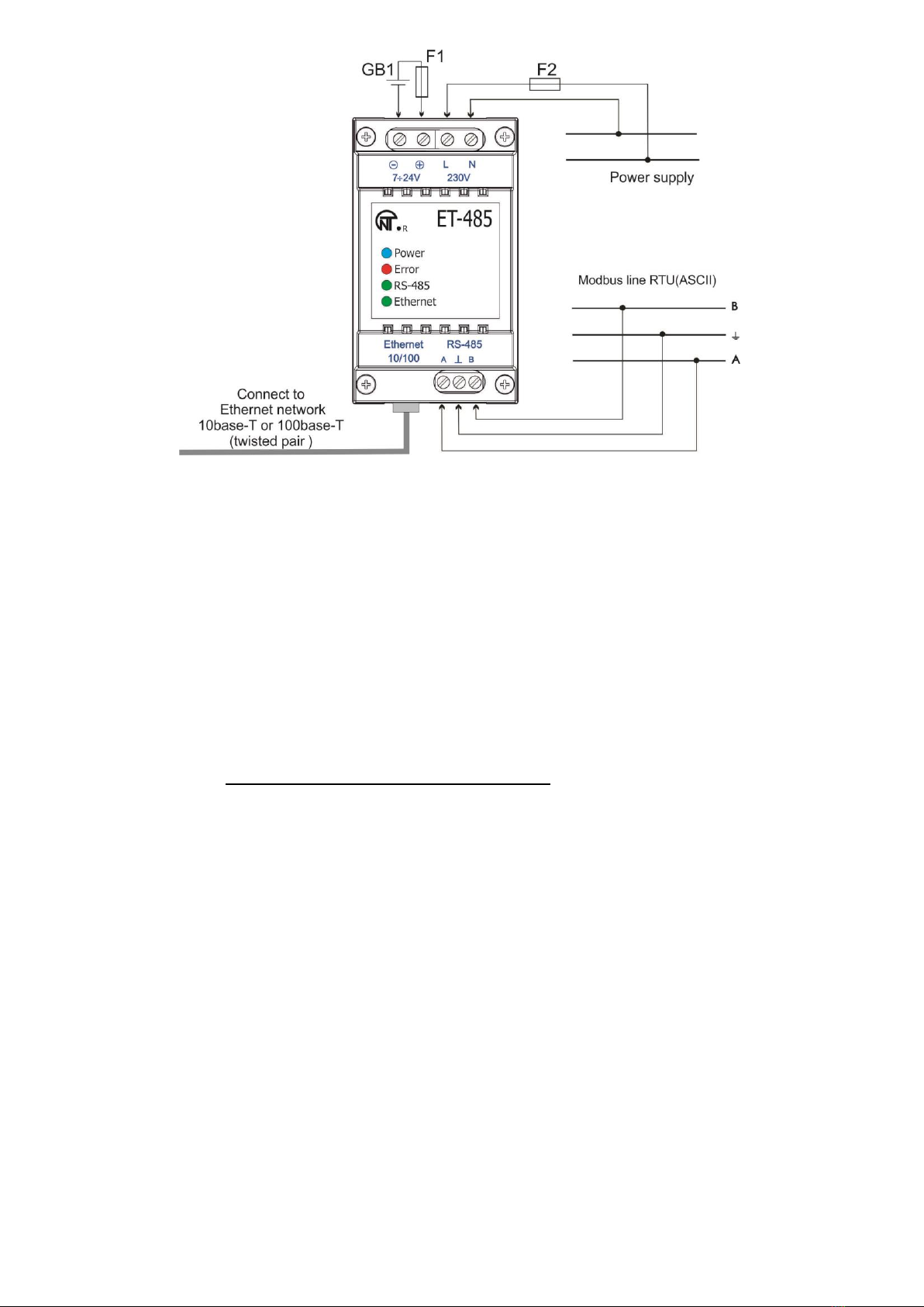
The unit is designed to provide data exchange between the equipment, connected to Ethernet 10BASE-T and
100BASE-T network, and the equipment, supplied with RS-485 interface and forming Modbus network. The
examples of network topology with application of ЕТ-485 are shown in appendix С.
In the RS-485 master mode, the unit redirects Modbus-queries from the clients in Ethernet network to the
devices in Modbus network and returns the answers from the devices to the clients. In the query redirection to
remote server mode, the unit maintains the connection to Modbus TCP server in Ethernet network and in addition
directs client queries to this server. In the RS-485 slave mode, the unit in addition accepts RS-485 queries from a
Modbus-client within Modbus network.
ЕТ-485 has:
flexible addressing within the Ethernet network (overloading MAC-address, static and dynamic IP-address);
different data transfer modes for Modbus network (RTU and ASCII with/without odd-even check, wide range
of transmission speeds, selectable delay;
adjustable redirection of queries;
security access (IP address filtration and/or access password for condition reading, for setting the unit, for
connection to Modbus network, and for recording/reading within Modbus network).
possibility to update the embedded software.
Changes in the ET-485 specifications and operation depending on version are described in appendix A.
Terms and abbreviations:
10Base-T –Ethernet standard for twisted pair communication with the speed of 10Mbit/s;
100Base-T –Ethernet standard for twisted pair communication with the speed of 100Mbit/s;
8P8C/RJ45 –is an unified socket for 10Base-T / 100Base-T network connections;
ACC - Active Connection to the Client, where connecting side acts as a server;
ASCII –is a table of standard codes for information interchange;
Client –is a device, which is addressing the other devices (server) with a request toperform certain functions;
DCRS - Data Collection Remote Server, to which ET-485 connects in the ACC mode
Ethernet –is a standard for packet network communication and transmitting data between units (e.g., PCs);
HTTP –is a protocol for transferring Web-pages and other data over "client-server " technology;
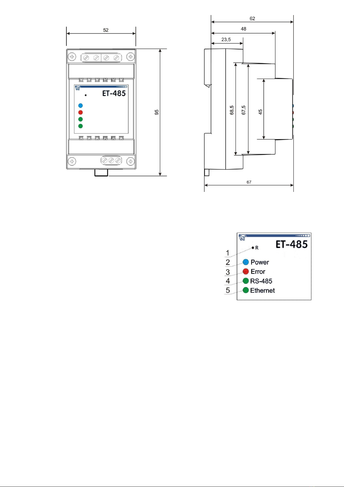
Indicator –is a LED element;
Internet –is a global routing system of units for storing and transferring data;
IP (protocol) –is a routable protocol for transferring data over Ethernet. It is a part of TCP/IP and used for
Internet;
IP (address) –is a node address, which is unique within a single network, operating over the IP protocol;
IPv4 –is a four byte IP-address;
MAC (address) –is an address, used for device authentication during Ethernet transmissions. It is usually
unique although qualified personnel can change it under certain circumstances.
MAC-48 –is a six byte MAC-address;
Modbus –is a standard and protocol for packet communication over the "client-server " technology for
industrial electronic units;
Modbus RTU –is a communication protocol of the unit for bite wise transfer of the package;
Modbus ASCII –is a communication protocol of the unit forthe transfer of package in the form of ASCII-symbols;
Modbus TCP –is a protocol for transferring Modbus packages under the TCP/IP standard;
Package –is a block of data to be transmitted between devices;
RS-485/EIA-485 –is a network standard for communicating units over the twisted pair;
Server –is a unit, which performs specific functions at the request of other units;
TCP/IP –is a standard and a set of protocols for transferring data along the networks with delivery
verification;
Twisted pair –is a pair of insulated conductors inside the cable, which are twisted together in order to reduce
the distortion of the transmitted signal;
Unit –is the ЕТ-485 Protocol converter;
WEB –is a system for accessing documents on the server, used in the Internet.
WEB-page –is a document, file, recourse, which is available on the Web-server;
WEB-browser –is a WEB-server client for accessing the WEB-pages, which is primarily using the HTTP
protocol.

~ 4~
ЕТ-485
NOVATEK-ELECTRO
2. TECHNICAL SPECIFICATIONS
2.1. MAIN SPECIFICATIONS
Main specifications are resulted in Table 1.
Table 1 –Main specifications of the unit
Parameters
ET-485
ET-485-24
Operating supply voltage, VAC
230
Voltage to maintain normal operation, V
- alternating current
- direct current
- voltage of DC backup power
100 –250
140 –350
-
100 –250
140 –350
7 –24
Supply frequency, Hz
47 –63
Data Exchange Interface over the Ethernet network
10BASE-T/100BASE-T (twisted pair)
Supported Ethernet protocols
ARP, IP, TCP, Modbus TCP, HTTP
Maximum number of connections over the Modbus TCP protocol
11
Integrated servers
Modbus-server, HTTP-server
Data Exchange Interface over the Modbus network
RS-485
Modbus network exchange modes
Driving (Master) / Driven (Slave)
Supported Modbus protocols
Modbus RTU, Modbus ASCII
RS-485 driver maximum output voltage, V
3.3
RS-485 output current of short circuit driver (limiting), mA
250
RS-485 receiver input current, mA, no more than
0.125
Integrated terminator resistance, Ohm
300
1600
Recommend number of connected units within the Modbus network:
-when receivers input current of RS-485 bus is doesn‟t more 0,125 mA
-when receivers input current of RS-485 bus is doesn‟t more 1mA
256, not more
32, not more
Indication
LED‟s
Readiness time upon switching the unit to the mains, sec, no more than
1
Rower consumption, W, not more
2.2
1.2
Weight, kg, at most
0.200
Dimensions, mm
95 х 52 х 67
Unit purpose
Control and distribution device
Nominal operation condition
continuous
Cross section of terminals connection wires, mm²
0.3 –3
Terminal screws, N*m
0.4
Level of unit protection:
IP20
Protection class against electrical shock
II
Permissible pollution density
II
Overvoltage category
II
Rated insulation voltage, V
450
Rated impulse withstand voltage, kV
2.5
Operating position
arbitrary
Pollutants in the amount, which is not to exceed the maximum
permissible concentration
None
2.2. OPERATING CONDITIONS
This unit is designed to operate under conditions resulted in Table 2.
Table 2 –Operating conditions
Operating temperature, °С
from minus 35 to +55
Atmospheric pressure, kPa
from 84 to 106.7
Relative air humidity (at 25°С), %
from 30 to 80
3. STRUCTURE AND OPERATION
3.1. STRUCTURE
3.1.1. Design
The unit has a standard plastic case, which can be attached to the DIN-rails with the width of 35 mm. The unit
drawing, together with the overall and setting dimensions, is provided in Figure 1.

~ 5~
NOVATEK-ELECTRO
ЕТ-485
Figure 1 –Overall dimensions of the unit
3.1.2. Display and control
The front panel of ЕТ-485 is provided in Figure 2.
1 –Reset button "R" (the «R»reset button (is under the body and
accessible for pressing through the opening in the body) is designed to
restart the unit or factory reset.
2 –Power indicator «Power» is activated if supply voltage is available.
3 –Error indicator «Error» warns about errors (to include format errors of
incoming data packages).
4 –Indicator «RS-485» is activated while waiting a reply from the unit in
the Modbus network; is flashing while data exchange over the Modbus
network.
5 –Indicator «Ethernet» is activated when connected to the Ethernet
network; is flashing while data exchange over the Ethernet network.
Figure 2 –Front panel of ET-485
3.2. OPERATION
Simplified structural diagram of the unit is provided in Figure 3.
32-digit RISC-processor with ARM architecture provides data routing between the Modbus RTU/ASCII
(RS-485) network and Ethernet (10base-T/100base-T) network. The operating speed and availability of channels for
direct access to the memory allows to process the high-speed data flow. Indicators provide information on the
connection status and data transfer over the Modbus and Ethernet networks.
The "Reset" button allows of restart the unit, without switching it off the mains, or do a factory reset:
to do a factory reset –press and hold down the reset button "R" for 8 seconds; "Error" indicator shall be
activated in 2 seconds; the unit shall be restarted and the indicator "RS-485" shall be activated and deactivated
after 8 seconds of holding down the button; release the "R" button;
to reset the unit while saving user configurations –press and hold down the reset button "R"; release the "R"
button when "Error" indicator shall become activated.
Note –When restarting the unit, the clients may need to renew the connections.
The unit has a memory to save settings. Every unit is provided with a globally unique MAC-address (during the
production) and can be connected to local networks with a protected access to Internet.

~ 6~
ЕТ-485
NOVATEK-ELECTRO
Figure 3 –Structural diagram of the unit
4. MAINTENANCE AND SAFETY MEASURES
4.1. SAFETY MEASURES
4.1.1 ЕТ- 485 IS OPERATING A POTENTIALLY LETHAL VOLTAGE;
Power off the unit, as well as any other units connected to it, before maintenance, trouble-shooting
or installation works.
4.1.2 The unit is not designed for operation under impact or vibration conditions.
4.1.3 Do not expose the inner electric components of the unit, as well as input contacts of terminal blocks and
sockets, to water.
4.1.4 Do not operate the unit in aggressive environment with the presence of acids, alkalies, oils, etc. in the air.
4.1.5 Switching, adjustment and maintenance of the unit should be conducted by the qualified personnel, who
is familiar with the provisions of this Operating Manual.
4.1.6 The following regulations should be enforced while operating and maintaining the unit: "Regulations for
Operation of Consumer Electrical Installations”; “Safety Rules for Operation of Consumer Electrical
Installations”; “Occupational Safety in Operation of Electrical Installations”.
4.2. MAINTENANCE PROCEDURE FOR ЕТ-485
Suggested maintenance interval –every six month.
The maintenance procedure includes visual inspection to verify the connection of cables to the ЕТ-485
terminals, as well as the absence of fractures and cracks on the case.
All safety regulations provided under section 4.1 should be enforced during the maintenance.
5. SWITCHING OF ЕТ-485
The unit is switched according to the diagram, see Fig. 4. Examples of Networks Topology for the different
solution of tasks are given in Appendix C.
Note. To improve performance of the device in power supply circuit of ET-485 it is recommended to install the
circuit breakers (fuses) F1 and F2 or their analogues for the current of no more than 1 А.
1)Switch the cable connection with Modbus network (twisted pair cable of Cat.1 or higher) to the "RS- 485" socket
and Modbus network (or directly to the unit with RS-485 interface).
Note - Contact “A” is designed for transferring non-inverted signal, while contact “B” is used for the
inverted signal.
2) Switch the cable connection with Ethernet network (supplied) to the “Ethernet” socket and Ethernet network.
Examples of the networks topology to solve different tasks are given in Appendix В.
3) In case of using mains supply, connect the cable to the mains (the cable with copper stranded wires of
section of at least 0.75 mm2and maximum operating voltage of at least 400 V) to the connector “230 V” and to the
mains.
4) In case of using the backup power or primary power supply with voltage up to 24 V DC, connect the cable to
the backup power supply (the cable with copper stranded wires of section of at least 0.75 mm2and maximum
operating voltage of at least 50 V) to the connector “7†24 V” and to the backup power source corresponding to the
unit specifications.
6. APPLICATION ЕТ-485
6.1. GENERAL INFORMATION
Powering up the unit will activate "Error" and "RS-485" indicators, while the unit shall start initiating transceivers.
After that, both indicators go out within 1 second and the unit starts working (Ethernet network connection may
take more time depending on the settings of the unit as well as other units connected to the network).
WARNING! CONTINUOUS ACTIVATION OR FLASHING OF “ERROR” INDICATOR IN THE ABSENCE
OF CONNECTIONS TO THE UNIT INDICATES UNIT MALFUNCTION.
Ethernet network connection pending. The network connection is established, if “Ethernet” indicator becomes
activated. Flashing of “Ethernet” indicator stands for transmitting data over the network.

~ 7~
NOVATEK-ELECTRO
ЕТ-485
GB1 –DC backup power source of 7†24 V, 1.2 W;
F1, F2 –fuses or their analogues of up to 1 A current;
Figure 4 –Unit connection diagram
6.2. OPERATING ЕТ-485 OVER THE HTTP PROTOCOL
ET-485 waits for a connection to an Ethernet network using the HTTP protocol on port 80. PC connection can
be established using the WEB-browser.
When a client connects to port 80, the unit starts expecting requests for HTML-pages. These requests may
contain certain parameters. In case of a valid request, those parameters are processed and the client receives the
text of a selected HTML-page. In case of a request without an indication of certain page, the client is returned to the
title page. When the page is transferred, the unit deactivates the client and awaits for further connection.
6.3. OPERATING ЕТ-485 OVER THE MODBUS TCP PROTOCOL
While operating, the ET-485 waits for a connection to an Ethernet network using the Modbus TCP protocol
on port 502. The connection port for Modbus TCP can be changed by the user. PC connection can be established
using any software –Modbus TCP of the clients. Client software for ОС Windows can be downloaded from the
manufacturer's web-site (http://novatek-electro.com/eu/software.html).
When a request for client connection to the Modbus TCP port is received, the unit starts verifying the client's IP-
address (if connection filtering over IP is activated). If this address does not correspond with the preset value, the
connection is rejected. Otherwise, the unit starts checking the list of available connections. In case of no available
connections, the unit (depending on the configuration) can connect a new client instead of the previously connected
one (if no activity of the client was registered over a set period of time, or if the connection is maintained longer than
prescribed).
When connecting the client to Modbus TCP port, the client is added to the internal list of clients in service (but
of the number no more than indicated in specifications).
When connection of the client is established, the unit awaits a Modbus-query from the client. In the mode of slave
via RS-485, it also accepts a client connection.
When the query from the client has been received, the unit analyzes the query and, depending on the
requested function code and the current rights of the client, either processes or blocks it. When the query is
blocked, ET-485 can generate and transfer the client-specified Modbus exception code (default –code 1) to the
client. The rights of the client, depending on the settings, are determined according to its IP address (the Modbus
network master IP address is considered to be 127.0.0.1) and input passwords.
If the query is addressed to ЕТ-485, the unit does not redirect the query, processes it and transfers the answer
to the client.
In the RS-485 master mode, queries to other devices are redirected to Modbus network and an answer form
Modbus network is awaited –herewith the «RS-485» indicator will start to glow. If the data have been received or
the standby time has run out, the «RS-485» indicator will go out.
In the mode of redirection to the remote server, if there is a connection with the remote server Modbus TCP in
Ethernet, then the other devices should be also accepted the connection.
Note –The answer is received from the first answering addressee, therefore there must be no devices
with same Modbus addresses (identifiers) in Modbus network and among the addressees, available through
the remote server.

~ 8~
ЕТ-485
NOVATEK-ELECTRO
If a query failed to be redirected (e.g. in the RS-485 slave mode, if connection to the remote server was broken),
ET-485 can generate and transfer the client-specified Modbus exception code (default –code 10) to the client.
If there is no answer, ET-485 can generate and transfer the client-specified Modbus exception code (default –
code 11) to the client.
If the answer to the query has been received, ЕТ-485 transfers it to the client, which sent the query.
In case of any format errors, an “Error” indicator shall become activated for 0.5 seconds and no response is
provided to the client.
6.4. THE OPERATION OF ET-485 IN THE MODE OF ACTIVE CONNECTION TO THE CLIENT
In this mode in addition to providing other connections ET-485 autonomously establishes and further maintains
active connection to the client (data collection remote server) with a set host name or IP address.
ET-485 receives Modbus TCP queries from this client and returns responses. The mode allows one user to work with
one or more ET-485 units viathe Internet without static address assignment to each unit (see Appendix C).
7. SETTING
7.1. GENERAL INFORMATION
Configurable parameters are described in section 7.2. All parameters are saved at the power off.
Unit configuration can be done in two ways:
through WEB-interface, see Section 7.3;
through Modbus-interface, see Section 7.4;
WARNING! ANY CHANGES IN UNIT CONFIGURATION MAY RESULT IN BLOCKING OR
OBSTRUCTION WHILE TRYING TO REACH THE UNIT OVER THE NETWORK.
In this case, all parameters should be factory reset (see Section 3.2).
7.2. PARAMETERS OF ЕТ-485
A collection of parameters available via Modbus protocol is provided in Table 3. The inner structure of any
collection of parameters is similar to the structure of collection, which is described in table 8 (apart from start-address).
The presentation format of parameters in Modbus registers is detailed in Table 4.
The unit describing parameters are given in Table 5.
The unit current mode parameters are available for reading and recording and specified in Table 6.
All parameters to determine the current condition of the unit (available for read-only) are provided in Table 7.
All parameters available in the configuration mode only are provided in Table 8.
ACC identification state parameters (table 9) are available for ACC and in a parameter mode.
ACC identification control parameters are available only for ACC and are described in table 10.
The user registers are available for reading and recording and they are given in Table 11.
The virtual registers are available for reading and recording and they are given in Table 12.
Table 3 –Collection of parameters available via Modbus protocol
Collection
Description
Access
Address
Acting settings
Current unit configuration
In any mode,
read-only
200–299,
1200–1241
Saved settings
The collection is saved regardless of power supply
and further used as the restart.
In configuration mode only,
read-only
300–399,
1300–1341
Factory
settings
Fixed collection, which can be activated as shown in
sections 7.3 and 7.4
In configuration mode only,
read-only
400–499,
1400–1441
Changeable
settings
All parameters listed in table 8, which can be modified
and incorporated as described in Section 7.4
In configuration mode only,
reading and writing
500–599,
1500–1541
Table 4 –Presentation format of parameters in Modbus registers
Parameter
Range of values
Description
Number of
Registers
Number
0 –65535
Integer (16 bits) in a standard range of Modbus register
1
Number
0 –4294967295 in two
registers, upper part –first
Integer number, which cannot exceed the limit for
Modbus register (65535)
2
Character
string
In every register number
from 0 to 255 –ASCII
character code or 0 (end of
string)
The set of values, each one of which is equal to code 1
of one a symbol in ASCII code.
If the string is shorter than maximum length, last
character is followed by the code 0.
Maximum length
of the string for
the given
parameter
IP-address
(IP-mask)
In every register –one byte
(0-255)
A set of four byte IPv4 address, from left to right
4
MAC-
address
In every register –one byte
(0-255)
A set of six byte MAC-48 address, from left to right
6

~ 9~
NOVATEK-ELECTRO
ЕТ-485
Table 5 –The Unit Describing Parameters
Parameter
Description
Address
Unit type
Code identifying the Modbus unit by the manufacturer (12 –ET-485)
0
Firmware version
Version of firmware of the integrated software of the unit
1
Table 6 –The Unit Current Mode Parameters
Parameter
Min –Max
Initial value
Description
Address
Entering
password
String of
characters
0
When a valid password is input, the corresponding permit is
given to the client (see registers 543-580).
When an empty string is input, the rights of the client are reset
to the level of rights at the moment of connection.
100 –
119
Control
command
0 –444,
writing in the
configuration
mode
0
0: no activity
1: «Restart» – unit restart
2: «Save» – save the changed settings on the Modbus
444: «Factory reset» – reset the unit to factory settings
120
Table 7 –Parameters to determine the current condition of the unit
Parameter
Description
Address
Mode
(more detailed see register 141)
0: User mode
1: Configuration mode
121
Current IP-address
IP-address of the unit in Ethernet network
122–125
Current MAC-address
MAC-address to authenticate the unit in Ethernet network
126–131
Number of Modbus TCP clients
Number of connections provided over the Modbus TCP protocol
132
Modbus TCP clients limit
Total number of Modbus TCP connections (herewith, one
connection is always reserved for the main client)
133
Time, min
Number of minutes since the start
134–135
Modbus TCP loading, requests/sec
Number of requests processed in a second
136
Number of Ethernet network
congestions
Number of input buffer overflows for Ethernet –from the moment
of start-up
137
Number of communication errors
Number of identified errors (connection/communication) after
which the work was continued, - since the start
138
Number of programmed resets
Number of resets according to user‟s setting – during all working
time of the unit
139
Number of critical errors
Number of identified errors (failures) resulting in a restart of the
unit - during the whole period of operation
140
Access mode flags
Bit 0
0: the connected client cannot get the permit for requesting
functions of non-recording the devices, connected to ET-485
1: the connected client can get the permit for requesting
functions of non-recording the devices, connected to ET-485
141
Bit 1
0: the connected client does not have the permit for
requesting functions of non-recording the devices, connected
to ET-485
1: the connected client has the permit for requesting
functions of non-recording the devices, connected to ET-485
Bit 2
0: the connected client cannot get the permit for requesting
functions of recording the devices, connected to ET-485
1: the connected client can get the permit for requesting
functions of recording the devices, connected to ET-485
Bit 3
0: the connected client does not have the permit for requesting
functions of recording the devices,connected to ET-485
1: the connected client has the permit for requesting
functions of recording the devices, connected to ET-485
Bit 4
0: the connected client cannot get the permit for access to
ET-485 registers, except for registers of version, password,
mode and access flags
1: the connected client cannot get the permit for access to
ET-485 registers, besides registers of version, password,
mode and access flags
Bit 5
0: the connected client does not have the permit for access to
ET-485 registers, except for registers of version, password,
mode and access flags

~ 10 ~
ЕТ-485
NOVATEK-ELECTRO
Table 7 (continued)
Parameter
Description
Address
Access mode flags
1: the connected client has the permit for access to ET-485
registers, except for registers of version, password, mode and
access flags
141
Bit 6
0: the connected client does not have the permit for
requesting function of recording ET-485
1: the connected client has the permit for requesting
function of recording ET-485
Bit 7
0: the connected client does not have the permit for setting
ET-485
1: the connected client has the permit for setting ET-485
(similar to register 121)
Bit 8
0: the client is not the main client
1: the client is the main client
Bit 9
1: the client has the right for connection
(always read as “1” after connection)
Bit
10
0: the client is connected not by ACC
1: the client is connected by ACC
Maximum of Modbus TCP clients
Maximum observed number of Modbus TCP clients (from the
moment of start-up)
142
Maximum of queries, queries/sec
Maximum observed load of Modbus (from the moment of start-up)
143
Frequency of answered queries,
queries/sec
Number of processed queries per second, to which the answer is
formed without any errors
144
Time before connection to Modbus
TCP remote server
0: connection to remote server established
1: connection to remote server is being established
2 –65534: number of seconds to repeated connection
65535: redirection to remote server is off
145
Time before active connection to
the client (or DCRS)
0: ACC is established
1: ACC is being established;
2 –65534: number of seconds to repeated ACC
65535: ACC is off
146
Table 8 –Unit configuration settings
Parameter
Min –
Max
Factory
setting
Description
Address
Ethernet network
Static IP-
address
IP-
address
192.168.0.111
IP-address of the unit in Ethernet network shall be equal to
this value if dynamic addressing is disabled or not available.
500–
503
Subnet mask
IP-mask
255.255.255.0
Used only with static IP address
504–507
Gateway
IP-
address
192.168.0.1
Used only with static IP address or as an IP filter for
DHCP server
508–
511
Dynamic
addressing
mode using
DHCP server
0 –2
1
0: preset IP-address, mask and gateway is used for
addressing in Ethernet.
1: the device uses the DHCP server of the network to
determine the gateway, mask and masked part of the IP
address, which means the network. The rest of the
address is used from the specified static address. If the
server is unavailable, the static addressing values are
used.
2: the device uses the DHCP server of the network to
determine the gateway, mask and IP address.
512
Enable IP-
address filter of
the DHCP server
0 –1
0
Used if dynamic addressing is enabled.
0: unit receives addressing data from the first DHCP-
server to respond
1: unit receives addressing data only from DHCP-server
with IP-address of the gateway
513
Enable manually
set MAC-address
0 –1
0
0: a unique value is used as MAC address for each unit
1: manually set value is used for MAC-address
514
Manually set
MAC-address
MAC-
address
Unique for
every unit
Used if manually set MAC-address is enabled for the
authentication of unit in the Ethernet network
515 –
520
Client Switching to Ethernet network
Connection port
for Modbus TCP
1 –
65535
502
Used in case of TCP-connection to the unit via Ethernet to
exchange data over Modbus TCP protocol
521

~ 11 ~
NOVATEK-ELECTRO
ЕТ-485
Table 8 (continued)
Parameter
Min –
Max
Factory
setting
Description
Address
IP-address of
the primary
client
IP-
address
192.168.0.2
IP-address, for which one connection via Modbus TCP is
reserved. Address, which is used for unit configuration. In
the RS-485 slave mode, one should specify the address
127.0.0.1 for the mail client, connecting by RS-485.
522–
525
Enable the IP-
connections
filter for
configuration
0 –1
0
0: setting parameters via Modbus-interface or WEB-
interface from any address (password protected)
1: setting parameters via Modbus-interface or WEB-interface
is only allowed from the IP-address of the main client
526
Enable the IP-
connections fil-
ter over Modbus
TCP
0 –1
0
0: Modbus TCP connections are available from any
address
1: any Modbus TCP connections are available only from
the IP-address of the main client
527
Enable
replacement of
non-active
clients
0 –1
1
0: Modbus TCP connection is maintained regardless of
the time period between requests from the client
1: if all connections to Modbus TCP are busy, the new
client, requesting for a connection, can be connected
instead of the client, who provided no requests over the
longer then preset period
528
Maximum query
timeout, sec
0 –9999
90
Used, if replacement of non-active clients is enabled
529
Enable the queue
for the last busy
Modbus TCP
connection
0 –1
0
0: Modbus TCP connection is maintained regardless of
the connection hold time
1: if all connections to Modbus TCP are busy, the new
client, requesting for a connection, can be connected
instead of the last connected client, if the hold time is more
than a preset time
530
The maximum
hold time of the
last connection to
Modbus TCP,
msec
0 –
600 000
60 000
Used, if the queue is enabled for the last connection to
Modbus TCP
531–
532
Modbus network
Own Modbus-
identifier of the
unit
0 –247
111
0: unit forwards all Modbus TCP requests into the
Modbus network, unit registers via Modbus TCP are
unavailable
1–247: units responds to Modbus TCP requests bearing
the given Modbus-identifier without forwarding them to
the Modbus network
533
Bit rate in
Modbus-network,
bit/sec
75 –
921 600
9 600
Used in case of data exchange between the units in
Modbus-network, the same value for all units in Modbus-
network
534–
535
Enable selection
of byte format in
Modbus network
0 –1
0
Used during data exchange with devices in Modbus
network, the same value for the devices in the same
Modbus network
0: There is no parity bit; 2 stop bits;
1: Byte format is selected in register 537
536
Byte format in
Modbus network
0 –5
0
Used during data exchange with devices in Modbus
network only if the byte format selection is enabled. The
same value for the devices in the same Modbus network
0: Parity check and 1 stop bit;
1: Imparity check and 1 stop bit;
2: Parity bit is always “0” and 1 stop bit;
3: Parity bit is always “1” and 1 stop bit (this mode is the
same as the mode with two stop bits);
4*: There is no parity bit, 1 stop bit;
5*: There is no parity bit, 2 stop bits when sending and 1
stop bit when receiving (this mode provides compatibility
with devices containing both 1 and 2 stop bits in the
same Modbus network)
537

~ 12 ~
ЕТ-485
NOVATEK-ELECTRO
Table 8 (continued)
Parameter
Min –
Max
Factory
setting
Description
Address
Response time
from Modbus
RTU, msec
0 –
60 000
200
Used in case of data transfer via the Modbus-network in
RTU mode. Waiting for a response is terminated if the first
byte of the response has not been received within the given
time after sending the request. The response is always
expected longer then time of silence between frames (time
of silence depends on the bit rate and shall be equal to the
time required for transmitting 3.5 bytes, or 1.75 msec for bit
rate over 19200 bits/sec).
538
Enable ASCII
exchange in
Modbus network
0–1
0
Exchange mode in Modbus-network, the same value for
all units in Modbus-network
0: RTU exchange mode (format: 1start bit, 8 data bits, 1
parity bit or stop-bit or 1 stop bit –total 11 bits).
1: ASCII exchange mode (format: 1start bit, 7 data bits, 1
parity bit or stop-bit or 1 stop bit –total 10 bits).
539
Response time
for subsequent
Modbus ASCII
character, msec
0 –
60 000
1000
Used in case of data transfer via the Modbus-network in
ASCII mode. Waiting for a response is terminated if the
subsequent byte of the response has not been received
within the given time, as indicated for the reception of res-
ponse. Waiting time shall not be less then time required for
transmission of a single character (depending on the bit
rate).
540
Miscellaneous
Enable the unit
automatic reset
0 –1
0
0: automatic reset is off
1: the unit is reset after a preset time interval
541
Unit restart
interval, min
5 –7200
7200
Used if periodic restart of the unit is enabled
542
Password to
enter the setup
mode
String of
charac-
ters
11111
Used to access the setup mode for Modbus TCP. Any
string of 5 to 20 characters can be used as a password. It
may not contain spaces or special characters listed in
quotes below: «; : " < > * + = \ | / ? ,»
543–
562
The preset
password for
permit to record
to devices,
connected to
ET-485
Symbol
string
Used for access to the devices, connected to ET-485, for
requesting functions of recording or control, which can
change the state of these devices. As a password one
may specify a string with length up to 6 symbols. The
string must not contain any spaces or special symbols,
given below in quotes: “; : " < > * + = \ | / ? ,”
563–568
The preset
password for
permit to read
from devices,
connected to
ET-485
Symbol
string
Used for access to the devices, connected to ET-485, for
requesting functions of reading, which do not affect the
state of these devices. As a password one may specify a
string with length up to 6 symbols. The string must not
contain any spaces or special symbols, given below in
quotes: “; : " < > * + = \ | / ? ,”
569–574
The preset pas-
sword for access
to ET-485
registers of state
and settings
Symbol
string
Used for access to ET-485 registers, except for the
registers of version, password, mode and flags. As a
password one may specify a string with length up to 6
symbols. The string must not contain any spaces or
special symbols, given below in quotes:
“; : " < > * + = \ | / ? ,”
575–580
Enable the
automatic reset
mode only at
downtime
0 –1
0
Used when the automatic reset is on.
0: the unit is reset after a preset time interval from the
moment of start-up
1: the unit is reset after a preset time interval from the last
query processing
581
Mail client port
0 –
65535
0: not checked
1–65535: port is used with IP address to identify the main
connected client. In the RS-485 slave mode, if the main
client is connected by RS-485, this parameter is not used.
582
Enable Modbus
write protection
mode
0 –1
0
0: write protection is adjusted by means of other
parameters or is off
1: all function queries from all clients are blocked, except
Modbus functions 1, 2, 3, 4, 7, 17, 20
583

~ 13 ~
NOVATEK-ELECTRO
ЕТ-485
Table 8 (continued)
Parameter
Min –
Max
Factory
setting
Description
Address
Enable IP
connection filter
to record to de-
vices, connected
to ET-485
0 –1
0
Used for access to the devices, connected to ET-485, for
requesting functions of recording or control, which can
change the state of these devices.
0: IP filter is not used
1: IP filter is on
584
Enable IP
connection filter
to read from
devices, connec-
ted to ET-485
0 –1
0
Used for access to the devices, connected to ET-485, for
requesting functions of reading, which do not affect the
state of these devices.
0: IP filter is not used
1: IP filter is on
585
Enable IP con-
nection filter for
access to ET-485
registers of state
and settings
0 –1
0
Used for access to ET-485 registers, except for the
registers of version, password, mode and flags.
0: IP filter is not used
1: IP filter is on
586
Enable RS-485
slave mode
0 –1
0
0: Driving mode (Master). RS-485 is used to send
queries, received from clients of Modbus TCP.
1: Driven mode (Slave). RS-485 is used to receive
queries from additional client, having IP address
127.0.0.1
587
Enable the
Modbus TCP
remote server
query redirection
mode
0 –1
0
0: queries are not sent to remote server
1: queries are additionally sent to Modbus TCP remote
server, which is “integrated” into Modbus network of this
ET-485 unit. The answer is accepted from the first
answering addressee.
588
IP address of
Modbus TCP
remote server
IP address
192.168.0.112
Used in the Modbus TCP remote server query redirection
mode. IP-address of the remote server, wherewith
connection is maintained.
589–592
Modbus TCP port
of remote server
0 –
65535
502
Used in the Modbus TCP remote server query redirection
mode. Remote server port for Modbus TCP connection.
In active mode –the port of the remote server to connect
via Modbus TCP, in passive mode –the port to connect
to the remote server;
593
Standby time to
repeated connec-
tion to Modbus
TCP remote
server, seconds
0 –
30 000
20
Used in the Modbus TCP remote server query redirection
mode. After connection with the server is lost, the
repeated connection will be established after a preset
standby time (after unit start-up, the first connection is
established in the fixed time interval of 5 seconds)
594
Standby time to
answer from Mod-
bus TCP remote
server, msec
0 –
60 000
1000
Used in the Modbus TCP remote server query redirection
mode. After the query transfer, if the correct answer failed
to be received within this time interval, answer awaiting is
stopped.
595
Modbus code of
exception,
generated at
access ban
0 –255
1
0: At ban of the access to Modbus registers of the unit or
connected devices, the answer is not returned to the client.
1-255: At access ban, this exception code is returned to
the client, which sent the query.
596
Modbus code of
exception, gene-
rated at absence
of connection to
query addressee
0 –255
10
0: If there is no connection to the query addressee
(Gateway Path Unavailable), the answer is not returned
to the client.
1-255: If there is no connection to the query addressee,
this exception code is returned to the client.
597
Modbus code of
exception, gene-
rated at absence
of answer from
query addressee
0 –255
11
0: If there is no answer from the query addressee (Gateway
Timeout), the answer is not returned to the client.
1-255: If there is no answer from the query addressee,
this exception code is returned to the client.
598
Enable passive
mode to connect
to the remote
server
0 –1
0
Used only if redirection to the remote server is enabled;
0: ET-485 connects and maintains the connection to
Modbus TCP server;
1: ET-485 waits for connection to the remote server (this
mode is not fully compatible with ModbusTCP, but it is
599

~ 14 ~
ЕТ-485
NOVATEK-ELECTRO
Table 8 (continued)
Parameter
Min –
Max
Factory
setting
Description
Address
compatible with the mode of active connection to the client,
if that modeisenabled on the sideof the remote server;
ACC settings
Enable using of
DNS server with
gateway IP
address
0 –1
1
Used when DHCP is not available (is off)
0: DNS of gateway is not used
1: DNS of gateway is used to identify client (or DCRS) IP
ad-dress for active connection, if its address is set as host
name
1500
Enable using of
DNS server with
manually set IP
address
0 –1
1
Used when DHCP is not available (is off)
0: DNS with manually set IP is not used
1: DNS with manually set IP is used to identify client (or
DCRS) IP address for active connection, if its address is
set as host name
1501
Manually set IP
address of DNS
server
IP
address
8.8.8.8
Used when manual address of DNS server is enabled in
order to identify client (or DCRS) IP address for active
connection, if its address is set as host name
1502–
1505
Enable active
connection to
the client
0 –1
0
0: active connection to the client is not used
1: Modbus queries are also received from the client (or
DCRS) with set address, to which ET-485 establishes
and maintains connection. This client recieves rights of
the second primary ET-485 client
1506
Enable sending
of unique MAC
address of the
unit after active
connection to
the client
0 –1
1
Used in the mode of active connection to the client.
0: automatic sending is not accomplished
1: after active connection to the client the unit once
sends 1000–1010 registers contents in the form of
Modbus response without client query (reading by
function 3)
1507
Timeout until
repeated active
connection to
the client, sec
0 –
30 000
20
Used in the active connection to the client mode. After
loss of active connection to the client, repeated
connection will be established after present connection
timeout (after setting of the unit the first connection is
established after the fixed time interval of 5 seconds).
1508
Client port (or
DCRS) for ac-
tive connection
0 –
65535
20502
Used in the mode of active connection to the client.
Client (or DCRS) port, to which ET-485 establishes
active connection.
1509
Client (orDCRS)
address for ac-
tive connection
Symbol
string
modbus.
overvis.com
Used in the mode of active connection to the client. IP
address (or host name) of the client or DCRS for active
connection
1510–
1541
* –byte formats 4 and 5 are non-standard for Modbus and can be used only in Modbus RTU mode;
Table 9 –State of unit identification for ACC
Parameter
Description
Address
Unit type
see register 0
1000
Firmware version
see register 1
1001
Unique MAC address
Globally unique MAC address of the unit, which can be used for
identification by the client
1002–
1007
ACC state flags
Bit 0
0: 0: error of unique MAC address reading
1: registers 1002–1007 contain globally unique MAC
address
1008
Bit 1
0: 0: activation code on the data collection server is not set
1: activation code on the data collection server is set
Bit 2
0: ET-485 doesn‟t require new activation code from server
1: ET-485 requires new activation code from server
Bit 3
0:connection is notactivated by the data collection server
1:connection is activated by the data collection server

~ 15 ~
NOVATEK-ELECTRO
ЕТ-485
Table 10 –Unit identification control for ACC
Parameter
Min.–Max.
Initial value
Description
Address
Activation
code on the
data
collection
server
10 000 000 –
100 000 000
or 0
100 000 000
Code, transferred from data collection server and displayed
on the unit setting page through WEB interface (p. 7.3).
When user enters the code on the data collection server, the
unit and ACC connection become available to this user.
0 –connection is activated;
10 000 000 –99 999 999: activation code; 100 000 000:
code is not assigned
1009 –
1010
Table 11 –User registers
Parameter
Initial value
Description
Address
User
0
These registers are stored in RAM and are not used by ET-485.
The registers can be used at the discretion of the user;
5000–5249
Table 12 –Virtual registers
Parameter
Description
Address
Virtual
When accessing these registers ET-485 transmits the request to the other device.
The real identifier of Modbus and address of the registers depends on the address
of the virtual register:
<Virtual register address> = 5000 +
1000 * <Modbus identifier> + <real address of the register>
6000 –
37999
7.3. CONFIGURING ЕТ-485 THROUGH WEB INTERFACE
WEB-browser is used for setting via WEB-interface.
Write the unit IP-address in your browser (factory setting - 192.168.0.111) and proceed to the specified address.
Note - If the browser is set to use the proxy server, the access to the unit over local network shall be granted only after
adding the IP- address into the exceptions list as indicated in the browser documentation.
This will open home page with tabs for transferring into the other modes.
Select “Settings” to start the configuration of unit Ethernet network.
Password request shall appear before granting access to setup mode (factory setting 11111).
Enter password and press "Enter". If the password is correct, you shall be granted access to the setup mode.
Settings page appears with a list of parameters detailed in Table 8. If the password is incorrect, the password
request shall be displayed once again.
Click "Save" after making changes to the settings. This will check all the changed parameters. If no errors is
detected, new parameters will be stored in the memory (new parameters will become effective upon the following
restart/activation of the unit). In case of any errors detected upon clicking the "Save" button, none of the parameters
is saved, while the names of erroneous parameters are highlighted in red.
Click "Factory reset" to restore the default value of parameters.
Click "Restart" to stop all connections and interrupt all receive/transmit operations, with the following restart of
the unit. In case of any changes to the parameters, either introduced or stored in the memory, these changes shall
be implemented.
Note - If the addressing parameters in Ethernet network (MAC-address, IP- address, DHCP settings) are modified and
saved, the browser may not load the page after the restart of the unit by pressing the “Restart” button. This can happen as the
browser continues to reply over the previous address. In this case, the connection should be made anew.
Clicking the “Exit” button the will close the setup mode and a password request appears once again.
7.4. CONFIGURING ЕТ-485 THROUGH MODBUS INTERFACE
Setting via Modbus-interface shall be provided if the unit is connected over the Modbus client, which is
supporting the Modbus TCP protocol. The connection is established using its IP-address (factory setting –
192.168.0.111) with the indication of Modbus-identifier (factory setting –111). In the RS-485 slave mode, he setting
can also be performed by the master device in Modbus network.
To set the parameters, one should write the password string into the password input parameter (table 6).
The factory password value is 11111, so to write the factory password into the registers from 100 to 104 one
should write the number 49 –the ASCII code of figure one. If the password is specified correctly, the mode
parameter (table 7) obtains the value 1 –the setting mode.
In the setting mode, the control command parameter (table 6) as well as the setting parameters (listed in Table 8)
are available for recording. After the necessary values settings are recorded into the parameter registers, one should
write the value 2 –“Save” command – into the control command parameter. The correctness of the saved parameter
values can be checked by comparing the sets of adjustable parameters with the saved parameters. If the sets match
each other, the new values of settings are accepted and saved.
To reset the saved parameters to factory values, one should write the value 3 –“Return to Factory” command
–into the control command parameter in the setting mode.
In order to make the saved parameter values come into effect, the unit must be restarted. By means of Modbus
interface, the restart is performed by writing the value 1–“Restart” command – into the control command parameter

~ 16 ~
ЕТ-485
NOVATEK-ELECTRO
To exit the setting mode, one should write 0 into the first register of password input parameter. Herewith, all the
password input registers and the control command parameter register are cleared (obtain 0 value).
8. COMPLETE SET
ET-485 is supplied with:
- ET-485 protocol converter.....................................................1 piece
- Operating manual .................................................................1 piece.
- Cable for Ethernet connection...............................................1 piece
- Shipping box..........................................................................1 piece
9. SERVICE LIFE AND WARRANTY
9.1. Service life –is 10 years. Contact manufacturer upon the expiry of the service life.
9.2. Guaranteed storage life –is 3 years.
9.3. Warranty period –is 5 years from the date of sale.
During the warranty period the Manufacturer is responsible for free repair of the unit, if the Consumer has
complied with the requirements of this Operating Manual.
ATTENTION! IF THE UNIT HAS BEEN OPERATED WITH VIOLATION OF THE REQUIREMENTS OF THIS
OPERATING MANUAL, BUYER WILL FORFEIT THE RIGHT TO WARRANTY SERVICE.
9.4. Warranty service is performed at the place of purchase or by the Manufacturer of the product.
9.5. Post-warranty service is performed by the Manufacturer at current rates.
9.6. Before sending for repair, the unit should be packed in the original or other packaging excluding mechanical
damage.
Earnest request: indicate the reason for return in the notice of faults field at the return of the device or in case of
submitting for warranty service or post-warranty service.
10. TRANSPORTATION AND STORAGE
ET- 485 in the shipping box should be stored indoors at a temperature of -50 to +60 °C and relative humidity of
no more than 80% with no vapors available in the air, capable of producing harmful effect on the shipping box and
unit materials. When transporting ET- 485, the user should provide some protection against mechanical damage
11. ACCEPTANCE CERTIFICATE
ET-485 is manufactured and accepted in accordance with the applicable technical documentation and
considered fit for use.
Stamp Head of quality division Date of manufacture
__________________ _________________
12. DATA ON CLAIMS
________________________________________________________________________________________
________________________________________________________________________________________
________________________________________________________________________________________
________________________________________________________________________________________
________________________________________________________________________________________
________________________________________________________________________________________
________________________________________________________________________________________
________________________________________________________________________________________
________________________________________________________________________________________
________________________________________________________________________________________
The Company is grateful to you for the information about the quality of the unit and suggestions for its operation.
For all questions, please contact the manufacturer:
NOVATEK-ELECTRO Ltd, Tel.: +38 (048)738-00-28,
59, Admiral Lazarev Str., Tel./fax: +38 (0482) 34-36-73.
Odessa, 65007, Ukraine. www.novatek-electro.com
Date of sale___________________ VN190328

~ 17 ~
NOVATEK-ELECTRO
ЕТ-485
APPENDIX A
(obligatory)
Versions and changes
Firmware versions and changes are listed in table A.1.
Hardware versions are listed in table A.2.
Table A.1 –Firmware versions and changes
Version
Release date
Remarks
7
10/11/2013
First released version
9
12/24/2013
Changes in some Ethernet modes (added optional powering the device with
unplugged Ethernet cable, hot disconnection/reconnection of the cable)
10
3/24/2014
Added events/errors counters;
Added device periodical reset option
11
4/22/2014
Additional mode “RS-485 Slave + Modbus TCP client”;
Added option for Modbus write protection
12
5/14/2014
Additional mode “Modbus TCP client (redirection)” is made as separate option;
Added security settings (Modbus read/write passwords, TCP ports filters);
Automatic restart can be programmed to trigger only when idle for specified
time
13
5/21/2014
Device additional modes options are available in HTTP interface
15
6/6/2014
Added TCP redirection in RS-485 Master mode
Added firmware version number to HTTP interface home page
16
8/7/2014
Added active connection to client (ACC) mode for switching to device with
dynamic IP address (e.g. from Overvis);
New HTTP interface to view state and setup options of the device via WEB
browser;
Improved crashproofness when functioning for a long time without restarts
17
9/2/2014
Changed password test (added possibility to set multiple passwords which are
alike)
18
10/16/2014
Changed Modbus clients sessions policy (password-granted rights are kept
active for set period of time, for clients accessing not ET-485 but other
Modbus devices)
20
22/01/2015
The option of updating the integral Software has been added
23
20/02/2016
The non-standard byte formats are added when data exchanging via RS-485;
The user register field is added;
The virtual register field is added;
The passive mode to connect to the redirecting server for Modbus is added
25
30/03/2018
The fail-safe feature is improved in busy Ethernet networks
27
01/08/2018
The fault tolerance is improved in case of electromagnetic interference
DHCP Dynamic Subnet mode is added
29
03/28/2019
Improvements for setup mode via WEB browser
Table A.2 –firmware versions and changes
Version
Release date
Comments
1
10/11/2013
First released version
2
4/12/2014
Changed RS-485 driver to increase number of connected devices;
Changed labeling (added contacts “L” and “N” labeling)
3
22/01/2015
The brightness of signal “Power” has been reduced;
The option of saving the files of integral Software updating has been added.
4
15.12.2016
ET-485-24 version

~ 18 ~
ЕТ-485
NOVATEK-ELECTRO
APPENDIX B
(recommended)
SWITCHING TO ETHERNET
WARNING! Switching the unit to Ethernet network requires mutual coordination of settings on the
connected devices. Connecting the misconfigured unit to the network may affect the
communication level of other units on the network. As a rule, all connections to a network of more
than 2 units are carried out by the qualified personnel (network administrator) only.
1. IP-ADDRESSING
When units are communicating over Ethernet network using TCP/IP protocol, every unit is using a set of IP-
addressing settings to identify the sender and receiver of the data. The unit memory contains a personal and
unique, within a single subnet, IP-address (four bytes are written as four integers, separated by dots, in the range of
0-255), subnet mask, which is the same for all units within the subnet (written similar to IP-address), and IP-address
of the gateway, which is used to communicate with other networks. Proper communication between units of a
subnet is possible under several conditions:
1) All units of a subnet have similar mask. Most of small LANs are using 255.255.255.0 mask.
2) Mask starts with a group of bits set to 1, followed by a group of bits turned to 0.
3) All bits set to 1 in the mask are similar for all the IP-addresses of units in subnet and indicate the subnet
address. 192.168 is most frequently used address in LANs for the mask 255.255.255.0. The third byte may be used
as a subnet number in a complex LAN. In smaller LANs, the third byte is usually equal to 0.
4) A set of bits in IP-address of the unit, which is set to 0 in the mask, is unique to each unit within the same
subnet .
5) In most cases, the unit like router, which is already communicating with other networks, is switched to the
network. This unit often gets the following address 192.168.0.1, 192.168.0.100, or 192.168.0.101. In this case, other
units in the network shall have this IP-address of the unit as the gateway address. This address is not necessary for
communication between units in a subnet, and is only used to connect units of one subnet to units of other networks.
Factory addressing settings for ET-485 Interface Converter are listed in Table B.1.
Table B.1 –Factory settings for ET-485 addressing
Parameter
Value
IP-address
192.168.0.111
Subnet mask
255.255.255.0
Gateway
192.168.0.1
Dynamic addressing mode with DHCP
1 ("dynamic subnet")
With the factory settings of ET-485, there are 2 ways to communicate with it:
a) the network uses a router or other DHCP server that assigns IP addresses to new devices, and the address
consisting of a masked subnet portion of the DHCP server and a non-masked part of the factory IP address of the
device is free in the network. In this case, it is enough to connect ET-485 to this network, and after a few seconds
ET-485 will be available at this address. For example: the subnet address of the DHCP server is 192.168.1, the
mask is the same as the factory value of the device. In this case, the address occupied by ET-485 in this network is
192.168.1.111. If the subnet settings from the DHCP server could not be obtained, the device will use the factory
address;
Note - the subnet address and mask can be obtained from the network administrator, or from the
connection status of any device in the network. For example, by opening the list of network connections, as
described in B.2, right-click on the network connection icon and select "Status".
b) the address that the ET-485 can occupy is busy in the network, it is not possible to use DHCP, or the ET-485
is connected directly to the computer (or other client device). In this case, the ET-485 will switch to static addressing
after some time (10-15 seconds) after starting. The client device must use the mask 255.255.255.0 and the address
starting with 192.168.0. The fourth byte of the address can take any value in the range from 1 to 255, except for 111.
If the connection between ET-485 and a client unit is not provided directly but via a network with a number of units, the
mentioned address cannot be equal to any of the addresses of other units on the subnet 192.168.0. To avoid
addressing conflicts, it is recommended to temporarily disable the configurable client device and the device from the
network to connect the client device and the device directly. This will allow to configure the unit and ET-485 for direct
communication or switching ET-485 to the network.
2. CONFIGURING THE CLIENT UNIT
The unit addressing is set according to documents and software it uses.
Below is an example of configuring the personal computer (PC) on Windows XP/7/8/10 to communicate directly
with the ET-485 on factory settings.
Open the list of OS network connections to configure the network address in Windows. To do this, follow the
steps below (mind the OS version):

~ 19 ~
NOVATEK-ELECTRO
ЕТ-485
For Windows XP:
1) Log in as administrator.
2) Select “Start-Control Panel”.
3) If control panel items are divided into categories, select "Network and Internet Connections".
4) Go to "Network Connections".
For Windows 7/8/10:
1) Log in as administrator.
2) Select “Start-Control Panel”.
3) If control panel items are divided into categories, select "Network and Internet".
4) Go to "Control Center Network and Sharing Center".
5) In the task bar (on the left), select "Change adapter settings".
Next, perform the following steps:
1) In the Connections window, select the desired connection via an adapter with the addressing that you want
to change. Many computers have only one adapter and one connection, which will be displayed in this
window. If the window shows several connections, select the connection you want , using the adapter name
in the information on connection or contact your system administrator.
2) Click the icon of the connection with the right button, and select "Properties" in the drop-down menu. The
Properties window opens (see Fig. B.1).
3) Select "Internet Protocol (TCP/IP)" from the list of connection components in the open window (for OS
Windows 7/8/10 –“Internet Protocol version 4 (TCP/IPv4)”. Make sure that the component is enabled
(flagged in the list). Click "Properties". The TCP/IP properties window opens (see Fig. B.2).
4) Select "Use the following IP- address".
5) Specify the address in the "IP- address" field within the range from 192.168.0.1 to 192.168.0.255 (except for
192.168.0.111, which is used by ET-485).
6) Specify "255.255.255.0" in the “Subnet Mask” field.
7) The fields "Default Gateway", "Preferred DNS-server", and "Alternative DNS- server" should be left blank.
8) Press "OK" to close the Protocol Settings window.
9) Press "OK" to close the Connections Settings window.
10) If prompted by the OS to restart the PC after closing the windows, answer yes.
Figure B.1 –Connection properties Figure B.2 –TCP/IP properties
window in Windows OS window in Windows OS
3. SWITCHING TO INTERNET
WARNING! The user is strongly recommended to connect the unit to Internet under the
supervision of the LAN system administrator and/or representative of Internet service provider.

~ 20 ~
ЕТ-485
NOVATEK-ELECTRO
Use the following guidelines to connect the unit to Internet:
acquire a dedicated line with a static IP-address from your Internet Service Provider (hereinafter referred to as
–ISP; for connection with dynamic IP address it is necessary to use active connection to the client);
direct connection of the unit to the ISP cable is not recommended. In case of a router connection, the ISP
cable is connected to the "Uplink" socket on the router (It is usually marked with color and has no numbers. The
marking depends on the router manufacturer, see the router documentation). The straight-through (supplied)
Ethernet cable is used for connecting unit to the router. Set the router for Internet connection as per ISP
recommendations using the router documentation. The router settings should also provide for the redirection of
requests, which are coming to static IP-address provided by the ISP, to the unit IP-address (factory setting -
192.168.0.111). If for a dedicated line the static IP address is fixed in Internet, and direct access from Internet to
WEB (HTTP) and MODBUS TCP interfaces is required, then in settings of a router it is required to specify ports of
redirection (forwarding) –for a local IP address of a product on which redirection is set up, it is necessary to specify
port 80 (for access on HTTP to the WEB INTERFACE) and port 502 (for access on MODBUS TCP);
verify if the Internet connection is protected by standard means (see below);
when referring the unit via Internet, use IP-address provided by your ISP
4. PROTECTION OF CONNECTION
ET-485 has basic protection media against unauthorized access via Ethernet network;
IP address filter for setting can be enabled to provide to a single main client the permit to access the HTTP
and Modbus interfaces of the unit. The main client can be the master device in Modbus network (RS-485) or a client
in Ethernet network with a set IP. herewith, the access to Modbus network might not be restricted.
IP address filters for Modbus TCP can be enabled to provide to a single client the permit to access to Modbus
network (RS-485) via Modbus protocol and ET-485;
IP address filters for recording and/or reading can be enabled for admission of queries via Modbus protocol
for a single client;
unit settings can be changed remotely only after password input (not less than 5 symbols). The unit blocks
the attempts to guess the correct value by multiple input of incorrect passwords;
access passwords can be established to restrict recording and/or reading via Modbus and to read the
ET-485 unit state and settings;
at password input the access is provided only to the given client via the given protocol. If a client does not
send any queries for a long time, the access is closed.
Note - If the password is input correctly, the access is opened in unsecured connection. The users are
strongly recommended to enable the "IP-connections filter for configuration" option of ET- 485 in case of
network configuration (especially for networks without other types of protection).
The unit protection system is not designed to counter malicious network attacks (especially those, which are
not trying to get access to the unit but to block it instead);
In case of complex and large networks (especially when providing access to the ET-485 via Internet), the
users are recommended to separate the unit from unprotected networks with standard protective equipment (router,
configured to filter the transmissions, Firewall, etc.).
This manual suits for next models
1
Table of contents
Other Novatek Media Converter manuals