Novitool GNSS-800 Series User manual
1
GNSS-800 Series
GM-14915147 Rev 1 February 2017
USER GUIDE
The GNSS-800 Series of antennas are active antennas designed to operate at a variety of frequencies
depending on the model selected.
This guide provides the basic information you need to install and begin using your new antenna. Refer to
the individual model Product Sheet for detailed specifications (www.novatel.com/products/gnss-antennas/
vexxis-series-antennas/vexxis-gnss-800-series-antennas/).
ADDITIONAL EQUIPMENT REQUIRED
The equipment listed below is required to set up a GNSS-800 Series antenna:
• A mount, such as a range pole, tribrach or tripod, with a 5/8" x 11 thread that extends between 3/8" and
7/8" (9 mm and 22 mm)
• Coaxial cable with a male TNC connector
• A device with an antenna input port that both receives the RF signal and provides +3.8 to +18.0 VDC to
the antenna. (All NovAtel GNSS receivers provide the necessary power through their antenna RF
connectors.)
SITE SELECTION GUIDELINES
Before installing the antenna, select a site that as closely as possible meets the following conditions for
optimal performance:
• An unobstructed line-of-sight from horizon to horizon and at all bearings and elevation angles.
• As far as possible from reflective objects, especially those that are above the antenna and any water
bodies, which can be a strong source of multipath reflections.
• If obstructions and reflective surfaces are within 30 m, ensure the site is as high as possible. Otherwise,
mount the antenna as low as possible.
SIGNALS RECEIVED
802 802L 804 804L 850
GPS L1, L2
GLONASS L1, L2
BeiDou B1
Galileo E1
GPS L1, L2
GLONASS L1, L2
BeiDou B1
Galileo E1
L-Band
GPS L1, L2
GLONASS L1, L2
BeiDou B1, B2
Galileo E1, E5b
GPS L1, L2
GLONASS L1, L2
BeiDou B1, B2
Galileo E1, E5b
L-Band
GPS L1, L2, L5
GLONASS L1, L2, L3
BeiDou B1, B2, B3
Galileo E1, E5a/b, E6
L-Band
To avoid potential adverse effects, do not locate antennas near any high sources of heat.
2
INSTALLING THE ANTENNA
After a site has been selected, install the antenna as follows.
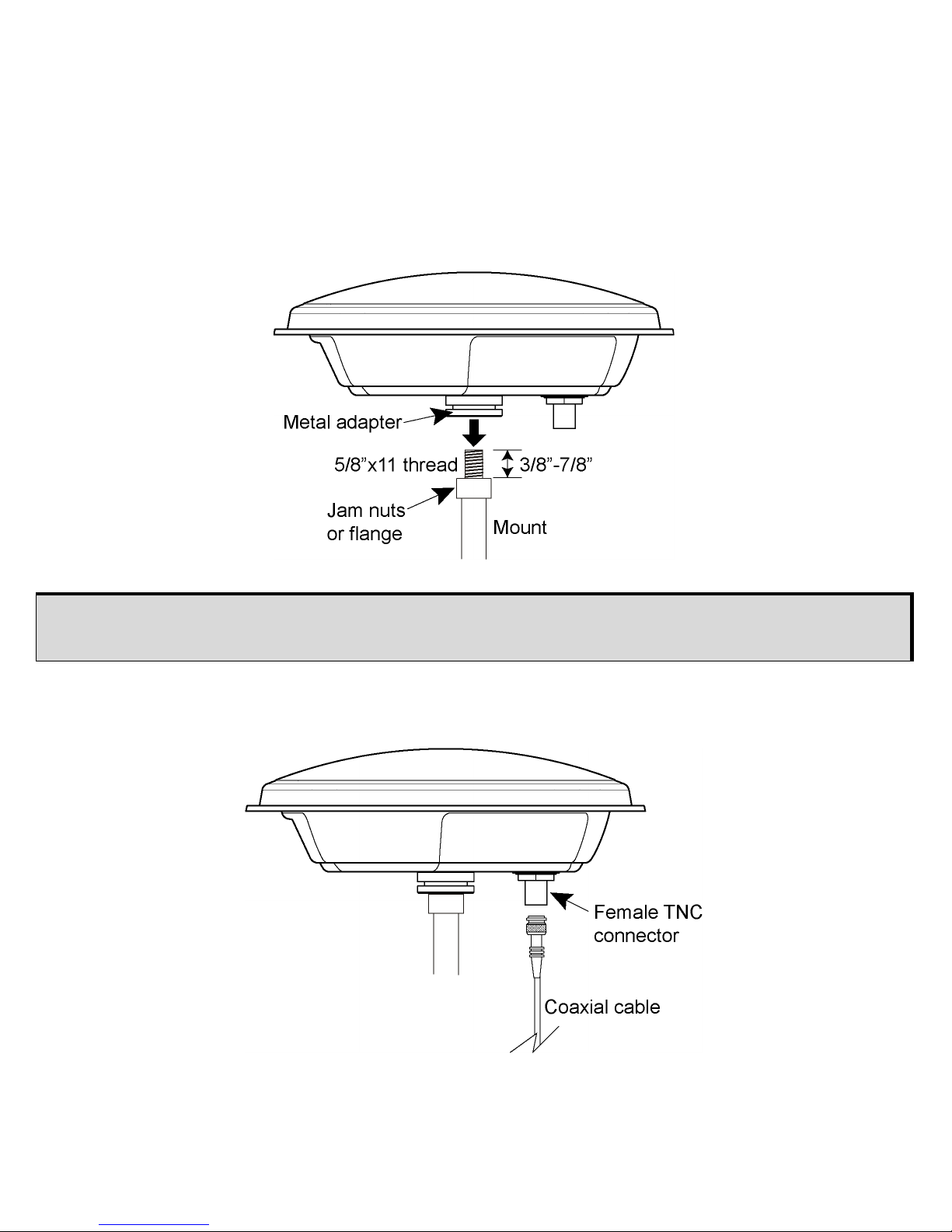
1. Verify that the thread on the mount does not extend more than 7/8" (22 mm) to ensure the plastic
inside the antenna receptacle is not damaged when the mount is inserted. If it extends further than 7/8"
(22 mm), add two jam nuts to shorten the exposed thread, ensuring the nuts are well-tightened.
2. Align the mount thread with the metal adapter on the bottom of the antenna and rotate the antenna
clockwise until it is securely screwed to the mount.
3. Remove the dust cap from the antenna’s connector.
4. Attach the TNC connector of the coaxial cable to the antenna’s TNC connector.
5. Attach the other end of the coaxial cable to the antenna input port of the receiving device.
The receiving device must provide power as detailed in the SPECIFICATIONS section of this guide. All
NovAtel GNSS receivers provide the necessary power through their antenna RF connectors.
The metal adapter on the bottom of the antenna is fixed in place. Do not attempt to remove it.
3
ANTENNA CARE
The GNSS-800 Series are designed to withstand the elements, including rain, snow and dust. However, to
ensure your antenna performs optimally, keep the radome (the top surface of the antenna) clean and brush
off any ice and snow. In addition, ensure the connector remains clean and dry and replace the dust cap
when a cable is not connected.
SPECIFICATIONS
RADIO FREQUENCY
Pass band (typical)
Upper passband: 1568 ± 43.0 MHz
Lower passband: 1232 ± 68.0 MHz
L-Band: 1545 ± 20.0 MHz (802L, 804L and 850
models only)
Out-of-band rejection Band edges ± 50 MHz 40 dB min
Band edges ± 100 MHz 60 dB min
Gain at zenith (90°)+5.0 dBic min
Gain roll-off (zenith to horizon)a
a. Refer to the table Signals Received for model specific signals.
L1 11 dB
L2 12 dB
LNA gain (typical) 29 dB
Polarization Right-Hand Circular
Noise figure (typical) 2.0 dB
L1-L2 differential propagation delay (maximum) 5 ns
Nominal impedance 50
VSWR ≤2.0:1
POWER
Input voltage +3.8 to +18 VDC
Current (typical) 60 mA (maximum)
PHYSICAL
Diameter 176 mm
Weight 507 g (17.9 oz)
ENVIRONMENTAL
Maximum altitude 12,192 m (40,000 ft)
Operating temperature -40°C to +85°C (-40°F to +185° F)
Storage temperature -55°C to +85°C (-67°F to +185°F)
Humidity 95% non-condensing
Random vibration MIL-STD-810G(CH1), 514.7 Annex E Procedure 1, Category 24
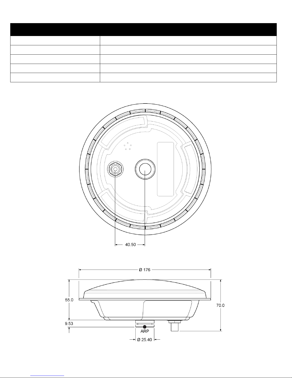
4
MECHANICAL DRAWINGS
Shock MIL-STD-810G(CH1), 516.7 (40 g), Procedure 1
Bump IEC 60068-2-27
Salt fog MIL-STD-810G(CH1), 509.6
Water resistance IP67
Compliance FCC, CE
ENVIRONMENTAL

5
Refer to the Mechanical Drawing and the close-up of the label below before reading this section.
Table 1 shows typical absolute and relative offset numbers for the GNSS-800 series antennas.
Table 1: Phase Center Offset
WEEE
If you purchased a GNSS-800 Series antennas in Europe, return it to your dealer or supplier at the end of
its life. The objectives of the European Community's environment policy are, in particular, to preserve,
protect and improve the quality of the environment, protect human health and utilise natural resources
prudently and rationally. Sustainable development advocates the reduction of wasteful consumption of
natural resources and the prevention of pollution. Waste electrical and electronic equipment (WEEE) is a
regulated area. Where the generation of waste cannot be avoided, it should be reused or recovered for its
material or energy. WEEE products may be recognized by their wheeled bin label ( ).1
ROHS
The GNSS-802, GNSS-802L, GNSS-804, GNSS-804L and GNSS-850 are compliant with the European
Union (EU) Restriction of Hazardous Substances (RoHS) Directive 2011/65/EU.
REACH
The GNSS-802, GNSS-802L, GNSS-804, GNSS-804L and GNSS-850 are in compliance with Regulation
(EC) No 1907/2006 OF THE EUROPEAN PARLIAMENT AND THE COUNCIL of 18 December 2006
concerning the Registration, Evaluation, Authorization and Restriction of Chemicals (REACH). The
Candidate List of Substances of Very High Concern (SVHC) published by the European Chemical Agency
(ECHA) is updated occasionally and available at https://echa.europa.eu/candidate-list-table. Please
contact NovAtel Customer Support if you require further information.
Only integer hardware revisions affect the phase center offsets. For example, the numbers given
for hardware revision 2.02 are applicable to an antenna labeled H/W Rev: 2.00, 2.04 or 2.12.
Absolute Height
L1 60.0 mm
L2 60.0 mm
1. See www.novatel.com/products/compliance/environmental-compliance/ for more information.
Antenna Model
Hardware Revision

6
WARRANTY POLICY
NovAtel Inc. warrants that its Global Navigation Satellite System (GNSS) products are free from defects in
materials and workmanship, subject to the conditions set forth on our web site: www.novatel.com/products/
warranty.
GNSS Antenna™ Modules: One (1) Year
Cables and Accessories: Ninety (90) Days
RETURN INSTRUCTIONS
To return products, refer to the instructions found under the Return Policy Tab on the warranty page:
www.novatel.com/products/warranty.
QUESTIONS OR COMMENTS
If you have any questions or comments regarding your GNSS-800 Series antennas, contact NovAtel
Customer Service using one of methods provided below.
Log a Case and Search Knowledge:
Website: www.novatel.com/support
Log a Case, Search Knowledge and View Your Case History: (login required)
Web Portal: https://novatelsupport.force.com/community/login
Email:
Telephone:
U.S. and Canada: 1-800-NOVATEL (1-800-668-2835)
International: +1-403-295-4900
© Copyright 2017 NovAtel Inc. All rights reserved.
Unpublished rights reserved under international copyright laws.
Recyclable.
Table of contents
Popular Antenna manuals by other brands


Novatel
Novatel GNSS-750 Guide

Amphenol
Amphenol RETU-Ex01 installation guide

California Digital Group
California Digital Group 1292B operating manual

Ubiquiti
Ubiquiti PowerBeam M PBE-M2-400 quick start guide

CommScope
CommScope CMAX-DMF4-43-Wi53 installation guide

Teltonika
Teltonika MAXVIEW MXL050/G Installation & user's instructions


