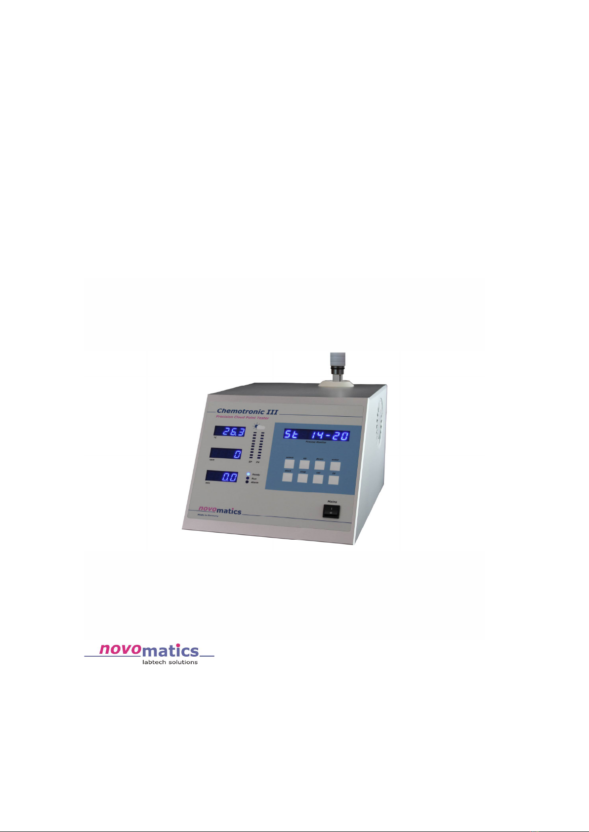
novomatics HEMOTRONIC III User manual
Operation Manual
of CHEMOTRONIC III
Owner's Manual
Issue: 03/2022 (c) by NOVOMATICS GmbH
NOVOMATICS GmbH
Aubachstr. 1
D-56410 Montabaur
Germany
Phone:++(49) 26 02 – 919 9622
FAX: ++(49) 26 02 – 919 8052
solutions@novomatics.com
www.novomatics.com

CHEMOTRONIC III
2
Contents:
1.Safety Precautions ..............................................................................................4
1.1.Safety instructions .......................................................................................4
1.2.Instrument Safety.........................................................................................4
1.3.Calibration...................................................................................................7
2.Operation modes..............................................................................................10
2.1.Change the operation mode..................................................................11
2.2.Change the passcode .............................................................................11
3.Testing printing ink resins..................................................................................12
3.1.Cloud point or mineral oil tolerance (MOT) ..........................................12
3.2.Automatic cloud point test method.......................................................12
3.3.Test oils .......................................................................................................13
4.Features of CHEMOTRONIC III ..........................................................................14
5.Installation..........................................................................................................15
6.Calibration .........................................................................................................16
6.1.Temperature calibration..........................................................................16
6.2.Speed calibration.....................................................................................16
6.3.Time calibration ........................................................................................16
6.4.Program specific calibration...................................................................19
6.5.Automatic turbidity calibration...............................................................19
6.6.External calibration...................................................................................20
6.7.Turbidity calibration standards................................................................20
7.Function test.......................................................................................................22
8.Cloud point measurement procedure............................................................23
9.Principle of automatic controlled measurement...........................................25
9.1.The data menu..........................................................................................34
9.2.The edit menu ...........................................................................................35
9.3.Use the Prn Option....................................................................................39
10.How to create a test parameter set ..............................................................40
11.Warnings, Failure detection and hazards.....................................................42
11.1.Warning....................................................................................................42
11.2.Failure detection.....................................................................................42
11.2.1.PT100 trouble ...................................................................................43
11.2.2.Temperature doesn't increase ......................................................43
11.2.3.Stirring Motor trouble......................................................................43
11.2.4.Cooling Motor trouble....................................................................43
11.3.Hazards ....................................................................................................44
12.Photocell cleaning instructions......................................................................46
12.1.Inspection of photocell operation ........................................................46
12.2.Photocell cleaning procedure..............................................................47

CHEMOTRONIC III
3
13.Failure check-list.............................................................................................48
13.1.Trouble shooting......................................................................................48
14.Operation with impact printer .......................................................................51
15.WinTURBI Software ...........................................................................................52
15.1.Computer Connection of the Chemotronic III ....................................53
Appendix54
Standard test method for cloud point measurements .....................................55
Specification.........................................................................................................58
Spare parts and test materials............................................................................59
Front Side CHEMOTRONIC III..............................................................................61
Rear Side CHEMOTRONIC III................................................................................62
Distributors ...........................................................................................................63

CHEMOTRONIC III
4
1. Safety Precautions
1.1. Safety instructions
Read operation manual before starting to work with the instrument. Make sure,
that every operator fully understands every function of the instrument and each of
its components.
Working with solvents and high temperatures does not need to be dangerous when
all safety recommendations are understood and obeyed by the operator
1.2. Instrument Safety
·When mineral oil is used as a solvent, make sure its boiling point is over the
max. level of the temperature profile of 230°C. If not, decrease this level to
the boiling point of the solvent less 20°C or more.
·Put the magnetic stirring bar gently into the glass test tube, by tilting the
tube.
·In case a glass test tube would break, the instrument must be switched off
immediately. All the solvent in the metal jacket holding the test tube must be
removed, before switching on again.
·Never use a glass test tube twice.
·Wear heat protection gloves when removing a hot test tube or cleaning a hot
temperature sensor tip.
·Do not remove any part from the instrument during operation.
·If you have doubts about safety when a situation occurs that is not
mentioned in the operation manual, contact the manufacturer or its
representative.

CHEMOTRONIC III
5
Before switching on:
-Ensure that the power cable plug is connected to a main socket with an earth
contact.
-Ensure that the temperature sensor is inserted into the test tube and the cable
is connected to CHEMOTRONIC.
- The CHEMOTRONIC has three hot spots during a run:
1. the visible edge of the glass test tube holder
2. the air outlet of the cooling box at the rear
3. the air outlet of the case at the rear
Never touch these and be sure to have a minimal distance to any object of about
10 centimetres
The instrument will automatically heat up the sample in the test tube as fast as
possible (approx. 1°C per sec.). After having reached the top temperature, this
temperature level is hold constant for several minutes (hold time setting) in order
to dissolve all solid particles. Then the sample is cooled down as fast as possible
(approx. 0.5°C per sec.). Turbidity is detected automatically and the cloudpoint
temperature value is printed out via the optional data printer simultaneously.
There are 3 variable rotation speed settings for the magnetic stirring bar:
·n1 during heating up (fastest speed for optimal mixing)
·n2 during hold time and cool down (slow speed to avoid air bubbles)
·n3 below T
3
(< 80°C faster speed for optimal homogeneity)

CHEMOTRONIC III
6
1.2.1. Measuring devices
Temperature measurement: Pt 100 temperature sensor
(100 Ohm resistance thermometer9
Accuracy: ± 0.5°C
Rotation measurement: Digital tachometer on motor shaft.
Magnet stirring bar will follow the
rotational speed during the sample is in
liquid state.
Accuracy: ± 1 rpm
Turbidity measurement: Infrared transmitter and receiver devices
with glass fibre extension leads. The tips
of the glass fibre leads can be cleaned
through the metal test tube holder with
a brush.
Accuracy: ± 10 NTU
(nephelometric turbidity units)
All 3 values are displayed on digital indicators at the front of the instrument, by
which also the setpoints can be adjusted. The min. and max. values of the
turbidity range can be set by individual calibration:
P1: min. turbidity by a transparent sample
P2: max. turbidity by an intransparent sample
(for instance solidified solution)

CHEMOTRONIC III
7
1.3. Calibration
The following turbidity calibrations can be used:
Ac = automatic calibration, applicable to Std-program and user programs U1 –
U8.
Max. sensitivity is a setting at 90 % of the max. clearness of the solution.
Min. sensitivity is a setting at 10 % of the max. clearness of the solution.
Pc = program specific calibration.
As Ac, but max. and min. of the turbidity range must be defined by the
user. For this the calibration function must be used for each individual
program.
Ec = external calibration:
This is a global calibration for all test programs. The turbidity range can be
set by using the calibration function.
Remember:
The factory setting for the calibration mode is Ac, so that there is no need to use a
standard turbidity solution for calibration.

CHEMOTRONIC III
8
1.3.1. Introduction
This chapter is providing information on the basic concept of the cloud point
measurements of resins for applications in printing inks.
In lithography printing conventional oil-based paste inks perform best. These inks
consist of resins, mineral oils, pigments and additives. Therefore the performance
of these inks is highly depending on the compatibility of all these components. In
order to test the compatibility of a resin and a mineral distillate, the resin must be
dissolved in the mineral distillate at a high temperature first. When cooling this
solution, the resin will precipitate in the liquid at a specific temperature, which is
called the cloud point. The cloud point can accurately be detected by automatic
turbidity measurement with the CHEMOTRONIC.
Turbidity is defined as an optical property of a liquid caused by light scattering and
absorption. This state will be caused by unsolved particles, for instance fine
polymers or organic material. These particles solved in a liquid lead to haze or
turbidity, if the light passes through the liquid. Easily said, turbidity is the opposite
of clearness.
In case of a resin dissolved in oil, the precipitation process increases rapidly within
a small temperature interval until full solidification of the varnish. The temperature
at which this happens is the so-called solidification point which is closely related to
the cloud point. Deviations in the cloud point can lead to sedimentation in the
varnish, differences in drying speed, loss of gloss and tack stability of printing inks.
Therefore the cloud point is a characteristic value for the specification of printing
ink resins.
In the past the cloud point detection could be determined on the manual way only.
This test method had many sources of error and uncertainty due to poor
reproducibility, variances in heating and cooling of the sample, inaccurate turbidity
determination, etc.

CHEMOTRONIC III
9
The CHEMOTRONIC determines the cloud point of hard resins in solutions based on
mineral distillates of analytical quality. To determine the cloud point accurately and
reproducibly, the temperature of the test liquid must be cooled down under
reproducible conditions until a reduction of transparency due to the effect of
suspended particles, i. e. turbidity occurs. The cooling rate plays a dominant role in
these local saturation and precipitation processes. However, the transparency
reduction due to colour changes must be eliminated in turbidity measurements. The
observed effect of the liquid on light passing through it will change in case of colour
changes, but the turbidity will not change. Therefore infrared light is generally
chosen for turbidity measurements to reduce the absorption effect caused by
different colours. However, turbidity is not empirical. It depends on the effect of
suspended particles on infrared light passing through the liquid, which in turn
depends on the similarity of the process and the measurement each time.
As the turbidity measurement must be combined with the temperature
measurement, a special infrared-photocell-system has been designed for the
CHEMOTRONIC.
This fibreglass infrared-photocell-system measures the absorption of the infrared
light beam passing through the glass test tube. The spectral response of the silicon
photo diodes shows a max. sensitivity at approx. 950 nm, which is well beyond the
region of visible light (380 - 780 nm), so that effect of visible colour changes is
eliminated generally. This makes the photocell more sensitive for low turbidity
measurements.
The output signal of the photocell detection circuit decreases linear with increasing
turbidity within the relevant turbidity range. The user can adjust which turbidity
point is recognized as the cloud point by executing a calibration procedure and
choosing one of ten turbidity levels.
The fibreglass infrared-photocell-system for turbidity measurement in the
CHEMOTRONIC III has proven to be a rugged and reliable device, designed for
continuous use in factory environment, if the tips of the fibreglass are kept clean.

CHEMOTRONIC III
10
2. Operation modes
In accordance with the practical requirements of modern quality managment
systems two operation modes were implemented into the instrument. The first
mode called Prod-Mode includes a limited function set only and is intended for the
quality control generally. The second mode called Lab Mode allows the access to
the complete function set and is intended for the laboratory control or to adjust the
Prod Mode.
After switching on the actual mode is displayed in temperature display fot two
seconds. The following table gives an overview about each function set:
Prod mode Lab mode
program choose no
(standard prog)
yes
run a measurement yes yes
check the last 20
measurement data
yes yes
editing user programs no yes
set time and date no yes
turbidity calibration no yes
LAB-mode:
This mode is providing free entry to all functions without any limitation. One can set
the temperature profiles, rotation speeds and turbidity levels according to the
individual demands. Up to 8 menus can be stored and retrieved so that these can
be used for particular samples that need different parameters.

CHEMOTRONIC III
11
Prod-mode:
This mode is meant for production control applications of the CHEMOTRONIC. In the
quality assurance mode, only 1 standard is active and can be started. The upper
row of push buttons on the front panel is inactive in this mode.
2.1. Change the operation mode
1) Press Sel button twice for entering into edit menu
2) Press up/down button till the actual mode OP Lab or OP Prod is blinking.
3) Press enter button for enabling mode change
4) Press up/down button for mode change and acknowledge by enter button
5) Now passcode is needed. Enter passcode by setting digit by digit, use
up/down buttons for digit setting and enter button for going to next digit,
the first passcode after leaving factory is 444444
6) After successful setting the buzzer sounds shortly
2.2. Change the passcode
The operation is save only with unknown passcode. That’s why the passcode should
changes at next supervisor’s opportunity. Please note that passcode can be
changed only when the instrument is in the Lab mode.
1) Press Sel button twice for entering into edit menu
2) Press up/down buttons till the word code is shown.
3) Press the enter button, co000000 is shown and the first 0is blinking now
4) Enter actual passcode by setting digit by digit, use up/down buttons for
digit setting and enter button for going to next digit, the first passcode
after leaving factory is 444444
5) When accepted cn000000 is shown and the first 0is blinking now
6) Enter new passcode by setting digit by digit, use up/down buttons for digit
setting and enter button for going to next digit
7) When successfully entered the buzzer sounds shortly and the new passcode
is blinking for 2 sec.

CHEMOTRONIC III
12
3. Testing printing ink resins
Statistically, specifications of raw materials can at best be only as consistent as the
test procedures used to determine them. Test procedures should be based on
scientifically
approved principles, which means accurate test equipment for controlled test condi-
tions such as heating and cooling temperature profiles, top temperature dwell time,
agitation speed, turbidity determination, etc.
Moreover the test oil in which the resin is dissolved must have analytical quality.
3.1. Cloud point or mineral oil tolerance (MOT)
Some product specifications have been based on the MOT-value (mineral oil toler-
ance) in the past. The MOT-value is calculated from the ratio in weight when a hard
resin dissolved in a mixture of mineral distillates is titrated with mineral distillate
until the solution becomes cloudy. This method is relatively inaccurate and depends
strongly on the temperature of the solution way of stirring, observation of
precipitation and the experience of the person performing this test.
3.2. Automatic cloud point test method
The cloud point temperature is a characteristic value resins for printing inks.
Deviations in cloud point can lead to sedimentation in the varnish, differences in
drying speed, loss of gloss and tack stability.
The cloud point is the temperature at which a resin begins to precipitate in the
liquid phase. The automatic cloud point test method introduced here, has been
approved by a great number of resin manufacturers world-wide as a standard
method for production setting and quality control of resins for printing inks.

CHEMOTRONIC III
13
3.3. Test oils
Resins used in printing inks today differ considerably in solubility and mineral oil
tolerance. Therefore resins are tested in the liquid phase and subsequently the
properties of the solution is also depending on the solvency of the test oil.
Therefore a test oil must be made by appropriate processing of carefully selected
oils in order to achieve a product of consistent analytical quality so that solvency
deviations do not effect the measurements.
As test oils of different solvency are necessary to test various types of resins, the
standard test method is based on the usage of test oils with different aromatics
content. The following test oils are analytical grade test oils with the same
properties as the industrial grade oils used for varnishes (manufacturer: ASCOT
HALTERMANN):
- Test oil PKWF 6/9 (approx. 20 % aromatics) = high solvency
- Test oil PKWF 6/9 AF (< 1 % aromatics) = low solvency
- Test oil PKWF 6/9 AF new (< 1 % aromatics) = medium solvency
Test procedure:
A quantity of 2.0 grams of resin with 18.0 grams of test oil are precisely weighed
into a glass test tube with a magnet stirring rod. This test tube is placed into the
automatic cloud point tester CHEMOTRONIC. Under determined heating and stirring
conditions the mixture is heated up to 230°C and remains at this temperature level
for 2 minutes during which the resin is completely dissolved. After this time, an
infrared photocell is activated for automatic turbidity detection at a calibrated level
during the falling slope of the sample temperature.
The cloud point is determined at the temperature at which the resin precipitates in
the solution. The test result is subsequently printed out by the optional data
printer.

CHEMOTRONIC III
14
4. Features of CHEMOTRONIC III
The CHEMOTRONIC III is a fully automatic turbidity measuring unit for the
determination of the cloud point of hard resins. The main features of the
CHEMOTRONIC III are :
- Reproducible cloud point detection and documentation via optional impact
printer or WinTURBI PC software
- Automatic microprocessor controlled test system for production and quality
control applications in industrial production processes of printing inks
- Time-saving, fully automatic test method, independent on the analyst or
circumstances
- Accurate, reliable and easy to operate precision test system as well for
laboratory use as for the production of printing inks
- Cost savings by higher production yields, improved final ink product quality
and less labour costs
- Different temperature profiles predefined by factory or user
- Fast calibration procedure to define the turbidity detection range by user
- User definable stirring speed control to reduce the generation of bubbles
and to improve the accuracy
- Complete remote control via USB by PC with the software package
WinTurbi V2.0
- Measurement result overview and comparison with date, time and
comments of the last 20 measurements by the software package WinTurbi
V2.0 or printing via optional impact printer
- Easy to use by "switching on and pressing start" for a high measurement
efficiency
- Implementation of security algorithm for a fast failure detection and to
improve the device safety

CHEMOTRONIC III
15
5. Installation
The CHEMOTRONIC III is an automatic test instrument for table top use. It includes
all required mechanic and electronic components and requires no installation
experience.
When the CHEMOTRONIC III is put into operation the following two must be made:
1. The main cable for power supply. The standard operating voltage is 230 V ±
10 % / 50 – 60 Hz. In case of 100 – 125 V mains voltage, an optional
transformer is needed to increase the mains voltage to the standard operating
voltage of the instrument. Please note, always an earth connection is
available at the wall socket.
2. The Pt 100 temperature sensor with cable, protected by a spiralized metal
sheath, and a five pole screw type plug must be connected to the instrument.
The Pt 100 input socket is located at the rear side. Please note, there is a slot
in the input socket in which the nose of the plug has to fit. Place the plug on
the socket in the correct position first, before turning the knurled metal collar
of the plug clockwise in order to insert the plug into the socket. Do not use a
lot of force and do not try to connect the plug in an incorrect position.
This may destroy the fine gold-plated pins of the socket, so that the instrument
will need to be repaired not under guarantee.
To ensure a save operation of the device the user has to be sure to have a minimal
distance 25 of centimetres to any object at the rear side. When the connections
have been made, the equipment can be switched on by pressing the power push
button at the right side of front panel. If the self test proceeds without any failure
the led of the start/stop button is illuminating after two seconds.

CHEMOTRONIC III
16
6. Calibration
6.1. Temperature calibration
In the Chemotronic a powerful microprocessor system is installed for the control of
all instrument functions. A 12 bit A/D-converter is used to convert the analogue
inputs of the Pt 100 sensor into a digital signal. The input circuit is designed for
automatic zero setting (auto zero) and automatic span setting (auto cal) by internal
references. Therefore manually calibration of the temperature measuring functions
is eliminated.
The temperature control functions are also automatically optimised for quick
temperature response and control (self tune). Therefore , manual settings of
control parameters are eliminated is well.
6.2. Speed calibration
The speed of the magnetic stirring rod in the test tube is controlled by a motor with
tachometer and electronic drive circuit. Therefore rotation speed settings and
indications are absolutely exact. As the motor speed is controlled, the speed
indication is also indicating a rotation speed when the magnet stirring rod is in a
fixed position in the test tube, for instance due to molten resin in the test tube.
6.3. Time calibration
Due to the high accuracy of the built in real time clock there will be no short term
deviations in the timing functions.
CHEMOTRONIC III
17
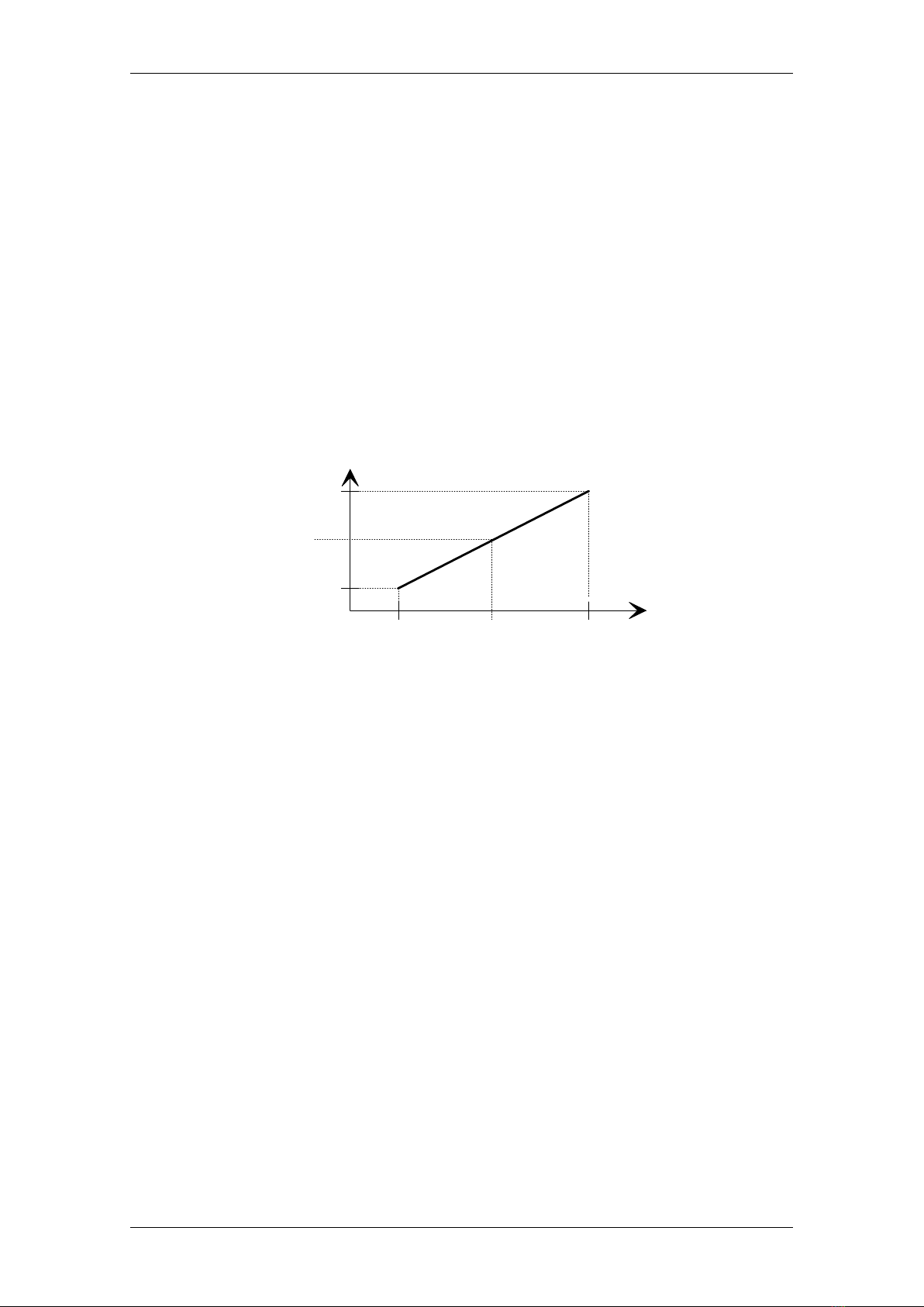
6.3.1. Turbidity calibration
The software controlled infrared photo cell system offers two functions to calibrate
the system and to determinate the cloud point reference. The user can adjust
which turbidity point is recognized as the cloud point by executing a calibration
procedure and choosing one of ten turbidity levels to fix the sensitivity within the
range. The output signal of the detection circuit decreases linear with increasing
turbidity within the relevant turbidity range. The following picture shows the
relation:
Turbidity
Level
P1 P2
1
10
absolute light
absorption
Setpoint
(for instance "5")
Fig.: 6.1
The absorption points P1 and P2 are determined by two calibration liquids, for in-
stance water or test oil and diluted FORMAZIN. The turbidity within P1 and P2 is
linear imaged to the turbidity levels between 1 and 10. During the measurement
the user definable setpoint is compared to the sample continuously, until the light
absorption exceeds this point turbidity is detected. If no measurement is running it
is very simple to check the calibrated defined turbidity range. By inserting one after
another of two test tubes with different calibration liquids the turbidity scale should
display level "0" and level "10".

CHEMOTRONIC III
18
The turbidity measurement in the CHEMOTRONIC is performed by an infrared-
photocell system taking both absorption and scattering infrared light passing
through the sample under test into account. The measuring circuit is designed for
full range measurements both of samples with a low turbidity and of samples with a
high turbidity. In order to achieve a high resolution, the setpoint value can be set in
10 different steps from min. turbidity (P1) and max. turbidity (P2). These turbidity
levels can accurately be calibrated by the following calibration procedure:
1) Press the cal button and wait until the auto cal-functions have been
checked and the system is ready to accept the min. turbidity value.
The display is showing "Cal P1".
2) Insert a clean test tube filled with water or mineral distillate in the
CHEMOTRONIC and press the enter button (¿). The display is
showing "Cal P2" now.
3) Insert a test tube filled with the prepared FORMAZIN turbidity
calibration standard in the CHEMOTRONIC and press the enter
button again. Both the min. and max. value of the turbidity scale are
stored in the memory after this procedure.
Note: 1) The sequence can be P1/P2 or P2/P1. In both cases the correct
values are stored for correct turbidity calibration
2) The Chemotronic is factory calibrated for a period of at last 12
month after delivery. See also Turbidity calibration standards.
3) Formazin is a turbidity standard liquid (see 6.5)

CHEMOTRONIC III
19
Test tube filled with
transparent sample
(water or minerale destillate)
Cal P1
Test tube filled with
intransparent sample
(Formazin solution)
Cal P2
6.4. Program specific calibration
This additionally feature allows the user to use an individual turbidity range for the
current measurement program. This option can be selected by choosing Pc at the
end of the parameter list. By depressing of the cal button within this menu the
calibration menu appears and it is possible to calibrate the both points P1 and P2
now.
6.5. Automatic turbidity calibration
Every program can have its individual turbidity calibration, if one select Ac at the
end of the parameter list. In this case an automatic calibration is carried out when
the photocell is activated (T1- 20 °C = T2). At high temperature, the test solution
is still clear, so that the turbidity is at a minimum level. This level is automatically
stored as turbidity level P1(min. range).
In addition to this, a factor can be set for automatic turbidity detection when the
solution becomes hazy. The factor is set as a percentage of clearness of the

CHEMOTRONIC III
20
solution measured by the automatic calibration procedure. The factor can be varied
between 90 % (clear) and 10 % (hazy).
This adjustment is particularly of interest for solutions which show a slight turbidity
only or those with a turbidity range. The standard test program is adjusted for
automatic calibration, as it eliminates the necessity of turbidity standards. The
setting of P
2
= 20 % of P
1
(Ac20).
6.6. External calibration
Ec is a global calibration for all test programs by means of turbidity standards. Both
P
1
and P
2
must be calibrated by standard solutions, valid for all test programs.
6.7. Turbidity calibration standards
In turbidity measurements, primary turbidity standards are required as these are
the only certified standards. By diluting a primary turbidity standard a secondary
standard can be made for actual use. The derived turbidity value is traceable to the
original primary standard. It is accepted that dilutions are less stable and cannot be
used over a longer period of time (max. 1 week). The definition of turbidity units is
based on the polymer suspension FORMAZIN. A FORMAZIN primary turbidity
standard is specified for 4000 Nephelometric Turbidity Units (NTU). A wide range of
secondary standards can be made by dilution with distillated water (see calibration
procedure). A 4000 NTU turbidity standard is stable for long period of time (max. 1
year). Titration of FORMAZIN has proven to be the fastest and most convenient
means of an accurately working turbidity standard.
Table of contents
Other novomatics Measuring Instrument manuals


Popular Measuring Instrument manuals by other brands


Hubner
Hubner Cobolt Tor Series owner's manual

Veto
Veto DF68D user guide

Endress+Hauser
Endress+Hauser Gammapilot FMG50 operating instructions

National Instruments
National Instruments NI 5731 Series USER GUIDE AND SPECIFICATIONS

TANEL Electronics
TANEL Electronics WIP-22D user manual

EMIS
EMIS EMIS-VIHR 200 Operation manual


