Sensitron GAS-PRO User manual

GASPRO
SENSITRON
A Halma Company
GAS-PRO
Manual
M07995
SENSITRON S.R.L. - All rights reserved - www. sensitron.it
Multi-gas monitor
Manual
M07995 - Issue 14 July 2020
Sensitron S.r.l., Viale della Repubblica 48, Cornaredo (MI)
TEL. +390293548155 FAX. +390293548089

SENSITRON
A Halma Company
M07995
GAS-PRO
Manual (EN)
P. 2/47
P. 5 Prologue
P. 5 Gas-Pro Overview
P. 5 Safety Information
P. 8 Unpacking
P. 8 1. Set-up
P. 8 1.1 Prior to use
P. 8 1.2 Gas-Pro orientation
P. 8 1.3 Charging
P. 9 1.4 Fitting a flow plate
P. 10 1.5 Quick view
P. 11 2. Operation
P. 11 2.1 General
P. 11 2.2 Turn on
P. 11 2.3 Pump test
P. 14 2.4 Detecting gas
P. 15 2.4.1 Diusion monitoring
P. 15 2.4.2 Pumped mode
P. 15 2.4.3 Manual sampling
P. 16 2.4.3.1 Using the Hand Aspirator
P. 17 2.5 Alarms
P. 17 2.5.1 Low battery alarm
P. 17 2.5.2 Instantaneous alarm
P. 17 2.5.3 Time weighted average alarm (TWA)
P. 18 2.5.3.1 TWA Resume function
P. 18 2.5.4 Accepting and clearing alarms
P. 19 2.5.5 Sensor types
P. 19 2.5.5.1 Oxygen sensors
P. 19 2.5.5.2 Electro-chemical sensors
P. 20 2.5.5.3 Infra red sensors
P. 20 2.5.5.4 Pellistor sensors
P. 20 2.5.5.5 Pellistor saver mode
P. 20 2.5.5.6 PID
P. 20 2.6 Gas-Pro functions
P. 21 2.6.1 Accessing the user menus
P. 21 2.6.2 Home screen
P. 21 2.6.3 Manual zero
P. 22 2.6.4 Time weighted average
P. 22 2.6.5 Pre-entry check (PEC)
P. 22 2.6.5.1 Starting a Pre-entry check
P. 23 2.6.5.2 Carrying out a Pre-entry check
P. 24 2.6.6 Peak review
P. 25 2.6.7 Pellistor Correction Factor
P. 25 2.6.8 Settings
P. 25 2.6.8.1 User setting
P. 25 2.6.8.2 Pump setting
P. 25 2.6.8.3 Sounder volume
P. 26 2.7 Shut down
P. 26 2.8 Additional Features
P. 26 2.8.1 +ve Safety™
P. 26 2.8.1.1 +ve Safety™ indicator meanings

SENSITRON
A Halma Company
M07995
GAS-PRO
Manual (EN)
P. 3/47
P. 26 2.8.2 Data and event logging
P. 27 2.8.3 Bump/Pump functionality
P. 27 2.9 Tank Check Mode
P. 27 2.9.1 Dual-Range Operation
P. 29 2.9.2 Dierences with Home Screen
P. 29 2.9.2.1 Instantaneous Alarms
P. 29 2.9.2.2 TWA
P. 29 2.9.2.3 Pre-Entry Check (PEC)
P. 29 2.9.2.4 Confidence Tone
P. 29 2.9.2.5 Display Backlight
P. 29 3. Gas testing and calibration
P. 30 3.1 Introduction
P. 30 3.2 Bump Test Functionality
P. 31 3.2.1 Speedy bump
P. 31 3.2.1.1 Procedure
P. 31 3.2.2 Smart bump
P. 32 3.2.2.1 Procedure
P. 32 3.2.3 Calibration after bump fail
P. 32 3.2.3.1 Procedure
P. 33 3.2.4 New sensor calibration/service
P. 33 3.3 Gas test screen flow
P. 34 4. Icon overview
P. 35 5. Service and maintenance
P. 35 6. PC interface and Portables Pro
P. 35 6.1 General
P. 35 6.2 PC interface cable
P. 36 7. Accessories
P. 36 8. Specification
P. 38 9. Troubleshooting
P. 39 9.1 Pump test failure
P. 39 9.2 Fault screens
P. 39 9.2.1 Fault Descriptions
P. 40 9.2.2 Fault codes
P. 41 10. Appendices
P. 42 10.1 Sensors
P. 42 10.1.1 Toxic
P. 42 10.1.2 Flammable Pellistor Sensors
P. 42 10.1.3 Flammable IR Sensors
P. 42 10.1.4 Oxygen
P. 43 10.1.5 IR
P. 43 10.1.6 PID
P. 43 10.2 Sensor Limitations

SENSITRON
A Halma Company
M07995
GAS-PRO
Manual (EN)
P. 4/47
P. 44 10.3 Charging and run times
P. 44 10.4 Contacts
P. 45 Warranty

SENSITRON
A Halma Company
M07995
GAS-PRO
Manual (EN)
P. 5/47
Prologue
Safety Information
GASPRO OVERVIEW
Thank you for purchasing the new Gas-Pro. At Crowcon we recognise the need
for reliable and robust personal monitors which are sized to be worn and simple
to use.
Gas-Pro is a portable monitor capable of detecting up to 5 gases in a compact
and wearable design featuring an optional internal pump. Focused on users and
fleet managers alike, Gas-Pro oers application focused solutions giving greater
operating time and reduced set up time.
Gas-Pro is classified for use in hazardous areas and gives loud and bright audi-
ble and visual alarm indications as well as a vibrate alert. The top mount display
is backlit for ease of use, and the simple single button solution makes using and
training quick and easy.
- Gas-Pro is a hazardous area certified gas detector and as
such must be operated and maintained in strict accord-
ance with the instructions, warnings and label information
included in the manual. Gas-Pro must be operated within
the limitations stated.
- Read and understand all instructions in the operation sec-
tion of the manual prior to use.
- Before use ensure that the equipment is in good condition,
the enclosure is intact has not been damaged in any way.
- If there is any damage to the equipment do not use, contact
your local oce or agent for repair/replacement.
- Do not disassemble or substitute components as this may
impair intrinsic safety and invalidate safety certification.
- Only genuine replacement parts must be used; substitute
components may invalidate certification and warranty of
the Gas-Pro and accessories, reference “Service and Main-
tenance” section of the manual for details.
- No live maintenance is permissible.
- Observe all warnings and instructions marked on the unit
and within the manual.
- Observe site health and safety procedures for gases being
monitored and evacuation procedures.
- Understand the screen display and alarm warnings prior
to use.
- If this product is not working properly, read the trouble-
shooting guide and/or contact your local oce or agent, for
details reference the ‘Contacts’ section of the manual.

SENSITRON
A Halma Company
M07995
GAS-PRO
Manual (EN)
P. 6/47
- Ensure maintenance, service and calibration is carried out
in accordance with the procedures in the manual and only
by trained personnel.
- Gas-Pro must not be charged or have communication to
the device, at ambient temperatures outside of the temper-
ature range 0°C to 40°C.
- Only connect to Gas-Pro in a safe area for charging or
communications.
- Charging cable assemblies, whilst nominally providing a
voltage of 6.5V, must not exceed a voltage of 9.1V as this
may impair intrinsic safety and invalidate safety certification
(Um=9.1V).
- Communication cable assemblies, whilst nominally oper-
ating at a voltage of 3.0V TTL, must not exceed a voltage of
9.1V as this may impair intrinsic safety and invalidate safety
certification (Um=9.1V).
- The devices are intended for use in normal atmospheric
conditions of temperature –20 °C to +55 °C; pressure 80
kPa (0,8 bar) to 110 kPa (1,1 bar); and air with normal oxygen
content, typically 21 % v/v (volume/volume).
- Gas-Pro may be used in Zones 1 and 2, for Group llA, llB
and llC gases and vapours and for Temperature Classes T1,
T2, T3 and T4. (See Certification labels below).
Certification labels
The certification marking is as follows:
- Gas-Pro is certified for use in ambient temperatures in the
range -20°C to +55°C (-4 to 131°F).
- Applicable Standards
Refer to equipment marking for confirmation of applicable
certification before use.
UL CERTIFICATION LABEL ATEX/IECEX CERTIFICATION LABEL MED CERTIFICATION LABEL

SENSITRON
A Halma Company
M07995
GAS-PRO
Manual (EN)
P. 7/47
IECEx
IEC 60079-0: 2013, 6th Edition
Explosive atmospheres – Part 0:
Equipment – General requirements
IEC 60079-1:2014 7th Edition
Explosive atmospheres – Part 1:
Equipment protection by flameproof enclosures “d”
IEC 60079-11: 2012, 6th Edition
Explosive atmospheres – Part 11:
Equipment protection by intrinsic safety “i”
Ex db ia IIC T4 Gb Tamb -20°C to +55°C
IECEx ULD 11.0004X
ATEX
EN 60079-0: 2012 + A11: 2013
Explosive atmospheres – Part 0:
Equipment – General requirements
EN 60079-1:2014
Explosive atmospheres – Part 1:
Equipment protection by flameproof enclosures “d”
EN 60079-11: 2012
Explosive atmospheres – Part 11:
Equipment protection by intrinsic safety “i”
II 2 G Ex db ia IIC T4 Gb Tamb -20°C to +55°C
DEMKO 11 ATEX 1031772X
UL
Gas detector use in hazardous locations Class 1 Division 1, Groups A, B, C and D
only as to intrinsic safety.
UL 913 Applicable Edition of the UL standard
UL60079-0 Applicable Edition of the UL standard
UL60079-11 Applicable Edition of the UL standard

SENSITRON
A Halma Company
M07995
GAS-PRO
Manual (EN)
P. 8/47
Remove the Gas-Pro from the packaging. The standard accessories are under
the supporting trays. The following items will be included as standard:
Box contents
- Gas-Pro
- Quick Start Guide
- Calibration report
The following items are optional:
Optional items
- Charger cradle
- Charger lead (see Power & Communication Cables
Technical Data)
- Flow plate (standard for pumped units)
If you have ordered a charger and/or cradle this will also be
included in the box. Further accessories are available but
will not be contained in the box (see Section 7).
Gas-Pro in the off state can be left on charge indefinitely
Should the unit be deep discharged, the charging indica-
tion will not be shown until the unit has been charging for 1
hour and the operator button has been pressed.
When on and charging a warning will advise the user to turn
the Gas-Pro off after 12 hours or remove from charge.
Store the battery in a full state and recharge at least once
every 3 months.
. PRIOR TO USE
Before use, the Gas-Pro should always be checked for any signs of physical
damage.
Gas-Pro uses a Lithium Ion (Li-ion) battery pack and should arrive with sucient
charge to be used straight out the box. However, if this is the first time of use, you
may need to charge the battery to attain the full operating time (see Charging).
For battery run times, see the table on section 10.3.
The actual operating time will depend on the types of sen-
sor installed.
. GASPRO ORIENTATION
Unpacking
1. Set-up
1. D-ring 4. Sounder 7. Sensor apertures 10. Charging cable
2. Alarm bars 5. Operator button 8. Dual colour LCD display 11. Certification label
3. +ve Safety™ indicator 6. Pump inlet/outlet* 9. Alligator clip

SENSITRON
A Halma Company
M07995
GAS-PRO
Manual (EN)
P. 9/47
. CHARGING
Charging should only take place in non-hazardous (safe) areas. To charge, sim-
ply plug the cable into the charging socket on the Gas-Pro and turn on the
mains supply (see Figure 2 below). If a charging cradle or vehicle cradle is being
used, ensure the Gas-Pro fits firmly on to the power connector.
The charger must be able to supply 6.5V@ 450mA with an
output voltage that does not exceed 9.1V (Um).
When o, to show the Gas-Pro is charging, both LEDs within the alarm bars will
flash red and will change to green once fully charged. This state will contin-
ue until the trickle charge is complete. Charging will then terminate showing no
indication. The screen will also show the battery icon filling in the middle of the
screen when the Gas-Pro is o, and in the bottom left-hand corner when it is on.
The battery icon contains a maximum of six segments to indicate the battery’s
state of charge. For example, with three segments shown and a fourth flash-
ing, the battery is 50% charged , and when all six are shown, the battery is fully
charged (see Figure 3 below).
1
2
3
4
578
10
11
9
6
* Blanked for non-pumped unit.
Figure 2:
Charger connection
Figure 3:
Charging indications
Figure 1:
Gas-Pro
1
1 2
2
SENSITRON
A Halma Company
M07995
GAS-PRO
Manual (EN)
P. 10/47
. FITTING A FLOW PLATE
A flow plate can be used for a number of applications including pumped opera-
tion (remote sampling), manual gas test/calibration or for manual sampling. If the
pumped flow plate is attached before turning the Gas-Pro on and the Gas-Pro
includes a pump, a pump test will commence as part of the start up process (see
Pump test).
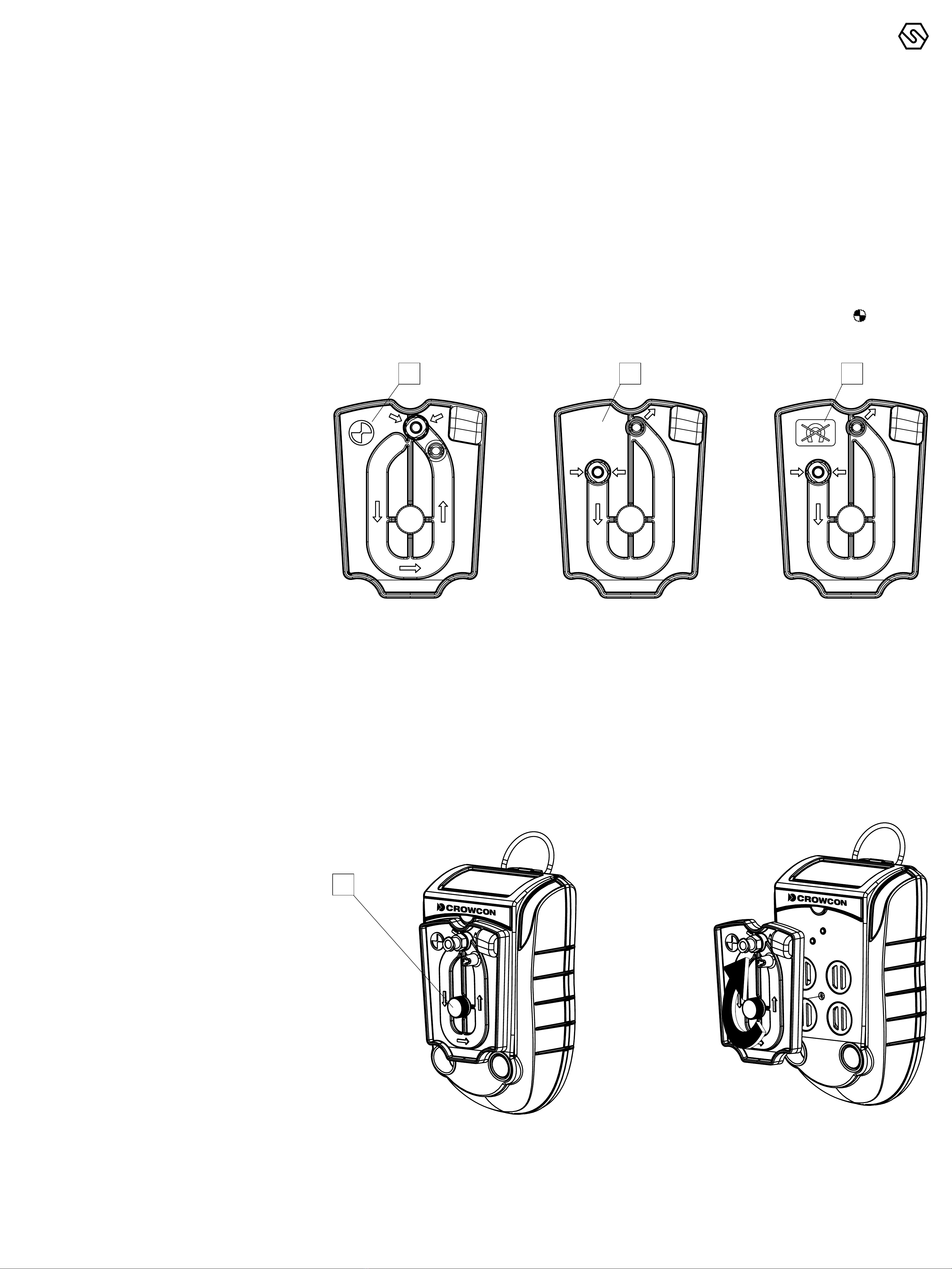
There are 3 types of flow plate: one for a Gas-Pro with internal pump, one for a
Gas-Pro with no pump and a non-magnetic version for PC calibration or for ma-
nual sampling. Although there is no dierence to the attachment procedure, they
are not interchangeable (see Figure 4). The pumped flow plate has the symbol
in the top left corner to aid recognition.
Pumped flow plate
Non pumped flow plate
PC Cal/Test Flow Plate
Check the flow plate’s gasket is free from dirt and has not been damaged prior
to fitting. To fit a flow plate, locate it over the Gas-Pro sensors as shown in Figure
5 and tighten the securing screw .
The flow plate includes a quick connect fitting for attaching sample tubes and
probes.
1 2 3
Figure 4:
Pumped and non pumped flow plates
Figure 5:
Fitting a flow plate
1

SENSITRON
A Halma Company
M07995
GAS-PRO
Manual (EN)
P. 11/47
. QUICK VIEW
Even when the detector is o, users can display details about the configuration
of the Gas-Pro by momentarily pressing the operator button for one audible blip.
The LED to the left of the display will flash red once and the Quick view screen
shown in Figure 6 below will be displayed for 10 seconds.
Gas type and unit detected
Battery status
Quickview icon
ID or serial number
The +ve Safety™ LED status is also shown (see Figure 1).
. GENERALITÀ
Before turning the Gas-Pro on, ensure it is in ‘clean air’
(i.e. outside, in normal air, away from any plant process or
suspected gas location). This will allow the Gas-Pro to be
zeroed using clean air as the base point. If the Gas-Pro is
zeroed in contaminated air a false gas reading can result,
or the zero could fail.
. TURN ON
In ‘clean air’, turn on the Gas-Pro by holding down the operator button for 3 audi-
ble blips. The Gas-Pro will warm up, going through a series of automatic proces-
ses as follows:
Firstly a test screen pattern will be generated. Watch this to ensure there are no
missing pixels on your display screen.
Whilst the Gas-Pro is warming up, two screens will be displayed.
2
4
3
1
Figure 6:
Quick view display
Figure 7:
Initial screens at turn on
2. Operation

SENSITRON
A Halma Company
M07995
GAS-PRO
Manual (EN)
P. 12/47
After a successful test cycle the LCD screen will remain green, the sounder and
LEDs will indicate the Gas-Pro is healthy.
A Gas-Pro fitted with a pump is configured as standard to
start the pump automatically when switched on, provided
that a flow plate is fitted. Such a Gas-Pro tests the pump
automatically at this point (for more details on this, see
Pump test).
If the battery level is low, an alarm will sound, and the bat-
tery icon on the screen will be partial.
If a second ‘splash’ screen has been configured via Por-
tables Pro it will be shown next in the turn on sequence.
If the Gas-Pro is configured for regular Gas Testing (Bump Test), the date of the
last Gas Test will also be shown (for more information on Gas Testing, see Gas
testing and calibration).
The next screen indicates when the Gas-Pro was last calibrated. It also indicates
when the next calibration is due with a warning symbol next to the number of
days left, if this is fewer than 30 days. If the calibration due date has expired, the
number of days figure is not displayed and the warning symbol flashes.
If the calibration due lockout feature has been enabled the lockout icon will
be displayed and the Gas-Pro will not proceed past this point.
Figure 8:
Gas test due screen
Figure 9:
Calibration due screen

SENSITRON
A Halma Company
M07995
GAS-PRO
Manual (EN)
P. 13/47
The next screen (Figure 10) will display the current detector settings (for more in-
formation on these settings, see Gas-Pro functions).
The Autozero Confirm screen will be displayed next.
An Autozero should not be performed unless the Gas-Pro is in clean air. Press
the operator button to enter the Autozero mode, otherwise the countdown will
progress and will not perform a zero.
If the operator button is not pressed the countdown will complete and this fun-
ction will be skipped.
When the autozero has finished or been skipped, the next screen is the home
screen (Figure 12) and displays the gas levels.
The next screen on the Gas-Pro TK edition of Gas-Pro is the Tank Check scre-
en. See the Tank Check Mode section (see Section 2.9) for more information.
Figure 12 shown below is for 5 gases in clean air.
Figure 10:
Current settings screen
Figure 11:
Autozero confirm screen
Figure 12:
Home screen
21
3
4
5
6

SENSITRON
A Halma Company
M07995
GAS-PRO
Manual (EN)
P. 14/47
Gas type
Unit
Level
Home Screen icon
Battery level
Pump present (rotating when on)
In ‘clean air’, CO2 and Oxygen levels are typically 0.04% and 20.9% respectively.
In zero mode, these gases will actually run an ‘oset’ zero.
The Gas-Pro is now ready for use.
EN60079-29 part 1 has been harmonised under the ATEX
directive (2014/34/EU). Therefore to comply with the ATEX
directive, portable apparatus sensing flammable gases
should have a functional check with flammable gas before
each day of use (see Gas testing and calibration). Other
testing regimes may be employed depending on local cir-
cumstances.
. PUMP TEST
In the default configuration, a pumped Gas-Pro with a flow plate attached (see
Fitting a flow plate) will run a pump test during the start up process. A pump test
will also be run whenever a flow plate is attached during normal operation.
If the Gas-Pro is configured for Bump functionality, the
Bump/Pump prompt will be displayed if a flow plate is at-
tached and a gas bump test is due or the Gas-Pro is placed
in a Q-Test module during normal use (see Bump/Pump
functionality).
Prior to fitting, the flow plate’s gasket should be checked for
any damage.
The pump test ensures accurate sealing as well as monitoring pump perfor-
mance. The user will need to cover the pump inlet À (see Figure 13 below) when
prompted to do so by the symbol on the screen.
When the test has finished, the pump will either pass or fail .
If the pump test takes place during start-up and the Gas-Pro passes, the pump
will remain on and the start-up process will continue as normal. If the test is
1
Figure 13:
Pump inlet

SENSITRON
A Halma Company
M07995
GAS-PRO
Manual (EN)
P. 15/47
passed during normal use, the Gas-Pro will remain in the pumped mode until the
flow plate is removed.
On failing the pump test the fail screen will persist with an audible alert until the
button is pressed and the test repeats OR the flow plate is removed and the
Gas-Pro returns to non-pumped operation. For further detail on failing a pump
test see Pump test failure.
. DETECTING GAS
When sampling an area that may contain water, use the ball float probe to re-
duce the potential for water travelling up the sample line.
.. DIFFUSION MONITORING
If you wish to monitor gases in ambient air for dangerous levels, the Gas-Pro
can be worn by either clipping the strong alligator clip to clothing/overalls in the
breathing zone or through the use of a chest harness.
In the default, non-alarm state, Gas-Pro’s sounder will emit a beep every 10
secs, its confidence LEDs will flash green, the +ve Safety™ indicator will
show the current status, and the LCD display will indicate it is running by flash-
ing the icon.
In the alarm state, Gas-Pro will vibrate, its sounder will emit a rapid tone, the
alarm LEDs will flash red and blue, the +ve Safety™ indicator will be o in
alarm, the LCD display will also be red and highlight the gas in alarm.
.. PUMPED MODE
Safety Information: the following instructions should be observed when using
the instrument in Pumped or Manual Sampling mode.
1
2
4
3
Figure 14:
Gas-Pro indicators

SENSITRON
A Halma Company
M07995
GAS-PRO
Manual (EN)
P. 16/47
It is strongly recommended before proceeding that a func-
tion check is performed using the pump and sample tube
with the gas/vapour to be detected.
To reduce the risk of adsorption of the gas/vapour in the
sample tube, ensure the temperature of the sampling tube
is above the flash-point temperature of the target vapour.
Ensure the monitor is correctly calibrated for the target
gas/vapour.
Only use the sample tube supplied by Crowcon. It is strong-
ly recommended that ‘reactive gas tubing’ (part no: AC0301)
is used for sampling gases/vapours that are likely to be
adsorbed (examples: toluene, chlorine, ammonia, hydrogen
sulphide, ozone, hydrogen chloride NOx etc).
Keep the sample tube length as short as possible.
Allow sufficient time for the gas/vapour to reach the sensor,
allow at least 3 seconds per metre plus the normal T90 re-
sponse time of the sensor (typically 30-40 seconds). Exam-
ple times are provided in the table below.
Pumped operation requires the use of the pumped flow plate which automat-
ically activates the pump (see Bump/Pump functionality). Gas-Pro can either
be worn or used with hoses and probes to sample from spaces prior to entry.
The pump capacity in the Gas-Pro is 0.5l/m and will draw a sample of gas from
30m within 80 seconds. Please note the expected losses for some gases below.
Please allow at least 3 seconds per meter of hose used.
If Gas-Pro is operated in pumped mode in combination
with an exhaust pipe, a set of bellows should be used inline
(e.g. flow plate, 2cm maximum tube, bellows, 3000cm max-
imum tube).
Gas-Pro also has a specific pre-entry mode (see Section
2.6.5).
.. MANUAL SAMPLING
If the internal pump option has not been chosen the hand aspirator may be used
for pre-entry checks and remote sampling. This is not however recommended
Tube Type Standard (AC0201/03/05/10/20/30)
Tube length 5 metres 10 metres 30 metres
Measurement Gas Name Loss Time Loss Time Loss Time
CO (250ppm) Carbon Monoxide 0ppm 9 s 0ppm 20 s 1ppm 79 s
H2S (25ppm) Hydrogen Sulphide 0ppm 10 s 1ppm 20 s 6ppm 78 s
CH4(2.5% VOL) Methane 0% VOL 10 s 0% VOL 20 s 0% VOL 78 s
CO2(5% VOL) Carbon Dioxide 0% VOL 9 s 0% VOL 20 s 0% VOL 79 s
O2(18% VOL) Oxygen 0% VOL 9 s 0% VOL 20 s 0% VOL 79 s

SENSITRON
A Halma Company
M07995
GAS-PRO
Manual (EN)
P. 17/47
for sample hoses longer than 5 meters due to the amount of time (and therefore
squeezes) it would take to get a repeatable sample to the sensors. A water trap
and filter should be used.
... USING THE HAND ASPIRATOR
The hose end of the hand aspirator should be attached to the exhaust of the
non-pumped flow plate, a sensors covered warming will be shown and the
user should accept this. The bulb should then be depressed whilst holding a fin-
ger over the inlet to ensure that a tight seal has been achieved. The detector will
at this point likely go into alarm (this is due to the pressure effect on the oxygen
sensor) and the bulb of the aspirator should not return to the rounded shape. If
this does not happen – reposition the flow plate and repeat the test. Once the
test is passed allow the O2 sensor to stabilise to 20.9% and then attach the re-
quired sample hose length to the inlet on the flow plate and commence sam-
pling. Depress the aspirator bulb every other second in order to get a constant
sample flow to the sensors. Every depression of the aspirator bulb should pull
the sample approximately 25cm up the tube. Therefore to sample from a 5 meter
hose – at least 20 aspirations will be required, however a minimum of 1 minute is
recommended to ensure a stable sample is read.
If the Gas-Pro being used is fitted with a carbon monoxide sensor (CO) a 5%
increase in reading is expected during this process due to the extra pressure
placed on the sensor (ie if the sample being tested is 30ppm – the expected re-
sult onscreen will show 32ppm.
If Gas-Pro is being used regularly for sampling, Crowcon strongly recommend
the use of the internal pumped option to reduce time and potential for error.
Do not use the pumped flow plate for manual sampling.
. ALARMS
The Gas-Pro has the following types of alarm:
- Low battery
- Instantaneous
- Time weighted average (TWA)
.. LOW BATTERY ALARM
When the Gas-Pro warns of a low battery, the sounder will emit an audible dou-
ble blip every 5 seconds and, if configured to do so, the +ve Safety™ LED will
change state. This means the battery has at least 20 minutes of battery life re-
maining. After 20 minutes the Gas-Pro will enter full alarm state and the battery
icon will flash empty.
Users should finish their current activity and move to a safe
area as the instrument will power off without further warn-
ing unless charged.
.. INSTANTANEOUS ALARM
The Gas-Pro will go into alarm immediately if the level of any of the gases it is
configured to detect become outside acceptable limits. A minimum and maxi-
mum acceptable level is set for oxygen, for most other gases the Gas-Pro will go
into alarm state 1 or 2 according to which level has been exceeded.
In the alarm state, the ‘bell’ alarm symbol on the LCD screen will show a or
to indicate which level of alarm has been triggered. In alarm, the sounder will
emit a tone and the Gas-Pro will vibrate. The LEDs will flash red and blue, and
the background of the LCD will change colour from green to red and the gas in

SENSITRON
A Halma Company
M07995
GAS-PRO
Manual (EN)
P. 18/47
alarm display will invert periodically. Symbols on the LCD will show the level and
nature of the alarm.
.. TIME WEIGHTED AVERAGE ALARM TWA
When activated, the Gas-Pro begins a new record for each toxic gas being moni-
tored where it stores information about gas levels detected. If the average levels
detected over a period of time exceeds predetermined levels, the Gas-Pro will
go into alarm.
In the alarm state, the TWA symbol on the LCD screen will indicate a 15 min-
ute or 8 hour limit . The sounder will emit a tone and the Gas-Pro will vibrate.
The LEDs will flash red and blue, and the background of the LCD display will
change colour from green to red.
The LCD display will indicate the alarm has been triggered by exposure over
time rather than instantaneously. Levels are set for a short period of 15 minutes
and a longer one of 8 hours.
TWA alarms cannot be cleared. (The 8 hour TWA can be re-
viewed in the user menu – see Section 2.6.4). The TWA can
only be cleared by turning the Gas-Pro off (see Shut down).
Refer to Health and Safety guidelines on TWA alarms.
If TWA is monitored with the +ve safety™ configuration, the
TWA +ve safety alert is only cleared by downloading the da-
talog via Portables Pro.
... TWA RESUME FUNCTION* SOFTWARE VERSIONS V AND HIGHER
TWA Resume allows TWA, STEL and peak readings to be retained after Gas-Pro
has been switched o for a period of time, for example while an operator trav-
els to a new location. This prevents recent toxic exposure history from being lost
and the associated risk of the operator exceeding safe exposure levels.
If Gas-Pro is switched o for less than 15 minutes and the TWA Resume function
is selected (see below), Gas-Pro will retain the STEL, TWA and peak gas values
when powered back on.
If Gas-Pro is switched o for more than 15 minutes but less than 8hrs, and the
TWA Resume function is selected (see below), Gas-Pro will retain the TWA and
peak gas values when powered back on but the STEL values will be cleared.
If Gas-Pro is switched o for more than 8hrs the TWA Resume function will not
be available in the start-up sequence and Gas-Pro will clear the TWA, STEL and
peak gas values when powered back on.
The TWA Resume function can be activated during the start-up sequence. Upon
start up, following the test screen, if Gas-Pro is switched on within 8 hours of be-
ing switched o, the screen shown right will be displayed for 10 seconds allowing
the user to ‘resume’ if required.

SENSITRON
A Halma Company
M07995
GAS-PRO
Manual (EN)
P. 19/47
Simply click the operator button.
If Gas-Pro is now being used by a new operator and the TWA Resume function is
not required do not click the operator button and allow countdown to expire. This
will reset the STEL, TWA and peak values back to zero.
* Patent pending – UK Patent Application Number 1501699.1
.. ACCEPTING AND CLEARING ALARMS
While in alarm, the Gas-Pro will continue to record levels of
all the gases being monitored.
.. SENSOR TYPES
The Gas-Pro can be fitted with the following sensor types:
- Oxygen
- Electro-chemical
- Infra red (IR)
- Pellistor
- Photoionization Detector (PID)
... OXYGEN SENSORS
These sensors are in the form of an electro-galvanic fuel cell which is an electri-
cal device used to measure the concentration of oxygen gas in the ambient air.
Set as default with both higher and lower alarm levels.
Figure 15
Setting Alarm 1 Alarm 2
Non-latched Alarms will not be latched returning
to non-alarm state without user
acceptance
Alarm can be turned o only when
gas has returned to acceptable levels
Latch Accept Allows the user to silence alerts but
remains in alarm. Once gas has
returned to acceptable levels the user
needs to accept the state.
Alarm can be turned o only when
gas has returned to acceptable levels
Latched Alarm can be turned o only when
gas has returned to acceptable levels
Alarm can be turned o only when
gas has returned to acceptable levels

SENSITRON
A Halma Company
M07995
GAS-PRO
Manual (EN)
P. 20/47
... ELECTROCHEMICAL SENSORS
Electrochemical gas sensors measure the volume of a target gas by oxidising or
reducing the target gas at an electrode and measuring the resulting current.
... INFRA RED SENSORS
Gas is pumped or diuses into the sample chamber, and gas concentration
is measured electro-optically by its absorption of a specific wavelength in
the infrared (IR).
... PELLISTOR SENSORS
Pellistor sensors (or catalytic beads) are specifically designed to sense explosive
gases. The detecting element consists of small “pellets” of catalyst loaded ce-
ramic whose resistance changes in the presence of gas.
... PELLISTOR SAVER MODE
While in saver mode and the subsequent stabilise time, the gas level displayed
on the LCD screen will indicate over range. If the alarm is so severe as to cause a
sensor over-range the Gas-Pro should have a gas test to ensure no lasting dam-
age has occurred.
Pellistor sensors can suer degradation if powered while exposed to flammable
gas concentrations of greater than 100% LEL, and also if exposed to high levels
of H2S or silicones.
To reduce the degradation the instrument the Gas-Pro employs a Pellistor
saver mode.
When the gas exceeds the saver threshold (user configurable: default 90% –
95%) then the detector will turn o the sensor for a minimum period of 3 minutes
20 seconds.
After this time the sensor can be re-activated by a single click of the operator
button.
After a stabilisation time, if the gas level still exceeds the threshold then the sen-
sor will be turned o and the cycle starts again.
EN60079-29 part 1 has been harmonised under the ATEX
directive (2014/34/EU). Therefore to comply with the ATEX
directive, portable apparatus sensing flammable gases
should have a functional check with gas before each day of
use (see Gas testing and calibration). Other testing regimes
may be employed depending on local circumstances.
... PID
PID sensors are configured and calibrated to Isobutylene when manufactured.
The PID sensor can be configured to detect Volatile Organic Compounds (VOC)
other than Isobutylene by changing the correction factor in the PID sensor type
options
Details of how to change the VOC correction factor can be found in Portables
Pro user manual
Gas-Pro fitted with a PID sensor may require periodic cleaning and calibration of
the sensor to ensure correct performance in normal use.
The sensor may need maintenance if any of the following occur:
Other Sensitron Measuring Instrument manuals


Popular Measuring Instrument manuals by other brands


BIOPAC Systems
BIOPAC Systems opSens TSD 180 How to Clean

GW Instek
GW Instek PEL-5000G Series user manual

Kestrel
Kestrel 4400 Instructional manual

Troxler
Troxler Enhanced RoadReader Plus 3451 Manual of Operation and Instruction

Buhler
Buhler GAS 222.20 Denox Installation and operation instructions

Huvitz
Huvitz CR-9000 Operation manual