novomatics Turbitronic P User manual


Novomatics Manual Turbitronic P
2
Contents:
1. Safety .........................................................................................................3
1.1. Safety precautions............................................................................................3
1.2.Computer and printer connections....................................................................4
2.Introduction......................................................................................................5
3.Features of Turbitronic P.................................................................................6
4.Installations......................................................................................................7
4.1.Instrument installation........................................................................................7
4.2.WinTurbi Software installation...........................................................................8
4.2.1.Installation of WinTurbi software from CDROM......................................8
Installation of WinTurbi software from Internet.................................................8
Installation of Turbitronic P device driver..........................................................8
5.Safety Lock – Turbitronic P version.............................................................. 10
6.Principle of temperature measurement.........................................................12
7.Starting a first measurement.........................................................................14
8.Program parameter settings..........................................................................17
9.Reload a measuring file.................................................................................18
10.Stop settings between the measurements..................................................18
11.Calibration of relevant parameters..............................................................19
11.1.Temperature calibration.................................................................................19
11.2.Rotation speed calibration.............................................................................19
11.3.Time calibration..............................................................................................19
11.4.Turbidity calibration........................................................................................19
11.5.Zero calibration..............................................................................................20
12.Operation modes..........................................................................................22
12.1.Change the operation mode..........................................................................22
12.2.Change the passcode....................................................................................23
13.Turbidity calibration standards...................................................................24
14.Failure detection and hazards.....................................................................26
14.1.Failure detection.............................................................................................26
15.Photocell cleaning instructions...................................................................27
15.1.Inspection of photocell operation..................................................................27
15.2.Photocell cleaning procedure........................................................................27
16.Failure check-list..........................................................................................29
16.1.Failure and problem curing ...........................................................................29
Appendix30
Technical Specification ....................................................................................31
Spare parts and test materials .........................................................................32
Factory and head office....................................................................................33
Distributors34

Novomatics Manual Turbitronic P
3
Read this chapter carefully before the
instrument will be taken into operation
1. Safety
Read operation manual before starting to work with the instrument. Make sure, that every
operator fully understands every function of the instrument and each of its components.
1.1.Safety precautions
1. Before connecting the Turbitronic P to the power supply:
Ensure that the MAINS switch at the front panel is in off position
Ensure that the power voltage of your mains socket corresponds to the power volt-
age of the instrument
Ensure that the power cable plug is connected only to a power socket that has a
protective earth contact. This applies equally, if an extension cable is used: the cable
must contain an earth conductor!
2. To effect grounding of the instrument case, the power plug must be inserted before
connections are made to a computer or printer. The power plug must remain con-
nected until all other units have been connected or disconnected.
3. Any interruption of the ground connection (inside or outside the instrument) is pro-
hibited.
4. The instrument must be disconnected from all voltage source before it is opened for
any adjustment, replacement or repair. The manufacturer does not take any re-
sponsibility for any adjustments, maintenance by the user. Consult NOVOMATICS or
your distributor, if repairs seem to be necessary.

Novomatics Manual Turbitronic P
4
5. Whenever it is likely that the safety of the instrument has been impaired, it should be
made inoperative and secured against any unintended operation. Safety could be
impaired if:
(a) any case or cable shows visible damage,
(b) the instrument fails to perform the intended operation,
(c) it has been subjected to prolonged under unfavorable storage conditions,
(d) it has been subjected to severe transport stress.
1.2. Computer and printer connections
Before making any connections to a host computer or printer, ensure that the instrument
is switched OFF. Ensure that the power plug is inserted. Otherwise, the instrument
and/or the host computer may take damage because of static discharge.

Novomatics Manual Turbitronic P
5
2. Introduction
This chapter is providing information on the basic concept of the turbidity measurements.
Turbidity is defined as an optical property of a liquid caused by light scattering and absorption.
This state will be caused by unsolved particles, for instance fine polymers or organic material.
These particles solved in a liquid lead to haze or turbidity, if the light falls through the liquid.
Easily said, turbidity is the opposite of clearness.
In the past, the turbidity detection could be determined on the manual way only. This test
method had many sources of error and uncertainty due to poor reproducibility, variances in
heating and cooling of the sample, inaccurate turbidity determination, etc.
As the turbidity measurement must be combined with the temperature measurement in case of
the Turbitronic P, a special white LED photocell-system has been designed. This fiberglass
photocell-system measures the absorption of the white light beam passing through the test tube.
This makes the photocell more sensitive for low turbidity measurements.
The output signal of the photocell detection circuit decreases non-linear with increasing turbidity
within the relevant turbidity range. The instrument is factory calibrated for turbidity but the
operator is requested to approve it periodically. The user can determine which turbidity value is
recognized as the cloud or clear point by program definition.
The photocell-system for turbidity measurement in the Turbitronic P has proven to be a rugged
and reliable device, designed for continuous use in factory environment.

Novomatics Manual Turbitronic P
6
3. Features of Turbitronic P
The Turbitronic P is a fully automatic turbidity measuring unit for the determination of cloud
points and opalescence turbidity changes related to temperature. The main features of the
Turbitronic P are:
- Highly reproducible determination of turbidity of water based polymers versus
temperature and time
- device independent turbidity measuring values expressed in NTU
- Highly reproducible cloud point detection and documentation
- Automatic microprocessor controlled test system for production and quality control
applications in industrial production processes and R&D.
- Time-saving, fully automatic test method, independent on the analyst or circumstances.
- Accurate, reliable and easy to operate precision test system as well for laboratory use
as for the production.
- Cost savings by higher production yields, improved final product quality and less labour
costs.
- Different temperature profiles predefined by factory or user.
- Fast calibration procedure to define the turbidity detection range by user with standards
references
- User definable stirring speed control to depress bubbles and to improve the accuracy.
- User definable temperature ramp control to improve the accuracy.
- Automatic controlled measuring of sample under test for time saving.
- Measurement result overview and comparison with date and time of the last 20
measurements by optional printing.
- User friendly for a high measurement efficiency.
- Use to use Windows software for remote control of the instrument via USB

Novomatics Manual Turbitronic P
7
4. Installations
4.1. Instrument installation
The Turbitronic P is an automatic test instrument for desktop use. It includes all required
mechanic and electronic components and requires no installation experience.
When the Turbitronic P is put into operation, the following three connections must be made:
1. The main cable for power supply. Please note, always an earth connection is available
at the wall socket.
2. The USB cable between Turbitronic P and your Windows computer.
3. The two water hoses for outer water circulation. Connect these to a water tap (inlet)
nearby and water drain (outlet). Open the water tap when operating the instrument. Close
it when not needed to prevent any water leakage in operator’s absence. If unfortunately
closed the instrument is not damaged but cooling times can be much longer. The water
flows only when cooling is needed so that water consumption is low.
When the connections have been made, the equipment can be switched on by the main switch
on front panel. If the self test proceeds without any failure the light of the ready led is
illuminating after two seconds.

Novomatics Manual Turbitronic P
8
4.2. WinTurbi Software installation
There are two packages needed for instrument operation. Before starting make sure that the
instrument is off and the USB cable is not connected to the computer.
4.2.1. Installation of WinTurbi software from USB flash drive
1. Insert the USB flash drive to install WinTurbi software
2. Start the program winturbisetup.exe
3. Follow the default adjustments by pressing Next
Installation of WinTurbi software from Internet
1. Visit: http://www.novomatics.de/downloads/
2. Login in with username and password
3. New users please fill out the registration request to receive login details
4. Download winturbisetup.exe
4. After downloading from Novomatics server start the program winturbisetup.exe
manually
5. Follow the default adjustments by pressing Next
6. The WinTurbi will be installed, USB driver is placed at {install path}\driver, for
example:
c:\program files\novomatics\winturbi\driver
Installation of Turbitronic P device driver
1) USB Driver installation
Please note WinTurbi operation is fully verified for Windows 10 only.
Execute CDM21224_Setup.exe as administrator found on your WinTurbi CDROM
or within your WinTurbi installation path.
Figure 1 Setup Executable Run as administrator
Novomatics Manual Turbitronic P
9
You may see a message from ‘User Access Control’ asking ‘Do you want to allow this app to
make changes to your PC? If so, click yes to continue.
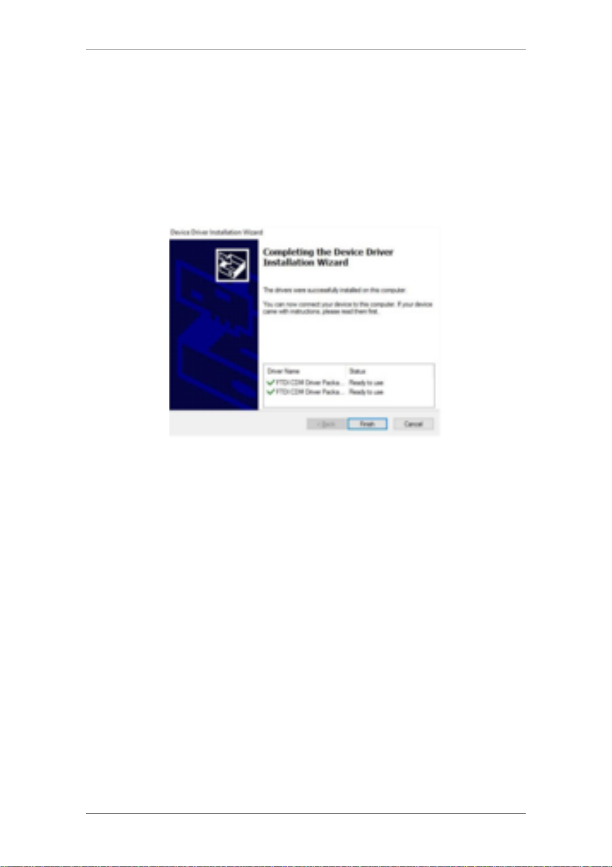
Press the Extract button. Follow all installation including license terms agreement acceptance
shown and the driver will be automatically installed. From a legal point of view, the user must
accept the license terms of the driver. Successful installation is shown in Figure 7 wizard
Figure 2 Driver Installation Completition
Switch on the instrument and make sure it is connected to PC via USB cable. The instrument
appears as UMFT4222PROG within device manager now.

Novomatics Manual Turbitronic P
10
Figure 3 Turbitronic P is realized as UMFT4222PROG USB device
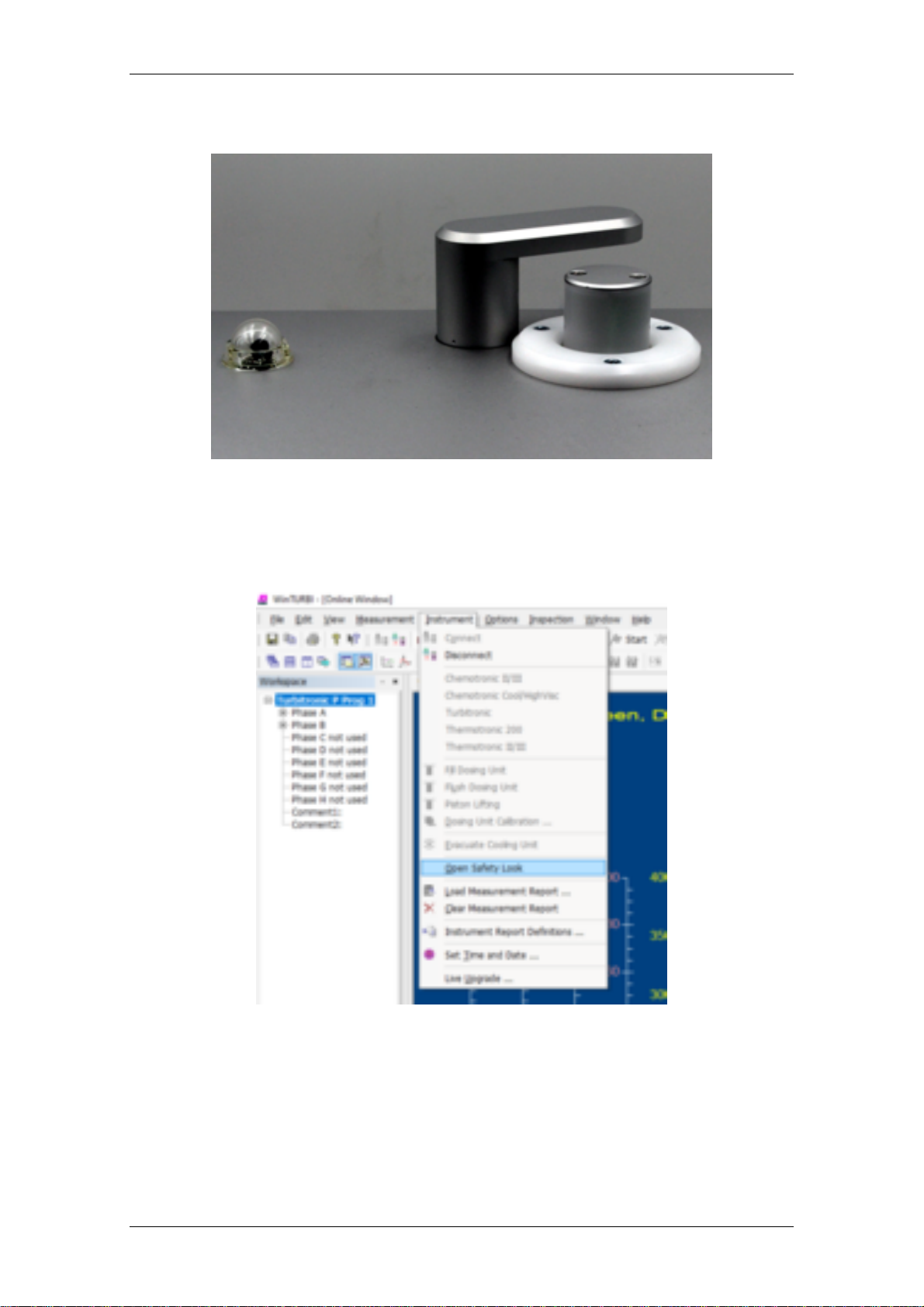
5. Safety Lock – Turbitronic P version
The Turbitronic P measures water based polymers up to temperatures of 150 °C in a pressure
tight samples cell made of glass mainly. During the test the Turbitronic P closes the sample cell
chamber automatically by the safety lock when the samples temperature is higher than 60 °C.
When the temperature decreases 60 °C the sample cell chamber is opened automatically.
Firstly the operator is not being able to remove the hot samples cell under pressure; secondly in
case of unexpected crack the sample cell is kept safely in its fixture.
Before closing the safety lock a red blinks three times. The force of the safety lock is
supervised. In case of a blockage, for example the operator’s finger, it turns back instantly due
to prevent any injury.
Novomatics Manual Turbitronic P
11
Figure 4 Opened Safety Lock
Never try to turn the safety look by hand. It can be damaged. The safety lock can be
opened at higher temperatures on own risk. A warning appears and has to be acknowledged.
Figure 5 Open Safety Lock by operator

Novomatics Manual Turbitronic P
12
6. Principle of temperature measurement
The Turbitronic P determines the sample temperature in direct contact with sample under test. A
pressure tight platinum temperature probe is placed into the glass tube for best thermal
conductivity.
Figure 6 Glass measuring cell with embedded platinum temperature probe
When the sample cell is inserted into the measuring chamber the temperature value is
transmitted wirelessly to the Turbitronic P.
Figure 7 Infrared wireless connection to the instrument

Novomatics Manual Turbitronic P
13
The temperature probe doesn’t require a battery. Its power is supplied by an alternating
electromagnetic field.
Novomatics Manual Turbitronic P
14
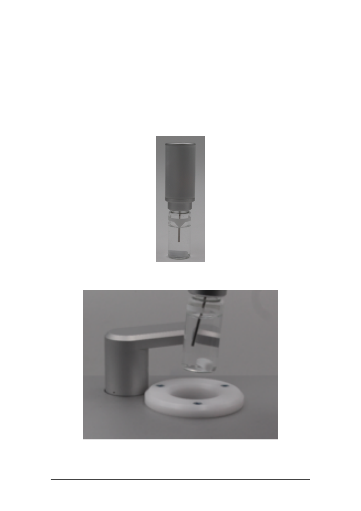
7. Starting a first measurement
The preparation of measuring procedure is simple and quick:
1) Place the stirring bar into the glass tube and fill the tube with the sample under test till
lower corner of white rectangle.
2) Close the glass tube by temperature probe
Figure 8 Prepared measuring tube
3) Insert the measuring tube into the instrument
Figure 9 Inserting prepared measuring tube

Novomatics Manual Turbitronic P
15
4) Go to Measurement/Measurement Preparation … and enter the sample name in one of
the comment fields.
Figure 10 Enter the sample name in one of the comment fields
5) Go to Measurement/Turbitronic/Programs P… and check the program settings of your
program, for example P1.

Novomatics Manual Turbitronic P
16
Figure 11 Check the program settings
These are the program standard settings of main parameter; check these according the
settings above.
1) Usage of heating and cooling phase
2) Final temperature 150 °C using a ramp of 10 K/min
3) Stirring speed 240 rpm
6) Check whether the water inlet and outlet hoses are connected correctly and the water
tap is opened for cooling water flow
7) Make sure your program, for example P1, is selected on toolbar and press the Start
button
8) Now the measurement is started.
9) At the end of test the operator is requested to save the measuring file by suggested file
name *.res

Novomatics Manual Turbitronic P
17
8. Program parameter settings
The actual software version supports up to four phases usable for program design. During
program run the phases are processed one by one. A program consists of at least one phase.
Phase Parameter Function
Speed [rpm] The rotational speed of magnetic field that drives
the magnetic bar
Dwell Time [s] Dwell time at target temperature, it starts when
the sample temperature is closer than 0.5 K to
the final temperature
Final Temp [°C] Final temperature or target temperature of that
phase
dT/dt [K/min] Slope of the temperature ramp, when not AFAP
AFAP The final temperature is achieved as fast as
possible
Stop program Defines this phase as the last
General Parameter Function
Zero NTU as calibrated (xxx) Uses pre-calibration of Zero NTU,
recommended for samples which have initial
turbidity at the start of the program,
Refer to
11.5. Zero calibration
for further details
Auto Calib Zero NTU at start Recommend setting for samples which are clear
initially. An auto calibration is performed for Zero
NTU
Automatic CP detection Automatic cloud point detection is for future use
comments To be printed out on cloud point report
(optionally)
Program Select one of eight programs to be edited
Load and Save File Load and Save single programs from and to a
file
Table 1 Program Parameter Settings
Novomatics Manual Turbitronic P
18
9. Reload a measuring file
The WinTurbi software uses a binary format for measuring results.
1) Go to Window/New 2D-diagram.
2) Click the right mouse button, Add Curve …
3) Add the measurement of your choice
4) Modify axes, colors, etc by clicking right mouse button, Content …
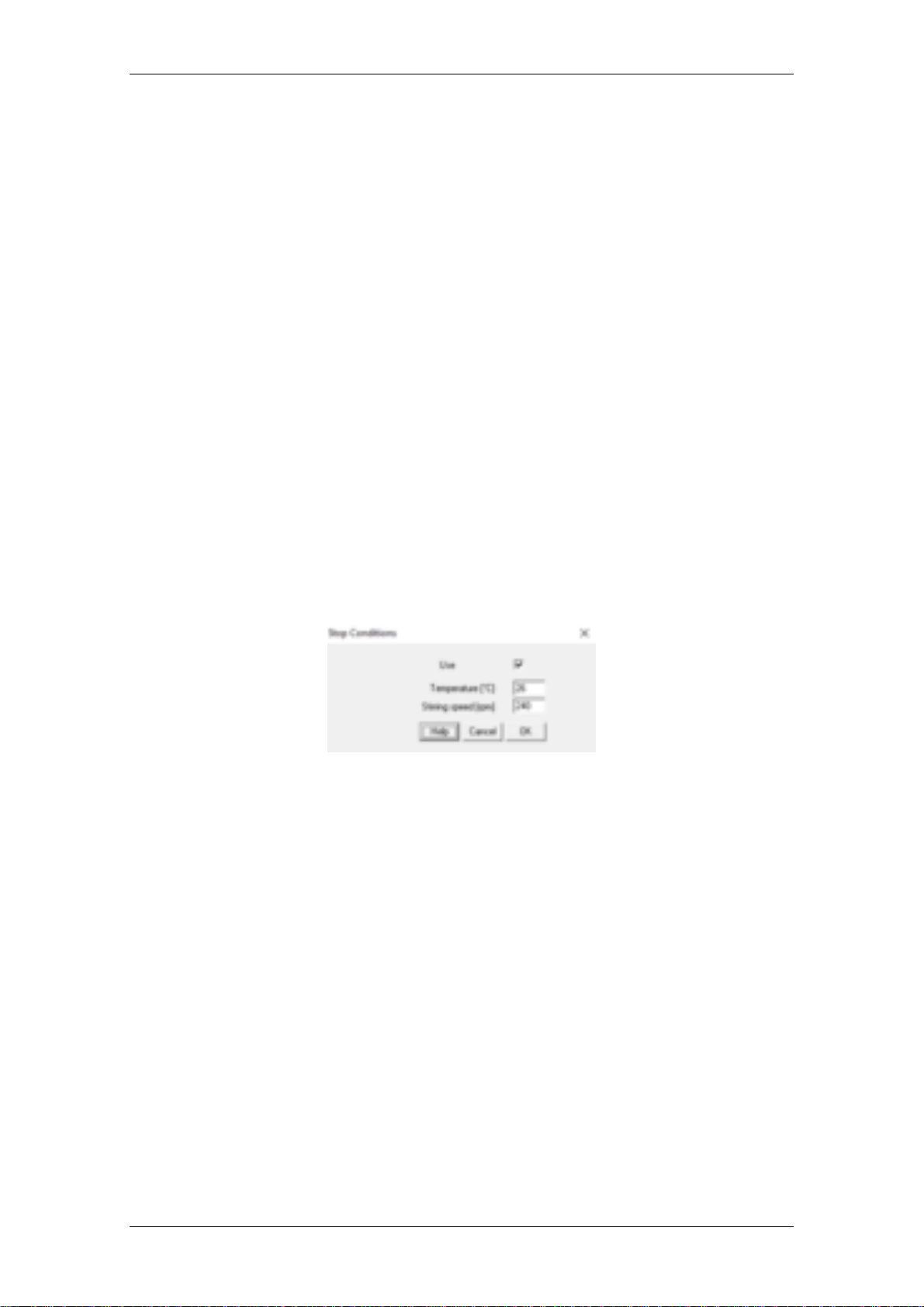
10. Stop settings between the measurements
Best practice is to keep the measuring chamber on low temperature between the
measurements. Further starting the stirrer before the next test starts.
Go to Measurement/Turbitronic/Stops Conditions …
Figure 12 Stop Conditions

Novomatics Manual Turbitronic P
19
11. Calibration of relevant parameters
11.1. Temperature calibration
In the Turbitronic P a powerful microprocessor system is installed for the control of all
instrument functions. The wireless temperature probe is used to convert the analogue inputs of
the platinum sensor into a digital signal which is transferred to the Turbitronic P. The wireless
temperature probe uses internal references for long term stability. In case of any error “----“ is
shown on front panel display. A manual calibration is not required.
11.2. Rotation speed calibration
The speed of the magnetic stirring rod in the test tube is controlled by rotation of a strong
permanent magnet. It is driven by a microprocessor controlled motor. The revolving speed is
displayed on front panel. If a stirring speed is set within the Stop Conditions the magnetic
stirring rod turns already before inserted completely into the measuring chamber. This effect
allows the check of stirring function manually.
11.3. Time calibration
Due to the high accuracy of the built-in real time clock, there will be no short term deviations in
the timing functions.
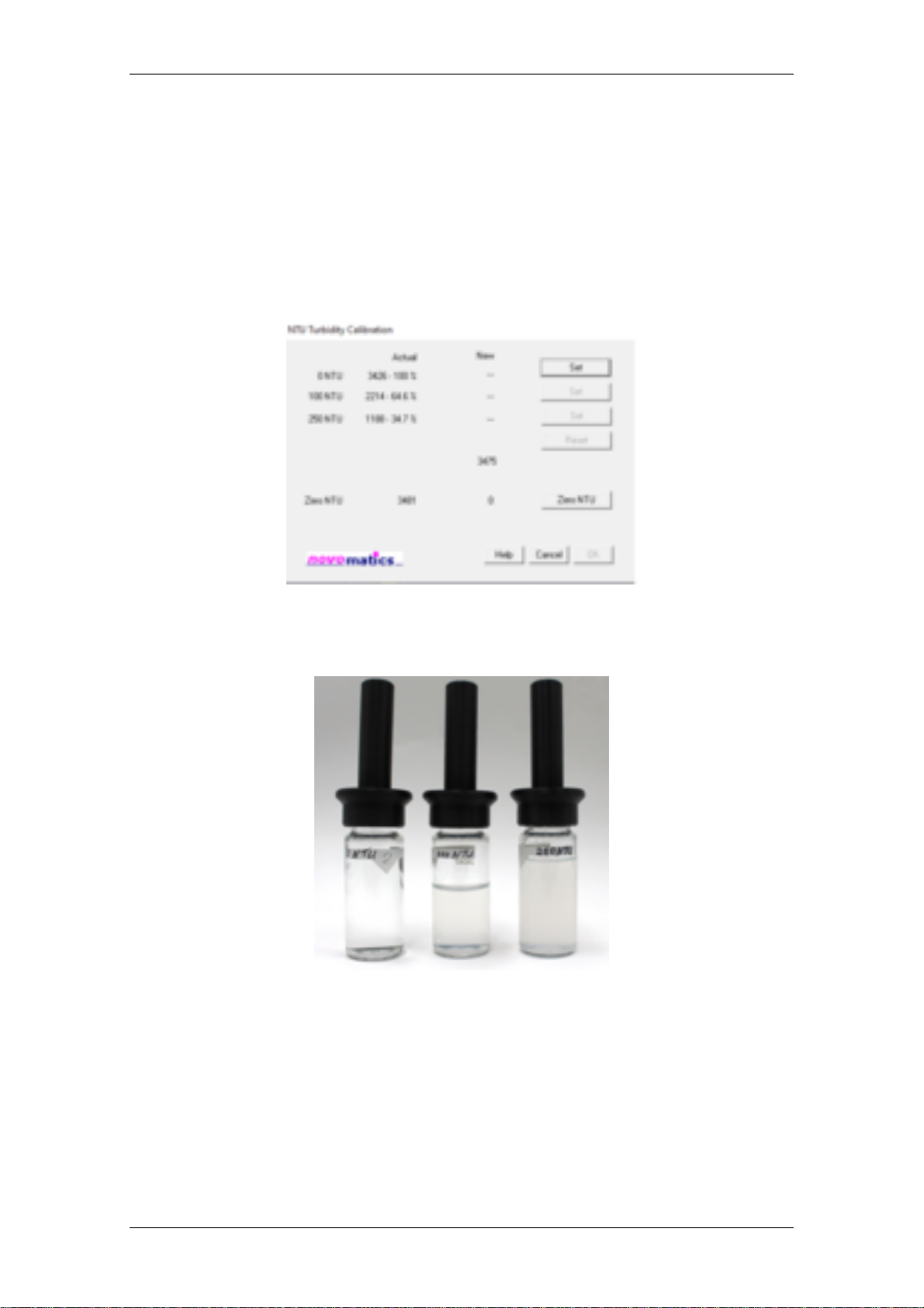
11.4. Turbidity calibration
At start of the test it auto calibration of turbidity is performed, It is assumed the sample has 0
NTU at the start temperature. Further changes in turbidity are related to that. Please make sure
that your sample has really no turbidity at start, if not cool it down till it is completely clear.
The Turbitronic P expresses turbidity in Nephelometric Turbidity Units [NTU]. The value of the
Nephelometric Turbidity Units is calculated by the light transfer through the samples and follows
a non-linear relationship. That’s why the instrument has to be calibrated with three standards.
The Turbitronic P already factory calibrated but the calibration can be approved or re-newed
anytime.
For that purpose prepare three calibration standards according chapter “12. Turbidity calibration
standards” and keep them ready for insertion into the instrument. Please note the three
Novomatics Manual Turbitronic P
20
standards should be inserted without magnetic stirring bar but the tubes should be closed by
temperature probe.
Go to Measurement/Turbitronic/Calib NTU… Insert the three standards 0, 100 and 250 NTU
and press the respective Set button. Release the dialog with OK for taking over the new
calibration. Release with cancel to keep the actual settings valid.
Figure 13 NTU Turbidity Calibration
Figure 14 Samples NTU Turbidity Calibration
11.5. Zero calibration
Zero calibration is required for sample which are already hazy at ambient. Just insert a typical
sample which is definitely clear at room temperature and press the Zero NTU button. Usually
demineralised water is not suitable because its different optical properties compared to typical
This manual suits for next models
1
Table of contents
Other novomatics Measuring Instrument manuals


Popular Measuring Instrument manuals by other brands


Tektronix
Tektronix RSA306B Installation and safety instructions

Extech Instruments
Extech Instruments HD750-NIST user guide

EPA
EPA LW-MK3 Driver installation

Wolfcraft
Wolfcraft 5210000 Translation of the original operating instructions

PV-Engineering
PV-Engineering PVPM 2540C user manual

Sierra
Sierra Innova-Sonic 205 Quick start instructions


