NOVOTEST TP-2020 User manual
Coating Thickness Gauge
NOVOTEST TP-2020
Operating Manual
2021

RDC.OD.TP-2020.000 OM
Operation manual
Coating Thickness Gauge NOVOTEST TP-2020
Page 3
CONTENTS
1 Description and operation of the device and its components.................................................................6
1.1 Application......................................................................................................................................6
1.2 Specification....................................................................................................................................6
1.3 Standard delivery set..................................................................................................................7
1.4 Application of probes......................................................................................................................7
1.5 Composition....................................................................................................................................8
1.6 Design and functioning...................................................................................................................9
1.7 Measuring units, tools, and accessories........................................................................................10
1.8 Marking and sealing......................................................................................................................10
1.9 Packaging......................................................................................................................................10
2 Intended use .........................................................................................................................................11
2.1 Operational limitations..................................................................................................................11
2.2 Preparation for use........................................................................................................................11
2.2.1 Visual inspection....................................................................................................................11
2.2.2 Battery installation.................................................................................................................11
2.2.3 Probe connection....................................................................................................................11
2.3 Intended use ..................................................................................................................................12
2.3.1 Turning on..............................................................................................................................12
2.3.2 Working in «MEASUREMENT» mode................................................................................13
2.3.3 Zeroing of the probe...............................................................................................................14
2.3.4 Working in «CALIBRATION» mode ...................................................................................15
2.3.5 Working in «ARCHIVE» mode.............................................................................................16
2.3.6 Working in «SETTINGS» mode............................................................................................16
2.3.7 Working in «MEMORY CARD» mode ................................................................................17
2.3.8 «INFORMATION» section ...................................................................................................18
2.3.9 Measurements ........................................................................................................................18
2.3.10 Measurements in «CONTROL» mode ................................................................................19
2.3.11 Measurements with averaging .............................................................................................19
2.3.12 Measurement of the depth of cavities and roughness..........................................................20
2.3.13 Measurement of the air temperature, humidity, and dew point...........................................21
2.4 Connection of the device to PC.....................................................................................................21
2.4.1 Software installation ..............................................................................................................21
2.4.2 Working with «AWP TP1M» software .................................................................................22
2.4.3 Data transfer to PC.................................................................................................................23
2.4.4 Data processing on PC...........................................................................................................24

RDC.OD.TP-2020.000 OM
Operation manual
Coating Thickness Gauge NOVOTEST TP-2020
Page 4
3 Maintenance of the device and its COMPONENTS............................................................................27
3.1 Safety precautions.........................................................................................................................27
3.2 Verification ...................................................................................................................................27
3.3 Warranty........................................................................................................................................27
3.3.1 Basic warranty........................................................................................................................27
3.3.2 Extended warranty .................................................................................................................27
3.3.3 Warranty for repaired or replaced parts.................................................................................28
3.3.4 Wearing parts.........................................................................................................................28
3.3.5 Owner obligations..................................................................................................................28
3.3.6 Warranty restrictions..............................................................................................................29
3.3.7 The cases uncovered by warranty..........................................................................................29
3.3.8 Guarantees and consumer law................................................................................................29
3.4 Maintenance of the device ............................................................................................................29
4 Running repairs....................................................................................................................................31
5 Storage .................................................................................................................................................31
6 Transportation......................................................................................................................................31
7 Disposal................................................................................................................................................31

RDC.OD.TP-2020.000 OM
Operation manual
Coating Thickness Gauge NOVOTEST TP-2020
Page 5
Warning!
Please read this instruction manual carefully before using Coating Thickness Gauge NOVOTEST
TP-2020.
The operation manual (hereinafter referred to as «OM») includes general information intended for
acquaintance with information related to the operation of the product – Coating Thickness Gauge
NOVOTEST TP-2020 (hereinafter referred to as the device or thickness gauge). The document contains
specifications, a description of construction and actions, as well as information necessary for the correct
use of the product. Before use, study this document, as the device is to be used by those familiar with
the principles of operation and the design of the device.
To use the testing device properly, the following conditions shall be observed:
−testing methods;
−conditions of testing that meet the testing methods;
−trained user who has read this operation manual.
The manufacturer keeps the right to make minor changes that do not impair the technical
characteristics of the product. These changes may not be mentioned in the text of this document.
The delivery set includes the operation manual and datasheet of the device.
This OM applies to all device models.
RDC.OD.TP-2020.000 OM
Operation manual
Coating Thickness Gauge NOVOTEST TP-2020
Page 6
1 DESCRIPTION AND OPERATION OF THE DEVICE AND ITS COMPONENTS
1.1 Application
The device is intended for measuring the thickness of coatings, parameters of the environment, and
measurement of the depth of cavities and surface roughness.
1.2 Specification
Coating Thickness Gauge NOVOTEST TP-2020 is a portable device with a shockproof body made
of ABS plastic enclosed in a silicon bumper, and a circuit board with electronic components and
batteries. The thickness gauge meets ISO 2808.
The device specifications are shown in the tab. 1.1.
Table 1.1 – Specifications of the device
The range of measured thickness (depending on the type of probe) 0 µm ... 60 mm
Dimensions, max, mm 122×76×37
Power from two NiMH batteries or AA batteries 1.2 V
Amperage, max, mA 100
Time of continuous operation, min, h 20
Weight of the electronic unit and battery, max, g 250
Weight of the probe, max, g 150
Operating temperature, °C -20 … +40
Air humidity, max 98 % at 35 °C
Parameters of test objects:
−surface roughness is not more than Rz 1 (without averaging);
−the minimum curvature radius is 0.3 - 50 mm depending on the used probe.
Body protection
The protection of the device from penetration of solid objects and water meets IP 54 under GOST
14254.
Mean time between failures
The average mean time between failures of the device without reliability index of probes is not less
than 6000 h.
Note – The average mean time between failures of probes is standardized with consideration of
roughness of the surface of the test object Rz = 1.0 µm.
Service life
The complete service life of the device is at least 10 years.
The average service life of probes is at least 2 years.
The criterion of the limiting state is the economic inexpediency of recovery of the device
components by repair.

RDC.OD.TP-2020.000 OM
Operation manual
Coating Thickness Gauge NOVOTEST TP-2020
Page 7
1.3 Standard delivery set
−Processing unit ........................................................................................................................1 pc.
−Probes:
−F-0.3.......................................................................................................................... By order
−F-0.5.......................................................................................................................... By order
−F-2............................................................................................................................. By order
−F-5............................................................................................................................. By order
−NF-2 .......................................................................................................................... By order
−M-12.......................................................................................................................... By order
−M-30.......................................................................................................................... By order
−M-60.......................................................................................................................... By order
−DSH........................................................................................................................... By order
−ST.............................................................................................................................. By order
−STMD........................................................................................................................ By order
−Battery................................................................................................................................... 2 pcs.
−Silicone bumper.......................................................................................................................1 pc.
−Charger....................................................................................................................................1 pc.
−Case.........................................................................................................................................1 pc.
−Operation manual....................................................................................................................1 pc.
* The delivery set can be extended with additional equipment or details at the request of the
customer. The exact information on the delivery set is indicated in the passport of the device.
1.4 Application of probes
Fig. 1.1 show the probes of different types.
F-0.3
F-0.5
F-2
F-5
NF-2
M-
12
M-30
M-60
DSH
ST
STMD
Figure 1.1 – Probes
F probe
The probe is intended to measure the thickness of dielectric and electrically conductive non-
ferromagnetic and galvanic coatings on electrically conductive ferromagnetic substrates.
NF probe
The probe is intended to measure the thickness of dielectric coatings and electrically conductive
non-ferromagnetic coatings on electrically conductive non-ferromagnetic substrates.
M probe
The probe is intended to measure the thickness of thick dielectric coatings (bitumen, resin, etc.) on
ferromagnetic and non-ferromagnetic substrates.

RDC.OD.TP-2020.000 OM
Operation manual
Coating Thickness Gauge NOVOTEST TP-2020
Page 8
ST probe
The probe is intended to measure the temperature of metal surfaces.
STMD probe
The probe is intended to measure the air temperature, air humidity, and dew point.
DSH probe
DSH probe is intended to measure the depth of cavities and evaluation of the surface roughness.
The metrological parameters of probes are shown in the tab. 1.2.
Table 1.2 – Metrological characteristics of probes
Type Measurement range Measurement error Application
F-0.3 0-300 µm ±(0.03h+0.001) mm Testing of paint, varnish and
galvanic coatings
F-0.5 0-500 µm ±(0.03h+0.001) mm
Testing of paint, varnish and
galvanic coatings
F-2 0-2000 µm ±(0.03h+0.002) mm
Testing of paint and varnish
coatings
F-5 0-5000 µm ±(0.03h+0.002) mm Testing of paint, varnish and
mastic coatings
M12 0-12000 µm ±(0.03h+0.01) mm Testing of mastic coatings
M30 0-30000 µm ±(0.03h+0.02) mm Testing of mastic coatings
M60 0-60000 µm ±(0.03h+0.03) mm Testing of mastic coatings
NF-2 0-2000 µm ±(0.03h+0.002) mm Testing of anodic oxide films
and paint coatings
ST -40…+80 °C ± 1 °C
Testing of the surface
temperature
STMD -40…+80 °C
humidity: 0-100 %
dew point: -15…+40 °C
± 1 °C
± 5 %
± 2 °C
Testing of temperature, air
humidity, and dew point
DSH 2-300 µm ±(0.03h+0.002) mm Testing of surface roughness
after sandblasting and shot
blasting
where h – nominal value of the coating thickness or the depth of a cavity, mm.
Note – The operating temperature range of the electronic unit of the coating thickness gauge differs
from the temperature range of the ST and STMD probe and it is -20…+40 °C. The measurement of the
air temperature, humidity, and dew point in conditions exceeding the permissible range of the electronic
unit is allowed only if a probe is used in these conditions.
1.5 Composition
Coating Thickness Gauge NOVOTEST TP-2020 is a portable device with a graphic display and
keyboard with connected probes. The external view of the device is shown on fig. 1.2.
RDC.OD.TP-2020.000 OM
Operation manual
Coating Thickness Gauge NOVOTEST TP-2020
Page 9
1
2
3
4
7 8
9
5 6
10
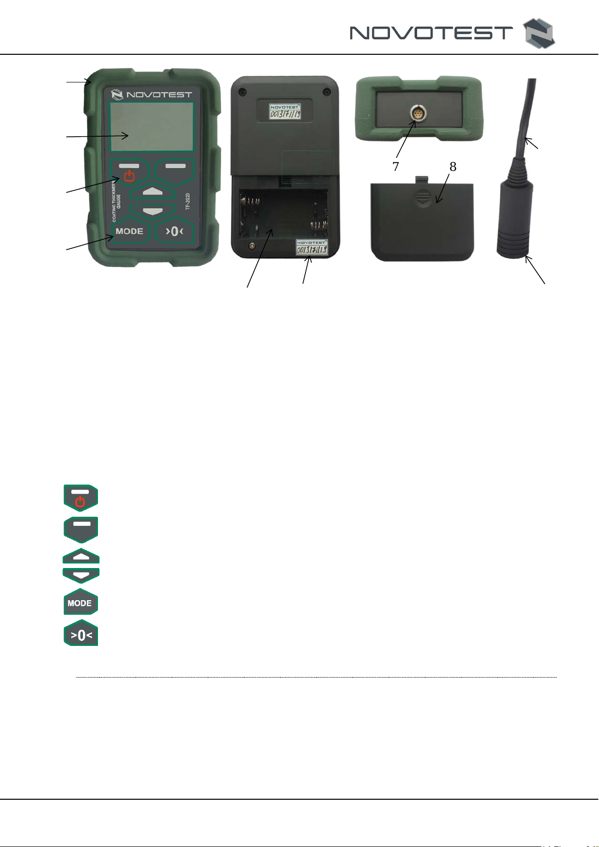
1 – silicone bumper; 2 – graphic display; 3 – keyboard; 4 – processing unit; 5 – battery compartment;
6 – serial number of the device;7 – socket for probes; 8 – battery compartment cover; 9 – connection
cable; 10 – probe.
Figure 1.2 – Coating Thickness Gauge NOVOTEST TP-2020
The device consists of the processing unit (4) and probe (10) connected via socket (7). The socket
for probes (7) is located on the top part of the body. The keyboard (3) is located on the front panel, as
well as the graphic display (2). The battery compartment (5) is located in the back lower part of the
device, and the batteries themselves.
The keyboard buttons and their functions
– turning on and off / left functional button;
– right functional button;
– navigation up in the device menu/selection of the measuring unit;
– navigation down in the device menu/selection of dimensions of the measuring unit;
– selection of operating mode;
– the probe zeroing.
1.6 Design and functioning
The device functioning depends on the probe used.
When the parametric probe is used (NF, M, DSH), the functioning is based on the measurement of
the generator that includes the coil of eddy current parametric probe. The generation frequency depends
on the coating thickness. The measured frequency is converted into the thickness value and shown on
the graphic display.
When the induction probe is used (F), the current impulse is generated in the primary coil of the
probe by the command from the controller. The electromotive force (EMF) is generated on the secondary

RDC.OD.TP-2020.000 OM
Operation manual
Coating Thickness Gauge NOVOTEST TP-2020
Page 10
coil. The generated EMF (the function of thickness) goes to the controller and is converted into the
thickness value. The coating thickness shows on the display.
Measurement accuracy
The measurement accuracy depends on the right consideration of the physical properties of the test
object and its homogeneity, temperature, roughness, surface geometry, and other parameters. The error
is specified for each probe in the tab. 1.2.
Operating mode
The device has a specific operating mode for each probe, and two modes common for all probes:
single measurement, and measurement with averaging.
1.7 Measuring units, tools, and accessories
The performance of the device is assessed by checking the modes of its operation and checking the
possibility of measuring the thickness by the thickness blocks (reference blocks). The discrepancy
between the readings of the device should not exceed the permissible error (tab. 1.2). If a permissible
error is exceeded, the device should be calibrated under c. 2.3.8.
The adjustment and setting of the device in case of malfunction shall be performed by the
manufacturer.
1.8 Marking and sealing
The device has the sealing established by the manufacturer.
The symbol of the device with the trademark of the manufacturer is applied to the front panel of the
device. The serial number is printed on the back panel.
1.9 Packaging
The electronic unit and the probe are delivered in a package (case), excluding their damage during
transportation.
To avoid mechanical damage to the cable and connectors of the device, disconnect the probe from
the device before placing it in the packaging container.
RDC.OD.TP-2020.000 OM
Operation manual
Coating Thickness Gauge NOVOTEST TP-2020
Page 11
2 INTENDED USE
2.1 Operational limitations
The device should be operated under the influence of factors and taking into account the parameters
of the test object under the specified technical characteristics, and the device must be used within its
specification.
The device shall be operated only by a qualified user familiar with the operation manual.
After transporting the device to the place of operation at a negative ambient temperature and placing
it into a room with a positive temperature, keep the device in its packaging for at least 6 hours to avoid
failure due to the moisture buildup.
2.2 Preparation for use
2.2.1 Visual inspection
Inspect the device visually and make sure that there is no mechanical damage to the processing unit
(4), probe (10), connector (7), and connecting cable (9).
2.2.2 Battery installation
Place a battery into the battery compartment (5) after pushing and pulling down the cover of the
battery compartment until detaches. The power element or batteries should be placed in line with the
polarity indicated on the device. Close the battery compartment cover until it snaps into place.
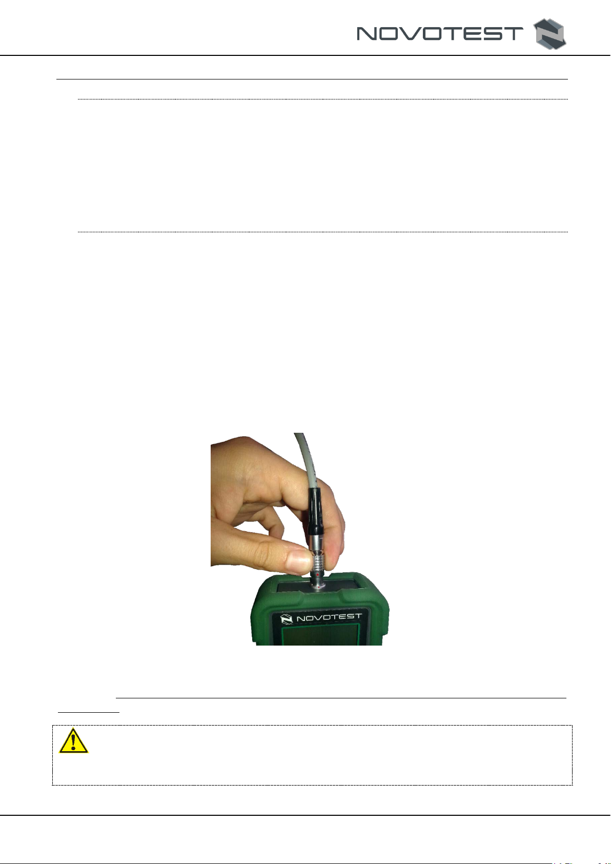
2.2.3 Probe connection
Connect the used probe (10) by plugging the connection cable (9) into the probe socket (7) on the
processing unit (4) so that the red dots on the plug and socket are aligned (fig. 2.1).
Figure 2.1 – The probe connection
Note – The probe can be connected and disconnected from the electronic unit only with the device
powered off.
Warning!
To prevent damage to connectors and cables, follow the instructions for handling those connectors
below!
The connectors used in the device (fig. 2.2) consist of two parts: socket and plug (pin) of the cable.

RDC.OD.TP-2020.000 OM
Operation manual
Coating Thickness Gauge NOVOTEST TP-2020
Page 12
Figure 2.2 – Connectors of the device
Connection and disconnection of socket and plug is shown in fig. 2.3.
Warning!
When disconnecting the plug from the socket, grasp its housing in a corrugated area, do not pull the
cable!
Figure 2.3 – Manipulating connectors
2.3 Intended use
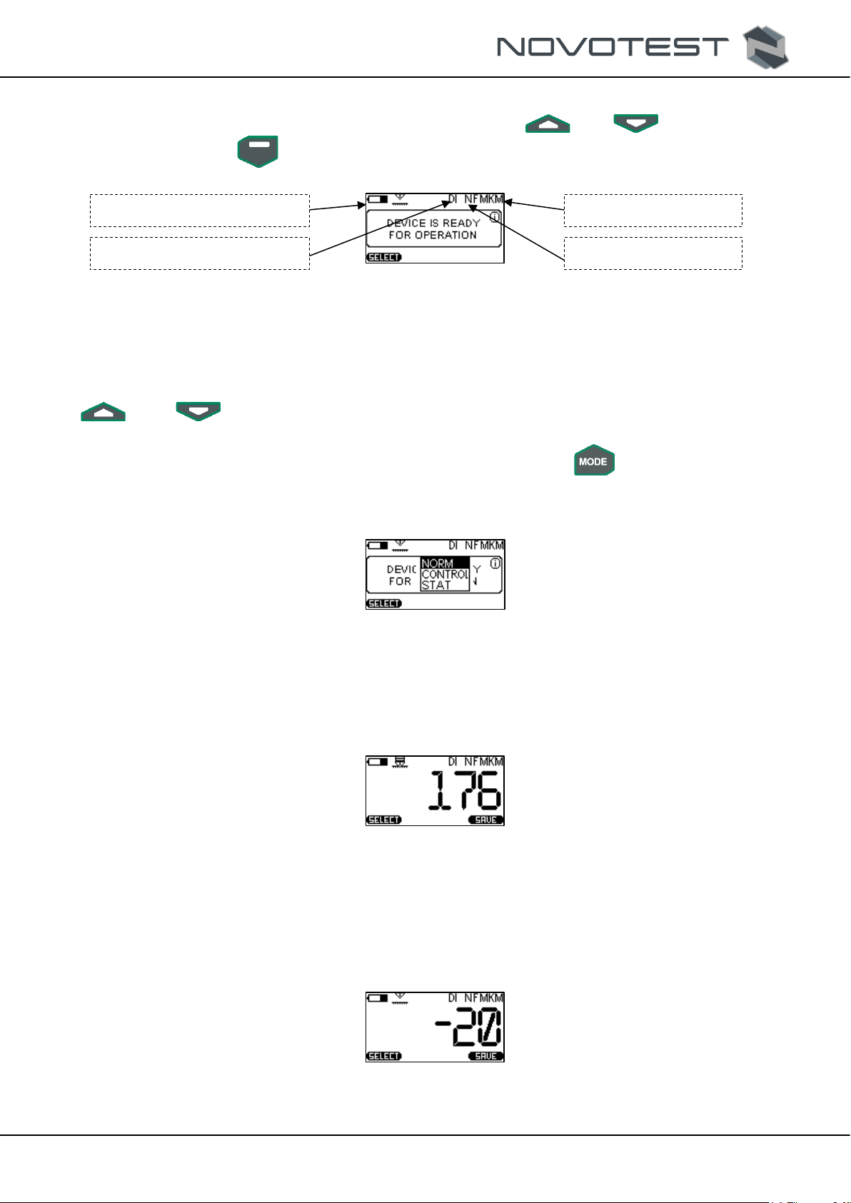
2.3.1 Turning on
Turn the device on by pressing « » on the control panel until a short-term splash screen appears
on the display (fig. 2.4).
Figure 2.4 – Splash screen
Then, the device will go to the main menu (fig. 2.5). To select the menu item, use « » or «
», and confirm the selection by pressing « ».
Figure 2.5 – The main menu of the device
Functional buttons
RDC.OD.TP-2020.000 OM
Operation manual
Coating Thickness Gauge NOVOTEST TP-2020
Page 13
2.3.2 Working in «MEASUREMENT» mode
To enter «MEASUREMENT» item, select it by pressing « » or « », and confirm the
selection by pressing « », then the device will go to the «MEASUREMENT» section (fig. 2.6).
Figure 2.6 – «MEASUREMENT» mode
In the «MEASUREMENT» mode, the device shows the battery charge, material of substrate and
coating, measuring unit, and measurement value.
The measuring unit (mm, µm, inches, miles) are installed in the «SETTINGS» section, «Scale»
parameter. The measurement value can be also installed in the «MEASUREMENT» section by using «
» and « » buttons. The quick pressing of a button switches the measuring unit. The selected
unit shows on the graphic display.
The measured data can be displayed in several modes (see c. 1.7), « » button is used to switch
between the modes, and when the button pressed, the menu of displaying modes will appear on the
screen: «NORM», «CONTR», and «STAT» (fig. 2.7).
Figure 2.7 – Selection of displaying modes
2.3.2.1 «Normal» mode
In this mode, the device will show the current measurement value or averaged value of the series of
measurements (fig. 2.8), depending on the settings.
Figure 2.8 – Displaying of the result in «Normal» mode
2.3.2.2 «Control» mode
This mode is used when the coating should be tested with the limits (fig. 2.9). During measurement,
the display will show the difference between the measured and reference thickness, after analyzing the
operator will make conclusions of the quality of the coating.
Figure 2.9 – Displaying of the difference of thicknesses in the «Control» mode
Battery charge
Coating material
The measured value
The base material
RDC.OD.TP-2020.000 OM
Operation manual
Coating Thickness Gauge NOVOTEST TP-2020
Page 14
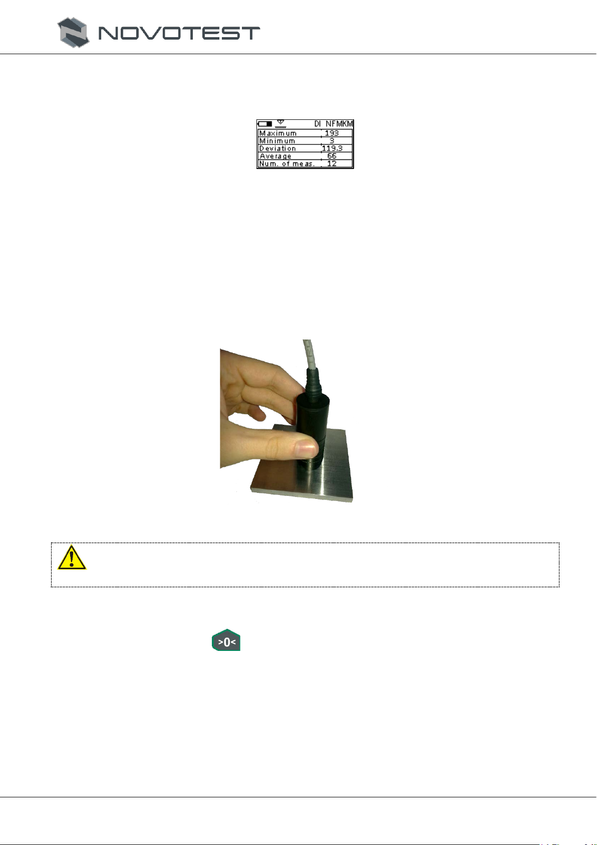
2.3.2.3 «Statistics» mode
«Statistics» mode (fig. 2.10) allows viewing the following parameters of measurements: maximum
and minimum value, deviation, average value, number of measurements.
Figure 2.10 – The display in «Statistics» mode
2.3.3 Zeroing of the probe
If operating conditions change (the ambient temperature changes considerably), the electrical
conductivity of the base material changes, or if the probe is switched on for the first time, the probe
should be zeroed. To do that, do the following steps:
1. Prepare an uncoated sample of the test object or structure, similar or close by geometric and
electrical properties, type of machining, or design of the tested part.
2. Then, set the probe on the prepared sample or object without coating upright, and push it down
(fig. 2.11) without wiggling.
Figure 2.11 – Setting of the probe on the uncoated object
Warning!
Do not move the probe along the test object (scan) during the measurement.
3. When the device will make measurement and the sound signal will be generated, remove the
probe from the test object. The display will show the measurement result.
4. Then, press the button « », and the display will show the message: 0.000 (00.00; 000.0; or
0, depending on the type of probe and selected value).
5. Check the accuracy of the zero setting, by re-testing the product without coating. The readings
should be in the range from 0 to 2 µm.
6. Then, make a measurement on the reference block from the kit. The device readings shall
correspond to the thickness of the used block, with consideration of the permissible error. If the
device reading, calibrate the device according to c. 2.3.3.
RDC.OD.TP-2020.000 OM
Operation manual
Coating Thickness Gauge NOVOTEST TP-2020
Page 15
2.3.4 Working in «CALIBRATION» mode
To ensure that the measurement error meet the value in the datasheet during the testing of coating,
user should set the device according to properties of substrate and coating.
Warning! The factory settings of the device correspond to the following:
– for inductive probes F and parametric probes M – dielectric coatings on Page 3 (P. 10. P.20. P.
30. P45);
– for parametric probes NF – dielectric coating on aluminum D16T (D16, AmG6, AK6).
Note – It is recommended to create a backup copy of the calibrations before calibration to resume
proper calibration in the event of incorrect settings. (c. 2.3.7).
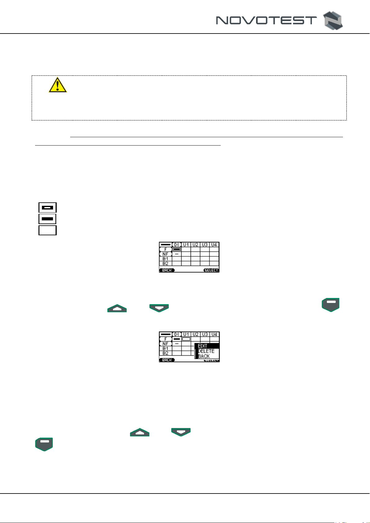
When entering the «Calibration» section, the table like on fig. 2.12 will be displayed, where each
cell corresponds to the base material of calibration (Ferromagnetic base, Non-ferromagnetic base, Base
1, Base 2) for a specific material of coating (Dielectric coating, Coating 1, Coating 2, Coating 3, Coating
4). The calibration cells have three conditions:
– Calibration;
– Custom graduation;
– Empty cell.
Figure 2.12 – «CALIBRATION» section
Using the buttons « » and « », select the cell for calibration, then by pressing « »
enter «menu» of calibration (fig. 2.13), and press «EDIT».
Figure 2.13 – Calibration menu
Prepare a sample for calibration, for which on the base firmly lay a coating measure with a nominal
value. Set the probe on the prepared sample and make at least 5 measurements. The device receives
nominal codes making measurements and the purpose of the calibration is to find the correlation between
the nominal code and the value of the coating thickness.
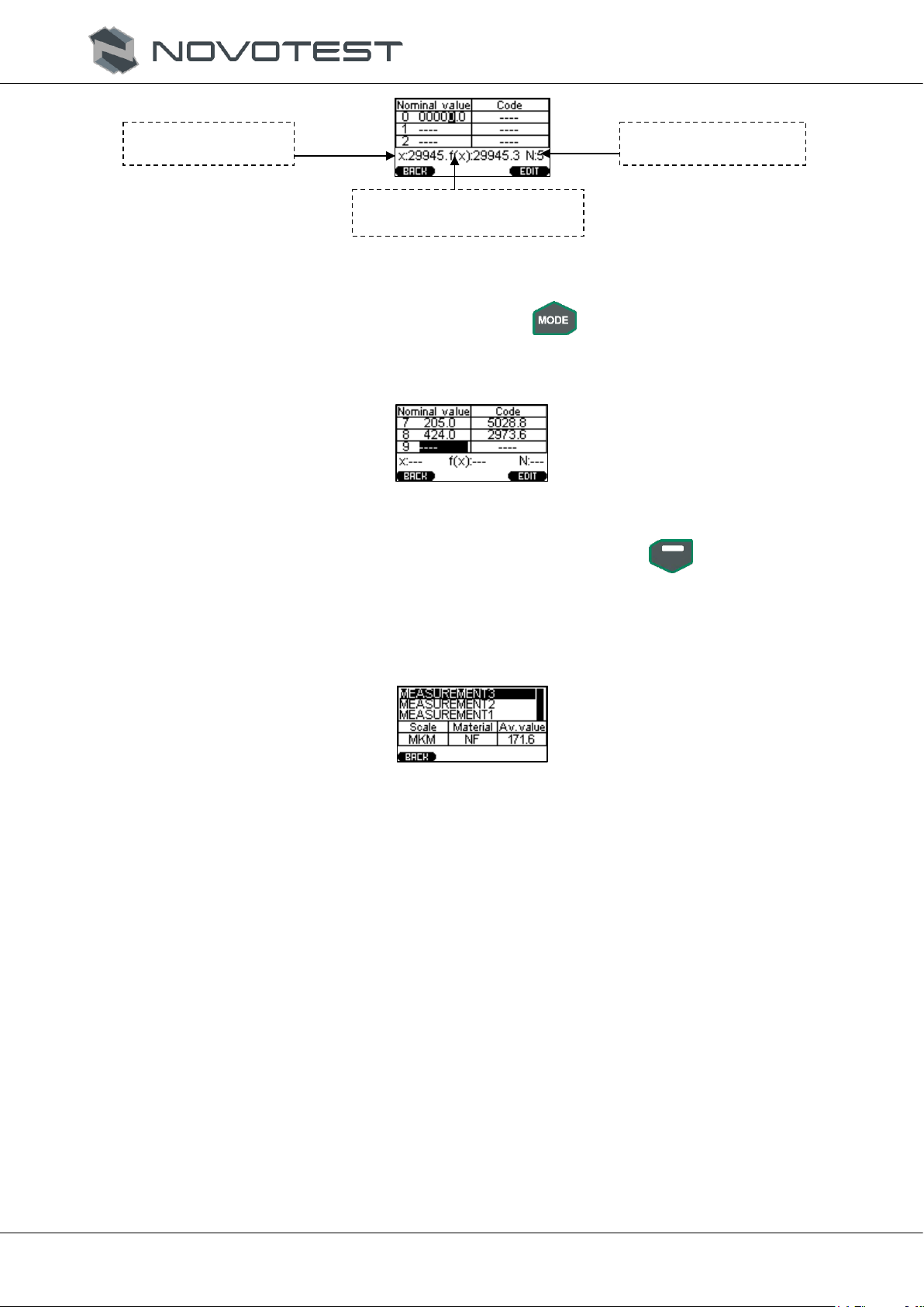
When the measurements are done, enter the nominal value by pressing «EDIT», and enter the actual
value of thickness by pressing « » and « » (fig. 2.14). To enter the next value, use «
» button.
RDC.OD.TP-2020.000 OM
Operation manual
Coating Thickness Gauge NOVOTEST TP-2020
Page 16
1.
Figure 2.14 – Calibration of the first value
If the obvious error appears after measurement, press « » and select «RESET», and the series
of measurements will be removed.
Then, do the same actions with other blocks (fig. 2.15).
Figure 2.15 – Calibration by three reference blocks
To save the calibration, press «back» and confirm saving by pressing « ».
2.3.5 Working in «ARCHIVE» mode
When the «Archive» mode is selected, the device goes to viewing of the saved measurements (fig.
2.16). The device memory can save up to 1024 measurements.
Figure 2.16 – Viewing of the saved measurements
2.3.6 Working in «SETTINGS» mode
When the «SETTINGS» item is selected, the device goes to settings of the following parameters
(fig. 2.17):
−«LANGUAGE»: selection of the language of the device menu (English, Russia, and others
are available);
−«BRIGHTNESS»: changing of the display brightness (from 0 to 100%, discreteness 10%);
−«CONTRAST»: changing the display contrast (from 0 to 100%, discreteness 10%);
−«AUTO OFF»: setting of the automatic shutoff when the device is not used (OFF, 1 min,
5 min, 10 min, 30 min);
−«SOUND»: setting of the sound signal when pressing of buttons and measurement
(Key +Meas., Meas., Key, OFF);
−«RETRO»: allows returning to the measurement mode with the latest measurements after
the device rebooting;
−«SCALE»: selection of a measuring unit (mm, mkm, inch, mil);
−«MAT. BASE»: selection of the substrate of the test object (F – ferromagnetic base, NF –
non-ferromagnetic base, B1, B2);
−«MAT. COVER»: selection of the coating material of the test object (DI – dielectric coating,
and user coatings: U1, U2, U3, U4);
Current code value
The obtained value of the
function (polynomic)
Measurement number

RDC.OD.TP-2020.000 OM
Operation manual
Coating Thickness Gauge NOVOTEST TP-2020
Page 17
−«MODE»: allows choosing the measurement mode (Current, Average).
Figure 2.17 – «SETTINGS» section
2.3.7 Working in «MEMORY CARD» mode
The device has the memory function intended for saving the measurement results in the device
memory.
2.3.7.1 Calibration backup
When going to «Memory card» section, the device goes to the memory menu (fig. 2.18).
Figure 2.18 – Backing up of calibrations
It is recommended to back up the calibration before calibrating the factory settings of the probe.
This is needed to resume proper calibration after incorrect settings.
2.3.7.2 Downloading of calibration backups
The saved calibrations can be downloaded from the probe memory. This function is needed to
resume calibration in case of wrong settings of the probe (fig. 2.19).
Figure 2.19 – Downloading of the calibration backup
2.3.7.3 Clearing of memory card
When this clause is selected (fig. 2.20), the data saved in the archive will be cleared. The archive
will be empty after clearing SD card.
Figure 2.20 – Memory card clearance menu
2.3.7.4 Memory condition
When the menu item «Memory state» (fig. 2.21) is selected, the table with possible number of
measurements is shown, including already saved and free for storage (fig. 2.22).

RDC.OD.TP-2020.000 OM
Operation manual
Coating Thickness Gauge NOVOTEST TP-2020
Page 18
Figure 2.21 – Viewing of the memory condition
Figure 2.22 – Viewing of the memory condition
2.3.8 «INFORMATION» section
In this menu item, user can view the serial number of the device and probe and the firmware version
of the thickness gauge (fig. 2.23).
Figure 2.23 – Viewing of the factory numbers of the device and probe, and the firmware version
2.3.9 Measurements
1. Connect the probe and turn the device on by pressing « ».
2. Zero the probe (see c. 2.3.3).
3. Set the probe on the test object or coated part upright, and press it to down (fig. 2.24) without
wiggling.
Figure 2.24 – Setting the probe on the coated object
4. When the device makes a measurement, the sound signal will be generated, and the display will
show the measurement result.
5. Once the repeated signal will sound, the device will be ready for the new measurement. The
display will show the recent measurement of the coating thickness (fig. 2.25), changing only
upon the next measurement.

RDC.OD.TP-2020.000 OM
Operation manual
Coating Thickness Gauge NOVOTEST TP-2020
Page 19
Figure 2.25 – Graphic display after measurement
The thickness gauge features only «AUTO OFF» function that is installed in the «SETTINGS»
section. If measurement was not performed, and the device was idle for a specific time (1 min., 5 min.,
10 min., 30 min.), the device will be turned off automatically.
6. To turn the device off, press and hold « ».
2.3.10 Measurements in «CONTROL» mode
When making measurements in «Control» mode, the display will show the difference of thicknesses
with positive or negative value, by which the measured thickness of coating differs from the reference
one.To measure the coating thickness, do the following steps:
1. Prepare the reference block with coating.
2. Connect the probe and turn the device on by pressing « ».
3. Enter measurements mode, press « », and select «CONTROL» in the appeared menu.
4. Set the probe on the prepared object upright and press firmly. When the device makes a
measurement, put the probe away from the object and zero the probe by pressing « ».
5. Check the accuracy of zero setting and make sure that the readings of the device do not exceed
±2 µm.
6. Measure the test object. If the coating thickness is identical to the coating thickness of reference
block – the device display will show 0. If the thickness of coating of the test object is less than
thickness of coating of the reference block, the display will show the difference of thicknesses
with negative value (fig. 2.26). When the coating is thickened, the display will show the
difference of thicknesses with positive meaning.
Figure 2.26 – Working in «Control» mode
2.3.11 Measurements with averaging
The automatic averaging mode means that, after each measurement, the device will include this
result in the set of averaged values.
To enter the working mode with the automatic averaging of the measurement results, set the
«AVERAGE» mode in «SETTINGS» section. Now, the necessary number of measurements can be
done, and after each measurement, the device will calculate the average value and show the readings on
the display.
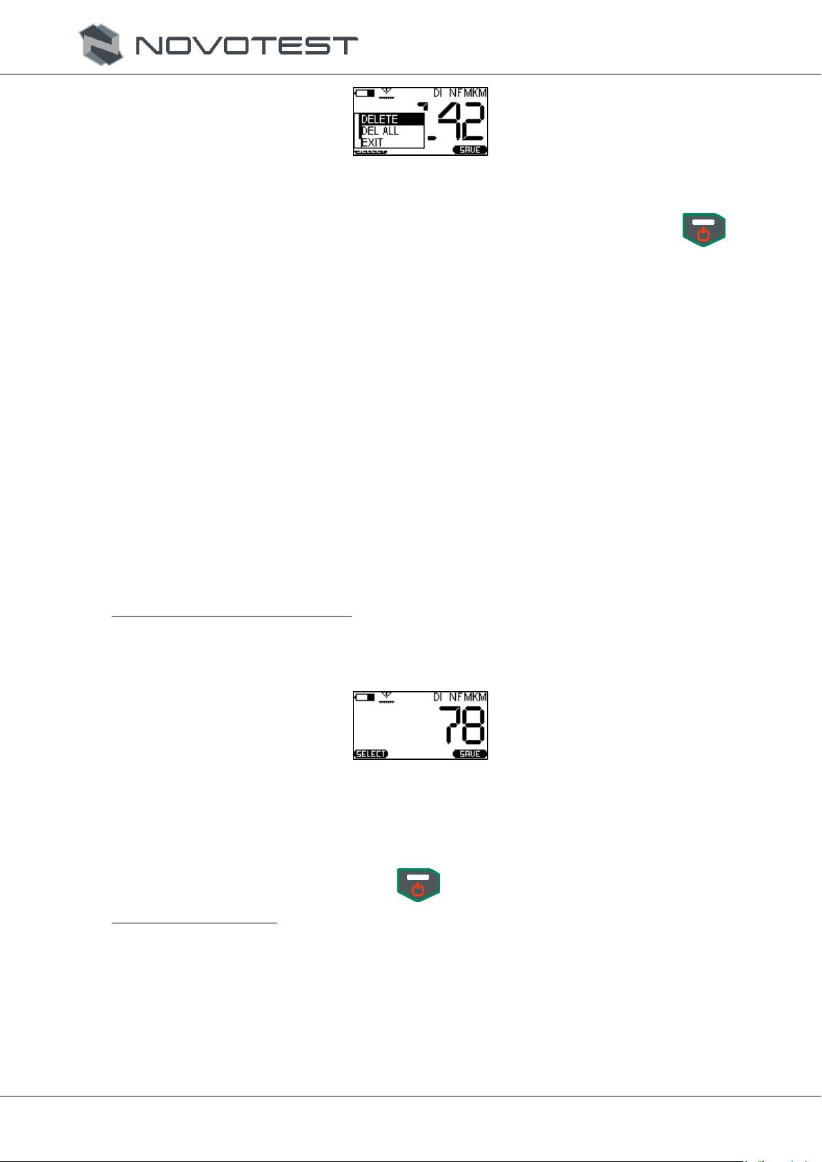
To remove the current measured value, press « », and the menu of selection of actions will be
opened (fig. 2.27), where you should choose «DELETE» parameter. The latest measurement will be
removed from the measurement series.
RDC.OD.TP-2020.000 OM
Operation manual
Coating Thickness Gauge NOVOTEST TP-2020
Page 20
Figure 2.27 – Menu of selection of actions
To completely remove the average value and start the new measurement series, press « » and
select «DEL ALL». Now, you can start the new measurement cycle with the average value.
To exit the measurement mode with averaging, set «CURRENT» in the «SETTINGS» section.
2.3.12 Measurement of the depth of cavities and roughness
The DSH probe works by the principle of a profile gauge. The measurement value displayed is the
distance between the measurement needle and the basic surface of the probe.
By setting the probe needle into cavities, pits, etc. their depth can be measured.
By making at least ten measurements along the line on the surface in the averaging mode (c. 2.3.11),
user can evaluate the roughness of this surface by Rz parameter.
To match the readings of the device with the actual ones when evaluating the surface roughness or
measuring the depth of the grooves, calibrate the probe on a polished base. The surface roughness must
be Ra 0.32 µm. The probe calibration provides for the zero setting, (c. 2.3.3).
To make measurement, do the following step:
1. Connect the DSH probe to the device (2.2.3).
2. Turn the device on (2.3.1).
3. Set the base material in the device settings – «Non-ferromagnetic base», and set the coating
material to «Dielectric coating».
4. Set zero on the polished base (Ra≤0.32 µm), under c. 2.3.3.
Measurement of the depth of cavity:
5. Set the probe on the prepared block or part upright and push it down without wiggling.
When the device makes a measurement, the sound signal will be generated, and the display will
show the measurement result (fig. 2.28).
Figure 2.28 – The graphic display after measurement with DSH probe
6. To start a new measurement, lift the probe into the air, and another single signal will sound,
then the device is ready for a new measurement. The indicator shows the last measurement
result which changes only during the next measurement.
7. To turn the device off, press and hold « ».
Evaluation of roughness:
1. Enter the mode with averaging (c. 2.3.10).
2. Set the probe on the prepared block or part upright and push it down without wiggling.
3. When the device makes measurement, the signal will sound, and the display will show the
measurement result.
4. To start the new measurement, put the probe into the air. The display will show the latest
measurement result, changing only with the next measurement.
5. Make at least ten measurements along the line on the surface, and the averaged value will
indicate the roughness Rz.

RDC.OD.TP-2020.000 OM
Operation manual
Coating Thickness Gauge NOVOTEST TP-2020
Page 21
6. To turn the device off, press and hold « ».
2.3.13 Measurement of the air temperature, humidity, and dew point
The air temperature, air humidity, and dew point should be measured with the STMD probe.
To measure the air temperature, humidity, and dew point, do the following steps:
1. Connect the STMD probe to the device (c. 2.3.3).
2. Holding the probe by the handle (where parameters should be measured), make measurement
before turning the device on and holding « » button until the screensaver appears.
3. After turning on, the device will start measurements automatically.
4. The display will show the measurement results (fig. 2.29).
Figure 2.29 – The graphic display when using the STMD probe
5. To turn the device off, press and hold « ».
2.4 Connection of the device to PC
2.4.1 Software installation
Connecting the device to a PC, user can transfer the information stored on the memory card to a PC.
To connect the device to a PC:
1. Copy the driver «CP210x_VCP_Windows» and the program «AWP TP1M» (archives of .zip
and .rar format) to the hard drive of the PC or download the current versions from the official
website.
2. After downloading, unzip the data, and two folders will be obtained: driver and program (fig.
2.30).
Figure 2.30 – The downloaded software
3. Install the driver to PC.
Note – After notice about successful driver installation, it is advisable to restart a PC.
4. Now, user can connect the device to a PC by using the USB cable from the delivery set. After
connection, the computer will detect the new device and install the driver to use it.
5. Install the program to use the device, to do that, launch the program installation file (setup.exe)
from the folder «AWP TP1M», and press «INSTALL» (fig. 2.31).
Air humidity
Air temperature
Dew point
Table of contents
Other NOVOTEST Measuring Instrument manuals


Popular Measuring Instrument manuals by other brands


PCB Piezotronics
PCB Piezotronics 134A22 Installation and operating manual

Hach
Hach LANGE 5130 quick start guide

Chauvin Arnoux
Chauvin Arnoux C.A 846 user manual

Siemens
Siemens SITRANS FUS060 HART operating instructions

YOKOGAWA
YOKOGAWA 701944 user manual

Larson Electronics
Larson Electronics LZRWL-CRN-RED-100MW instruction manual


