Novus Kronos I User manual

USERS
MANUAL
NR9000
Kronos 1
REVISION
C
DATE
2/22/23
Page 1of 59
www.novuspower.com
NR9000
Kronos Ι
10MHz Rubidium Frequency Reference, High Performance, Low
Noise, GNSS-Locked
All information provided herein is the property of Novus Power Products LLC. The information
included may be reproduced without the permission of Novus Power Products LLC. for the
purpose of operating the equipment.

USERS
MANUAL
NR9000
Kronos 1
REVISION
C
DATE
2/22/23
Page 2of 59
www.novuspower.com
Table of Contents
Safety.....................................................................................................................................................4
Mounting................................................................................................................................................5
Summary...............................................................................................................................................6
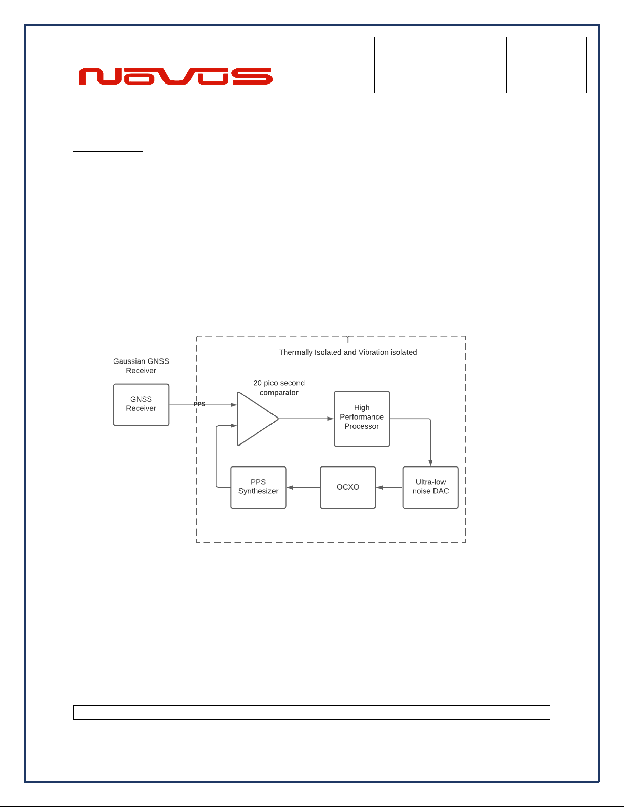
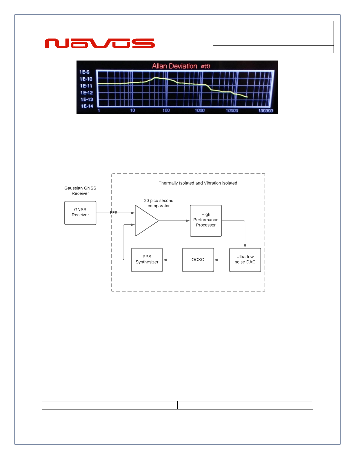
Thermally Isolated Reference (HS3).........................................................................................................9
Controls and Indicators......................................................................................................................13
Front Panel......................................................................................................................................13
LEDs.............................................................................................................................................13
Navigation Paddle....................................................................................................................... 13
Menu Layers....................................................................................................................................14
Display Navigation..............................................................................................................................15
Time and Date................................................................................................................................. 15
Analog Clock Face......................................................................................................................16
Time Display Preference................................................................................................................16
GNSS Data Display........................................................................................................................ 17
GNSS MultiBand SNR Meter.........................................................................................................19
Survey Mode...................................................................................................................................20
Frequency Data, Reporting, and Monitoring ................................................................................ 21
Frequency Statistics.......................................................................................................................23
Save Now Button ........................................................................................................................24
Clear Stats Button.......................................................................................................................24
Frequency Statistics History.......................................................................................................25
Latch Channel Values ....................................................................................................................27
Setting Amplitude and Threshold Alert .........................................................................................28
Amplitude Reference Point ........................................................................................................29
Threshold Alert Point.................................................................................................................. 29
Rubidium Module Status................................................................................................................33
OCXO Module Status.....................................................................................................................35

USERS
MANUAL
NR9000
Kronos 1
REVISION
C
DATE
2/22/23
Page 3of 59
www.novuspower.com
System Status.................................................................................................................................37
Power Supply Status ..................................................................................................................37
System Faults..............................................................................................................................38
Channel Faults............................................................................................................................ 38
Channel Outputs –BNC or SMA...................................................................................................39
Antenna Input A/B –SMA.............................................................................................................. 39
AC Input........................................................................................................................................... 39
Power Switch / Circuit Breaker......................................................................................................39
DC Input...........................................................................................................................................40
Performance........................................................................................................................................42
Phase Noise....................................................................................................................................42
Allan Deviation................................................................................................................................43
Crystal..................................................................................................................................................44
Calibration...........................................................................................................................................48
Programming Guide (RS232 Port)....................................................................................................49
Technical Specifications.............................................................................................................55
Environmental and Mechanical.................................................................................................. 57
LIMITED HARDWARE WARRANTY................................................................................................58

USERS
MANUAL
NR9000
Kronos 1
REVISION
C
DATE
2/22/23
Page 4of 59
www.novuspower.com
Safety
This product has been designed and manufactured to recognized safety standards and rules.
This product is a sophisticated electronic instrument that should be installed and operated by
highly trained professionals.
Installation of this equipment should comply with all local electrical codes.
Utilization of this equipment in a manner inconsistent with the operating instructions can be
dangerous.
There are no user-serviceable parts within the unit. Removal of the cover to access interior
parts will expose the user to dangerous voltages.
The unit may be powered from more than one power source. Care must be taken to be certain
all power sources are removed before installation or during removal of the equipment.
The unit must be operated with a secure earth ground to the chassis. The electrical path for
earth ground is through the power connector. The power switching device that controls power to
the equipment must never interrupt the chassis ground connection.
The equipment contains complex electronic components that can be damaged by electrostatic
discharge. Observe all recognized standards for the handling of complex electronic devices to
avoid high voltage discharge to the equipment. Be certain the equipment chassis and operator
are at equipotential before handling the equipment.

USERS
MANUAL
NR9000
Kronos 1
REVISION
C
DATE
2/22/23
Page 5of 59
www.novuspower.com
Mounting
The equipment is meant to operate in a horizontal - top up configuration.
The equipment is meant to mounted into a 19-inch standard NMEA cabinet. The unit occupies a
single “1RU”. Mounting spaces above and below the equipment may be used as required.
Please observe the operating temperature range for the equipment. If mounted into a closed
rack, be certain that the total heat load in the cabinet does not result in an interior operating
temperature that exceeds the equipment maximum rated temperature.
If cooling must be used, care should be given to prevent cooling mechanical vibration from the
coupling into the equipment. Mechanical shock and vibration may introduce noise into the
electronic signals inside the equipment that may degrade the performance of the equipment.
For applications where there is significant shock and vibration, Novus offers equipment with
interior mechanical design features to minimize the effects of vibration and shock on the
equipment performance.

USERS
MANUAL
NR9000
Kronos 1
REVISION
C
DATE
2/22/23
Page 6of 59
www.novuspower.com
Summary
The NovusKronos Ιrepresents our highest performance reference for the most
demanding master reference applications.
The 184 channel GNSS receiver provides critical timing information that is highly processed to
minimize reference jitter and noise. The receiver supports GPS L1C/A L2C, GLO L1OF L2OF,
GAL E1B/C E5b, BDS B1I B2I, QZSS L1C/A L1S L2C, SBAS L1C/A. To assure the integrity of
the reference, a separate GNSS receiver is used as an independent time base for an internal
gapless frequency counter to monitor the master reference.

USERS
MANUAL
NR9000
Kronos 1
REVISION
C
DATE
2/22/23
Page 7of 59
www.novuspower.com
Our most advanced designs address long time constants digitally. High performance
picosecond measurement techniques provide greater timing resolution. Advanced algorithms
coupled with precise analog designs that are thermally controlled, and vibration-isolated allow
Allan Deviation performance approaching E-14. Performance over a standard loop is improved
by almost two orders of magnitude.

USERS
MANUAL
NR9000
Kronos 1
REVISION
C
DATE
2/22/23
Page 8of 59
www.novuspower.com
Our algorithms process the radio information to achieve a more stable reference. The curve
below is a plot of timing jitter after processing:
The standard deviation improved from 17 ns to approximately 400 picoseconds. The most
advanced loop reports calculated Allan Deviation between the filtered PPS and the OCXO
output on real time basis locally on a display and/or a selected serial port. This level of
monitoring will quickly detect a reference variation far in advance of a complete failure, avoiding
system outages. No one in the industry - that we are aware of - provides this level of monitoring.
To represent the Allan Deviation, we compare the real time deviation of an OCXO derived pulse
to the filtered PPS of the GNSS locked source. To see this calculation, read the section titled
“Allan Deviation.”

USERS
MANUAL
NR9000
Kronos 1
REVISION
C
DATE
2/22/23
Page 9of 59
www.novuspower.com
Thermally Isolated Reference (HS3)
A real time continuous calculation of Allan Deviation is performed and is likely the best indicator
of reference health one could have. Data logging allows the user to review timing performance
on any day from a performance log that is more than a year deep.

USERS
MANUAL
NR9000
Kronos 1
REVISION
C
DATE
2/22/23
Page 10 of 59
www.novuspower.com
To further enhance stability, the timing control network and reference are vibration and
thermally- isolated. The timing loop operates with a 40 ps resolution to enhance process control.
Power supplies include wide bandwidth linear regulators to eliminate ripple noise from the
amplifiers. Amplifiers are further isolated with individual passive filters and the amplifiers have
over 100 dB of 60 Hz rejection. Every element of the design is focused on stability and noise
reduction.
•dual time base
•Rubidium stability
•low phase noise OCXO
•real-time Allan Deviation calculation
•low noise linear regulators
•184 channel GNSS receiver
•10 channels
•low jitter PPS
•40 psec control loop
•Allan Deviation less than <E-13
•phase noise <-160dBc/Hz @ 1kHz

USERS
MANUAL
NR9000
Kronos 1
REVISION
C
DATE
2/22/23
Page 11 of 59
www.novuspower.com
The unit features extensive reporting via the rear panel RS232 port - equipment status, output
voltage on each channel and redundancy status. By being able to monitor the output voltage,
the user can detect cabling issues that cause an impedance change and replace cabling before
it completely fails. Reporting is also easily accessible via the front panel display.
Nominal power is global AC power, but a DC power option can be ordered that acts as the
back-up power supply. Nominally 24 Vdc, this port is used for power when AC power fails.
Switching between power sources is automatic and there is no transient power outage at the
equipment level. The primary power supply is followed by low noise linear converter assemblies.
Krono
s

USERS
MANUAL
NR9000
Kronos 1
REVISION
C
DATE
2/22/23
Page 12 of 59
www.novuspower.com
There will be one in a non-redundant configuration. Each power supply supplies one of the
amplifier assemblies.

USERS
MANUAL
NR9000
Kronos 1
REVISION
C
DATE
2/22/23
Page 13 of 59
www.novuspower.com
Controls and Indicators
Front Panel
This section describes the functionality of the front panel controls and indicators.
LEDs
Two front panel LEDs provide a quick indication of the Kronos’ status.
The LOCK indicator will illuminate solid green if both GNSS receivers have acquired GPS lock,
and are actively controlling the respective modules.
The STATUS indicator will illuminate solid green if no faults are detected. If a channel output is
faulted, or any hardware condition detects a fault, the STATUS indicator will blink red.
Navigation Paddle
A single navigation paddle above the status LEDs provides navigation through the menus.
In general, pressing the navigation paddle UP or DOWN advances through the menu layers by
function:
Time
GNSS
Frequency
Output
Component Modules
Status
Settings
Pressing the navigation paddle LEFT or RIGHT accesses further functionality within each menu
layer.

USERS
MANUAL
NR9000
Kronos 1
REVISION
C
DATE
2/22/23
Page 14 of 59
www.novuspower.com
Menu Layers

USERS
MANUAL
NR9000
Kronos 1
REVISION
C
DATE
2/22/23
Page 15 of 59
www.novuspower.com
Display Navigation
Time and Date
Time and Date Screen
The initial Time and Date screen provides an offset adjusted reference to UTC as delivered by
the primary GNSS unit. The lock status of both GPS 1 and GPS 2 are also provided as a quick
reference check to see that both modules are GNSS locked and are reporting as healthy. On
startup, when the unit is connected to a properly matched GNSS antenna, both internal GNSS
units should be locked within 15 minutes.
GPS is locked
GPS is tracking or is unlocked
To adjust UTC offset (to local time zone), use the navigation paddle to move to the Time Display
Preference screen.

USERS
MANUAL
NR9000
Kronos 1
REVISION
C
DATE
2/22/23
Page 16 of 59
www.novuspower.com
Analog Clock Face
The offset adjusted UTC time is displayed as an analog clock face. To adjust UTC offset (to
local time zone), use the navigation paddle to move to the Time Display Preference screen.
Time Display Preference
The Time Display Preference screen allows the user to choose 12 hour or 24 hour time display.
Simply use the touchscreen to select “12” or “24”. In addition, the user can adjust the displayed
time to a local offset, in hours, by using the touchscreen to navigate between UTC-11 to
UTC+12. When a selection has been made, press the “Save” button on the touchscreen to
save the preference to non-volatile memory.
Note that the time offset provides a friendly presentation for display of UTC corrected time. It
does not change the UTC synchronized data from the NMEA strings or other timestamping.

USERS
MANUAL
NR9000
Kronos 1
REVISION
C
DATE
2/22/23
Page 17 of 59
www.novuspower.com
GNSS Data Display
GNSS data is provided that consists of 3D positioning (Latitude, Longitude, Altitude). The
primary GNSS satellite count displays the number of GNSS constellation satellites that are
currently being used in the fix calculation.
The Kronos maintains two internal GNSS radios. The primary GNSS module is an ultra-high
precision 184 channel timing module with 2.0m CEP, 5ns (1 sigma) timing accuracy, with
multiband GPS, GLONASS, Galileo, Beidou reception. The secondary GNSS unit is a high
precision timing module with 15ns (1 sigma) timing accuracy, using GPS and GLONASS. The
primary GNSS provides the source for loop discipline of the Rubidium and OCXO modules. The
secondary GNSS provides a long-term averaging frequency counter to monitor the output of the
entire primary module at better than 1mHz.
Both the primary and secondary GNSS data sample are provided in real time to monitor the
health of the unit.
The primary GNSS requires a 36hr Survey-In period by default. During this period, the primary
GNSS continuously acquires position samples until a minimum radius of 0.400m is achieved
(default setting) and the 36hr minimum is completed. During this process, the status of the
Survey-In is displayed on the GNSS Data Display with the following parameters:
VAR: Square root of the mean variance of position accuracy. This is the estimate (1 Sigma) of
the 3D position indicators.
SRV: Status of the Survey-In process. There are three possible states: FIXED, INPR, DONE.
FIXED: The receiver is in fixed position mode and is not using the Survey-In feature.
Fixed mode is useful if the unit is power-cycled frequently but does not move. In
general, it is recommended to keep the unit in Survey-In mode and powered on. To
reach optimum performance, a Survey-In period should be completed and the minimum
mean variance achieved.
INPR: The receiver has not yet completed the requirements for Survey-In period or
minimum accuracy. Survey-In is in process.

USERS
MANUAL
NR9000
Kronos 1
REVISION
C
DATE
2/22/23
Page 18 of 59
www.novuspower.com
DONE: The Survey-In process has completed both minimum time and minimum
accuracy requirement. The position will now be fixed at the current solution and the unit
enters time mode.
In addition, two indicators relate the validity of the position fix:
OK: This indicates the receiver is reporting a valid Survey-In indicator.
WT: The receiver is not reporting a valid Survey-In indicator.
SMP: The number of samples used in the 3D positioning fix.
OBS: The amount of observation time in the Survey-In period that has been completed.
The secondary receiver is a 26-channel multiband GNSS receiver with GPS, GLONASS, SBAS
capabilities. It is normal to see fewer satellites used in the position calculation for the secondary
receiver relative to the primary receiver.
The unit can be configured to operate from a single antenna by using an internal splitter or two
completely independent antennas can be used.

USERS
MANUAL
NR9000
Kronos 1
REVISION
C
DATE
2/22/23
Page 19 of 59
www.novuspower.com
GNSS MultiBand SNR Meter
The primary GNSS provides Signal-to-Noise ratio in dB as per the NMEA 0183 GSV standard.
The ratio is expressed in dB as a representation of the strength of the RF signal above the noise
floor. The display provides an SNR meter for health and signal monitoring as well as to
diagnose antenna issues or compare antenna placement options. For each satellite PRN in the
GNSS system constellation, a single bar is provided to show that satellite’s SNR.
The SNR meter divides the satellite data into its respective frequency bands. To make use of
both bands that the GNSS module is capable of, a dual band (L1/L2) antenna can be
purchased.

USERS
MANUAL
NR9000
Kronos 1
REVISION
C
DATE
2/22/23
Page 20 of 59
www.novuspower.com
Survey Mode
The Survey Mode screen allows the user to choose between fixed position and the initial
Survey-In requirement on startup. To use the fixed-position mode, first complete a Survey-In
period of 36 hours at the intended antenna location. The GNSS Data Display screen will
indicate that the survey in is complete when the “SRV” field indicates
SRV: DONE,OK
This confirms the sampling is complete and the receiver is in time mode. To change to fixed
mode, press the “Fixed” button on the touchscreen, and allow the receiver to confirm the
changes. This selection saves 3D position data and fixed position accuracy to non-volatile
memory. Until it is changed back, the unit will enter fixed mode on power up, using the same
position and accuracy values.
When changing back to Survey-In mode, the Kronos should be power-cycled after the selection
is made to allow the GNSS to reacquire position data.
This manual suits for next models
1
Table of contents
Other Novus Amplifier manuals
Popular Amplifier manuals by other brands

Sonance
Sonance SONAMP 275X3 SE RMF instruction manual

GRASS VALLEY
GRASS VALLEY 8945EDA-D - V1.3.0 release note

Sony
Sony XM-2252HX Marketing Specifications Service manual

HAMTRONICS
HAMTRONICS LPA 3-15R Installation & maintenance

Sure Electronics
Sure Electronics WONDOM JAB Series manual

Millennia
Millennia M-2B manual