Novus ND0115 User manual

USERS MANUAL
ND0115
REVISION NO.
H
DATE
6/01/17
Page #:
1 of 48
www.novuspower.com
ND0115
15 Channel Distribution Amplifier
All information provided herein is the property of Novus Power Products LLC. The
information included may be reproduced without the permission of Novus Power
Products LLC for the purpose of operating the equipment.

USERS MANUAL
ND0115
REVISION NO.
H
DATE
6/01/17
Page #:
2 of 48
www.novuspower.com
Contents
1.0 Summary ........................................................................................................3
2.0 Controls and Indicators –Front Panel.............................................................5
2.1 Channel Status............................................................................................6
2.2 Status LEDs ................................................................................................7
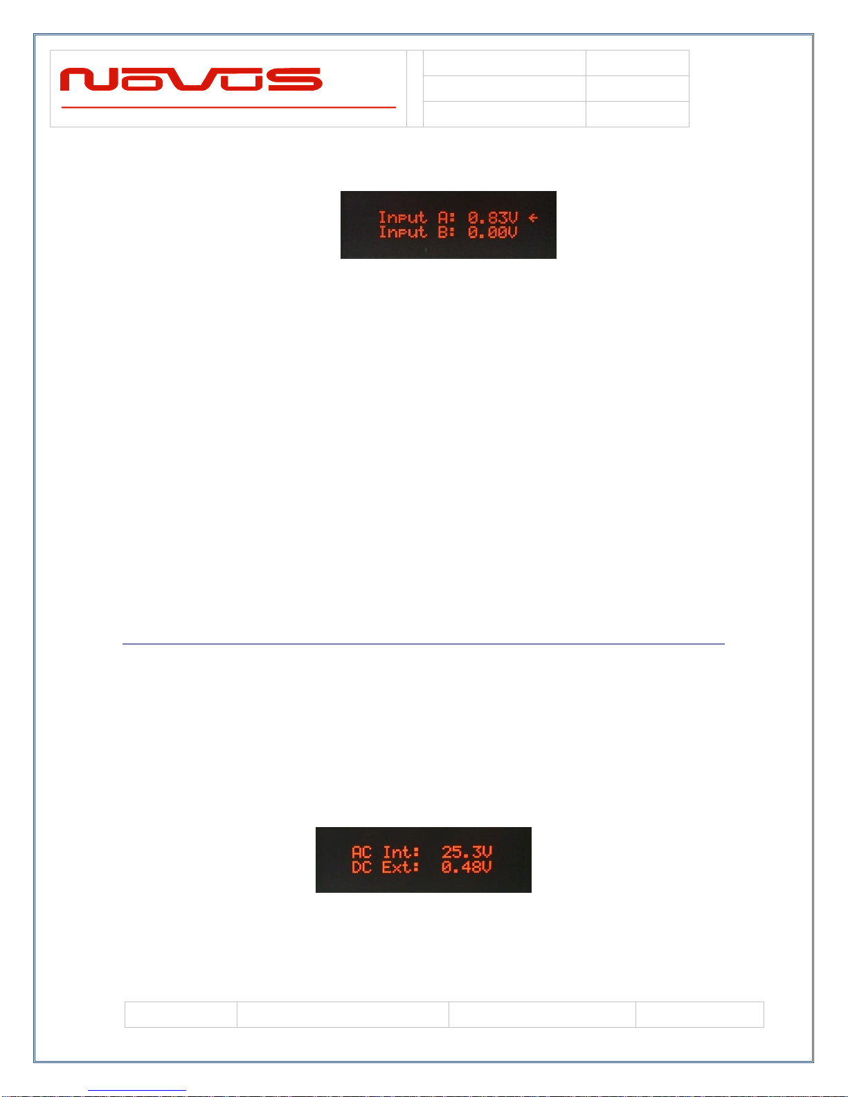
2.3 Input Status.................................................................................................7
2.4 Power Supply Status...................................................................................8
2.5 Attenuation................................................................................................10
2.6 Alert Threshold..........................................................................................11
2.7 Input Threshold .........................................................................................15
2.8 Input Select ...............................................................................................16
2.9 Latch Channel Values ...............................................................................17
2.9 Save Configuration....................................................................................17
2.10 Fault Status.............................................................................................18
2.11 Power Switch...........................................................................................19
2.12 RS232 DB9 Port......................................................................................20
3.0 Rear Panel....................................................................................................21
3.1 Channel Ouputs - BNC..............................................................................21
3.2 Status LEDs ..............................................................................................21
3.3 Signal Input A/B.........................................................................................22
3.4 24VDC Input..............................................................................................22
3.5 AC Input ....................................................................................................22
3.6 RS232 DB9 ...............................................................................................23
3.7 Optical Port................................................................................................24
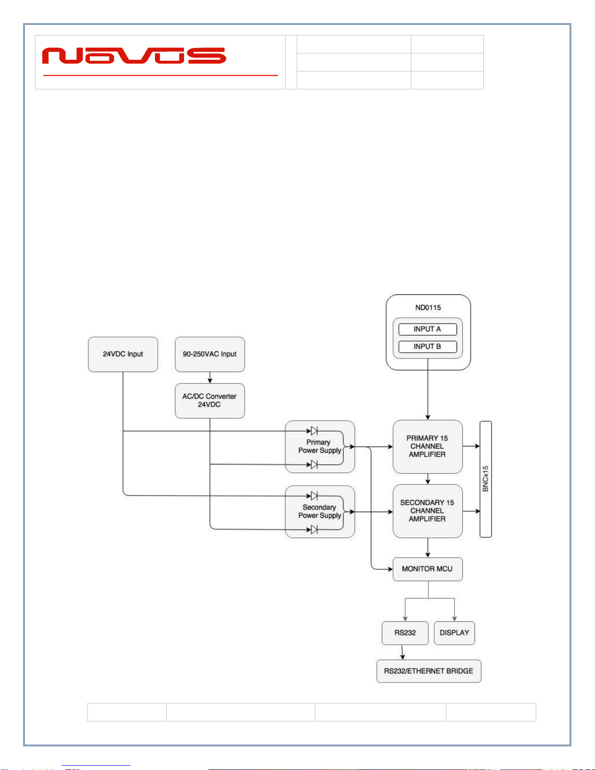
4.0 Functional Description ..................................................................................24
4.1 Bandwidth..................................................................................................25
4.2 Phase Noise..............................................................................................25
4.3 Outputs......................................................................................................27
4.4 Built in Test................................................................................................29
4.5 Power Supplies .........................................................................................29
4.6 Amplifier Test ............................................................................................30
5.0 Programming Guide (RS232 Port: Front and Rear)......................................32
5.1 RS232 Commands....................................................................................34
5.2 Status String ($GPNVS,1) Channel Measurements..................................39
5.3 Status String ($GPNVS,2) Power Supply Measurements .........................40
5.4 Status String ($GPNVS,3) Status Bytes....................................................41
5.5 Status Byte Key.........................................................................................42
5.6 Calibration Factors....................................................................................45
6.0 Specifications................................................................................................46
6.1 Technical specifications ............................................................................46
6.2 Environmental and Mechanical .................................................................46
7.0 LIMITED HARDWARE WARRANTY ............................................................47

USERS MANUAL
ND0115
REVISION NO.
H
DATE
6/01/17
Page #:
3 of 48
www.novuspower.com
1.0 Summary
The ND0115 is a 15/16 channel wide bandwidth distribution
amplifier. While primarily used for 10 MHz reference
distribution, it has a functional bandwidth from DC to 12 MHz,
but is filtered for the lowest phase noise 10MHz signal.
The amplifier is a low phase noise design to preserve the
integrity of the reference signal. All outputs are transient and
fault protected. The unit can be set up with 16 outputs and 1
input, or 15 outputs and dual redundant set of inputs: A and B.

USERS MANUAL
ND0115
REVISION NO.
H
DATE
6/01/17
Page #:
4 of 48
www.novuspower.com
The amplifier can also be optionally redundant. The redundancy
feature adds a second power supply and a second 15/16
channel amplifier PCB assembly. The dual input design
monitors the input signals and selects the active signal or the
prioritized signal. Each output channel is monitored against a
defined set of thresholds. If a fault is detected, monitoring will
report the fault serially, and if programmed, will cause the back-
up amplifier assembly to become the active amplifier. The two
15/16 channel amplifier assemblies are relay OR-ed in the
chassis avoiding the need for either splitters or complex cabling
to use the redundancy feature. The system connects to the
15/16 channels and all switching takes place internally as
required.
The unit features extensive reporting via the rear panel RS232
port - equipment status, output voltage on each channel and
redundancy status. By being able to monitor the output voltage,
the user can detect cabling issues that cause an impedance
change and replace cabling before it completely fails. Reporting
is also easily accessible via the front panel display.
Nominal power is global AC power but a DC power option can
be ordered that acts as the back-up power supply. Nominally 24
VDC, this port is used for power when AC power fails.
Switching between power sources is automatic and there is no
transient power outage at the equipment level. The primary
power supply is followed by low noise linear converter
assemblies. There will be one in a non-redundant configuration.
Each power supply supplies one of the amplifier assemblies.
To enhance versatility, the unit features a flexible output stage.
Each output amplifier can be configured as a linear amplifier,
CMOS output with ±20 mA drive or a very low impedance
sourcing output of over 100mA (ideal for driving pulsed outputs
in to 50 Ohms). This must be specified at the time of ordering.

USERS MANUAL
ND0115
REVISION NO.
H
DATE
6/01/17
Page #:
5 of 48
www.novuspower.com
2.0 Controls and Indicators – Front Panel
This section describes the functionality of the front panel
controls and indicators. Two buttons above the status LEDs
provide navigation through the menus.
In general, the NEXT button advances through the menus to
the next screen, while the SELECT button chooses between
the available values on a menu.
Menus that allow selectable adjustments are the Input
Threshold, Alert Threshold, and the Attenuation setting. To
adjust these values from the front panel, hold down both
buttons for two seconds until the value begins to flash. To
leave the menu with the new value, hold down both buttons
until the value is solid.
Screen Saver: After one hour, the OLED display will turn off
unless activated by a fault condition or by a user input, such as
pressing the NEXT or SELECT buttons.

USERS MANUAL
ND0115
REVISION NO.
H
DATE
6/01/17
Page #:
6 of 48
www.novuspower.com
2.1 Channel Status
The Channel Status can be determined by reading the actual
RMS value on the output of each stage. This is compared to a
threshold limit that is set by the user as a percentage variation
from a saved value. The default variation value is set at ±25%
from the current state of the amplifier, and is user
programmable in 5% increments from ±10% to ±60%.
The range of acceptable Channel Amplitude can be narrowed
around a connected balanced line, so that a Channel Status
below the Alert Threshold indicates a shorted line, while a
Channel Status above the Alert Threshold window indicates a
potential disconnected cable.
The threshold value at which a channel alert is triggered can be
programmed on the Alert Threshold screen, or programmed via
the RS232 port. Once set, the unit would continue to monitor
each channel and a deviation beyond the set limits would be
reported as a failure on the front panel and via RS232.
The Channel Status feature can quickly detect a cabling failure.
Any change in the load impedance will change the output
voltage with respect to the divider formed by the output
impedance of the amplifier and the load impedance. Failing
cables and connectors can be detected early.

USERS MANUAL
ND0115
REVISION NO.
H
DATE
6/01/17
Page #:
7 of 48
www.novuspower.com
The current threshold limits are displayed in addition to the
actual measured value. These values reflect the percentage
threshold defined in the Alert Threshold settings. If the output
value is too low to give a valid reading - the display will read
“LOW.”
The status is displayed on the front panel and is accessible
over the RS232 serial bus via DB9. Channel Status can be
cycled into view or can remain on a single channel. This
feature can be accessed via the NEXT button by advancing to
the Channel Status screen. To cycle through channels in
sequence, press the SELECT button.
2.2 Status LEDs
There are three status LEDs which provide a quick indication of
valid unit operation.
Alert LED: The Alert LED will illuminate flashing red to indicate
an input failure or a power supply failure. The Alert LED will
not flash RED if any valid input signal is present.
Oven LED (OCXO option only): The Oven LED will illuminate
red to indicate an Oven Failure.
Fault LED: The Fault LED will illuminate flashing red to
indicate a Channel Fault when any single channel is outside the
user defined threshold.
2.3 Input Status
The status of either input (A or B) can be monitored from the
Input Status screen. The input values are displayed in Vrms.
When an input is selected, an arrow appears next to the value
indicating that the source on that input is relayed to the output
channels.

USERS MANUAL
ND0115
REVISION NO.
H
DATE
6/01/17
Page #:
8 of 48
www.novuspower.com
If no input is present, or the input selection priority does not
have an input value which is above the input threshold, the
ALERT LED flashes red, and the screen indicates “Connect
Source.” The error is also noted in the fifth field of the $GPNVS
string, with the following values:
0 = At least one valid input is available, and is relayed to the
channel outputs.
1 = Input A is selected, and is below the input threshold.
2 = Input B is selected, and is below the input threshold.
For details on the status strings, see section 5.0 Programmer’s
Guide.
2.4 Power Supply Status
The Power Supply Status screen provides DC voltage values of
the two available power supply sources. The 90-250VAC input
is internally connected to an internal 24V AC-DC converter
which powers the internal supplies with 24V. This is diode
connected with the external 24VDC input, which can be used in
addition to, or in place of, the AC input.

USERS MANUAL
ND0115
REVISION NO.
H
DATE
6/01/17
Page #:
9 of 48
www.novuspower.com
The values of both DC supplies are measured internally to
validate connections. The measured values of the AC/DC
converter and the DC input are reported in the third and fourth
fields of the second $GPNVS status string.
For details on the status strings, see section 5.0 Programmer’s
Guide.
In addition to direct value measurements, each redundant
system has a Power Supply Status byte which is reported in the
third $GPNVS status string, in the seventh and eighth fields
respectively.
Any measurement of the power supply which results in an alert
condition will be reported in the power supply status byte.
0x80 = External AC not connected.
0x40 = External DC not connected.

USERS MANUAL
ND0115
REVISION NO.
H
DATE
6/01/17
Page #:
10 of 48
www.novuspower.com
Redundant power supplies operate on either the AC input or
DC input, and function independently. All functionality and
reporting for an individual power supply and amplifier is
independent of its redundant copy.
If a communications failure is reported, the backup system will
automatically switch to the redundant system.
2.5 Attenuation
The ND0115 is equipped with an internal 6-bit programmable
attenuator for each input channel. This feature can be used to
better match input signals if cabling differences exist. The
attenuation value is RS232 programmable with values 0x01 to
0x3F (1 –63), but is also added to the front panel in decimal
increments of 5 for convenient quick setting.
Pressing the SELECT button toggles the view between the A
and B input attenuation settings.
To adjust the attenuation from the front panel, hold the NEXT
and SELECT buttons down simultaneously for two seconds.
The percentage value will begin flashing. To increase the
value, press the SELECT button. To decrease the value, press
the NEXT button.
When the desired value is reached, press the NEXT and
SELECT button simultaneously to leave the settings mode.

USERS MANUAL
ND0115
REVISION NO.
H
DATE
6/01/17
Page #:
11 of 48
www.novuspower.com
Note: The 0dB point is approximately set to 45 or 0x2D on the
6-bit attenuator. This is equivalent to the 0% value on the
Attenuation menu. To fine-tune the attenuation for each
channel, program the attenuation between 1 and 63 (0x01 to
0x3F) via the front or rear panel RS232 port.
Setting the Attenuation Higher or Lower may move the output
measurements outside of the defined range of the Alert
Threshold. If Attenuation is set, be sure the Alert Threshold
values are optimized. This can be done simply by Latching the
values on the Latch Average Value Screen.
2.6 Alert Threshold
The Alert Threshold screen allows the user to adjust the
tolerance from the Reference Voltage which, if exceeded in
either direction, the output channels will report a fault status.
The default threshold value is set at ±25% from the current
state of the amplifier, and is user programmable in 5%
increments, from ±10% to ±60%.
Each channel has a Reference Voltage which can be set all at
once by latching the channels’ current value in the Latch
Channel Average Screen. Each channel’s reference voltage
can be set individually by writing the value serially with the
$SET command. After saving the current configuration on a

USERS MANUAL
ND0115
REVISION NO.
H
DATE
6/01/17
Page #:
12 of 48
www.novuspower.com
channel, any subsequent deviation on that channel which
exceeds the Alert Threshold percentage will trigger an alert.
Steps to ensure correct Alert configuration:
1. Connect source input(s) to channel A and/or B.
2. Connect distribution cabling to channels 1 through 16.
3. Set Alert Threshold to desired range.
4. Save current channel voltages with the Latch Channel
Values Screen.
5. Save current settings on the Save Configuration screen.
Note: Alert Threshold can be different for Input A and Input B,
allowing for variation in the input source. To accommodate
both inputs, set Alert threshold for Input A and Input B.

USERS MANUAL
ND0115
REVISION NO.
H
DATE
6/01/17
Page #:
13 of 48
www.novuspower.com
The Alert Threshold can be optimized so that a channel short or
an impedance change will cause an Alert.

USERS MANUAL
ND0115
REVISION NO.
H
DATE
6/01/17
Page #:
14 of 48
www.novuspower.com
Example:
The output of channel 1 is connected to a high impedance input
and reports 1.25Vrms at the output. The output of channel 2 is
connected to a 50Ohm terminated input, and reports 0.90Vrms
at the output.
Input A is connected to a ~0.95V 10MHz source.
Alert threshold for input A is set to +/-20%.
The current state is saved in the Save Configuration screen.
The Channel 1 alert will report when:
-The Channel 1 output is higher than 1.50Vrms
-The Channel 1 output is lower than 1.00Vrms
The Channel 2 Alert will report when:
-The Channel 2 output is higher than 1.08Vrms
-The Channel 2 output is lower than 0.72Vrms
Pressing the SELECT button toggles the view between the A
and B input Alert Threshold settings.
To adjust the Alert Threshold from the front panel, hold the
NEXT and SELECT buttons down simultaneously for two
seconds. The percentage value will begin flashing. To
increase the value, press the SELECT button. To decrease the
value, press the NEXT button.
When the desired value is reached, press the NEXT and
SELECT button simultaneously to leave the settings mode.
The Alert Threshold settings can be modified via the RS232
serial port with the $FLTTHRA and $FLTTHRB commands.
For details on the Alert Threshold, see section 5.0
Programmer’s Guide.

USERS MANUAL
ND0115
REVISION NO.
H
DATE
6/01/17
Page #:
15 of 48
www.novuspower.com
2.7 Input Threshold
The Input Threshold Screen allows the user to monitor and set
the threshold at which the input is regarded as invalid or
faulted.
The Input Threshold value is the absolute voltage (user
programmable between 0.1Vrms and 1Vrms) below which the
Input Fault will occur, and the Auto input select will consider the
signal invalid. The default minimum value is set to 0.3Vrms.
Pressing the SELECT button toggles the view between the A
and B Input Threshold settings.
To adjust the Input Threshold from the front panel, hold the
NEXT and SELECT buttons down simultaneously for two
seconds. The percentage value will begin flashing. To
increase the value, press the SELECT button. To decrease the
value, press the NEXT button.
When the desired value is reached, press the NEXT and
SELECT button simultaneously to leave the settings mode.
The Input Threshold settings can be modified via the RS232
serial port with the $INPTHRA and $ INPTHRB commands.
For details on the Input Threshold, see section 5.0
Programmer’s Guide.

USERS MANUAL
ND0115
REVISION NO.
H
DATE
6/01/17
Page #:
16 of 48
www.novuspower.com
2.8 Input Select
The Input Select screen allows the user to monitor and select the
Input Priority for inputs A and B. Pressing the SELECT button will
advance through the following settings:
-Input A select
-Input B select
-Auto Select (Priority A)
-Auto Select (Priority B)
Example: Input Select is set to Auto(A). Input A threshold is set
to 0.5Vrms. Input B threshold is set to 0.5Vrms.
Input A
Input B
Selection
0.90V
0.4V
A
0.90V
No Connection
A
No Connection
0.6V
B
0.4V
0.6V
B
No Connection
No Connection
Last Selected
The default setting is Auto (A). Input A select and Input B
select will select only A or B respectively.
Input Select Priority can also be programmed via the RS232
port with the $INP command:
-$INP=A: Input A select
-$INP=B: Input B select
-$INP=C: Auto Select (Priority A)
-$INP=D: Auto Select (Priority B)
For details on the Input Priority programming, see section 5.0
Programmer’s Guide.

USERS MANUAL
ND0115
REVISION NO.
H
DATE
6/01/17
Page #:
17 of 48
www.novuspower.com
2.9 Latch Channel Values
The Latch Channel Values Screen allows the user to save the
current channel output values for use as the Reference Value
for Alert settings.
A channel Alert is triggered when a channel output voltage
exceeds or falls below a percentage of the Reference Value.
This Reference Value is 1.10Vrms as a default, but can be set
by the user.
There are two ways to set the Reference Voltage. The RS232
serial port allows for setting an individual channel’s reference
voltage with the $SET command. The user can also use the
Latch Channel Values to take a snapshot of all current outputs
and use these as the reference values.
All channel Reference Values are with respect to the active
Input (A or B). If Input A and Input B are both present, this
allows for setting References on both inputs to accommodate
variation in amplitude between the two inputs.
2.9 Save Configuration
The Save Configuration screen allows the user to save the
current settings for Alert Threshold, Input Threshold,
Attenuation, Input Select, Reference Voltage and any other
settings that have been modified via the RS232 port.

USERS MANUAL
ND0115
REVISION NO.
H
DATE
6/01/17
Page #:
18 of 48
www.novuspower.com
To save the current settings, press the SELECT button twice.
The Save Configuration action is equivalent to the $SAVEFL
command on the serial port.
2.10 Fault Status
The Fault Status screen allows a quick overview of any channel
faults from the front panel. The total fault count is listed, as well
as a visual flashing indication of any channels that are beyond
the threshold values.
Press SELECT to advance to the System Fault Screen.

USERS MANUAL
ND0115
REVISION NO.
H
DATE
6/01/17
Page #:
19 of 48
www.novuspower.com
The System Fault Screen indicates any failures in the primary
system or the redundant backup system. All internal power
supplies are monitored (24V, +8V, -8V, 5V) on both the primary
and backup systems. A failure on one of these supplies will be
indicated with a “PS FAIL” fail warning for either system. A
communication failure would be indicated by a “Com FAIL”
indicator. Either of these fault statuses will result in the change
of the primary to the backup system. The individual statuses of
the internal power supplies are also available via the RS232
serial port.
The presence of a valid DC input voltage is indicated on this
screen as well as a valid AC power input. If either of these
supplies are not present, a “FL” indication will be shown next to
the appropriate input.
2.11 Power Switch
The front panel Power Switch controls AC Power input to the
unit. If the optional DC input is provided with 24V, or a valid
DC supply, the unit will operate. In other words, if the front
panel switch will not remove power if the optional DC input is
powered.
The AC and DC input option provides a redundant and
automatic backup source in the case of failure of either input.

USERS MANUAL
ND0115
REVISION NO.
H
DATE
6/01/17
Page #:
20 of 48
www.novuspower.com
2.12 RS232 DB9 Port
The front panel RS232 port allows convenient setup of the unit
in addition to the rear panel RS232 which may be connected to
a more permanent instrumentation setup.
The front panel RS232 port will respond to the same
commands as the rear panel and any changes made will be
reported on both serial ports. To receive the status strings on
the front panel port, the command $ACTFRP=1 is input. See
complete list of functionality in the Programmer’s Guide Section
5.0. The default Baudrate for the Front Panel Serial Port is
115200 baud, 8 bits, 1 stop bit, no parity.
RS232 Serial Port: Front Panel Pin Connections
Pin
Function
I/O
1
NC
2
Command Port TX
O
3
Command Port RX
I
4
NC
5
GND
GND
6
NC
7
NC
8
NC
9
NC
RS232 Programming Functionality is described in detail in Section 5.0.
Table of contents
Other Novus Amplifier manuals
Popular Amplifier manuals by other brands

RM
RM KL 351-24 Schematic diagram

Viking Electronics
Viking Electronics PA-2A How to configure

Krell Industries
Krell Industries Five-Channel Power Amplifier KAV-1500 Instructions for use

PRS Guitars
PRS Guitars Mark Tremonti MT15 user manual

Inter-m
Inter-m PA-935A Operation manual

bent audio
bent audio TAP user manual