Contents
Contents ...........................................................................................................................2
Safety................................................................................................................................3
Mounting ..........................................................................................................................4
Summary...........................................................................................................................5
The Time Base..............................................................................................................6
External PPS Locking ..................................................................................................8
The unit may be configured to lock to an external PPS signal. The signal must
conform to 3.3 V CMOS into a 1000 Ohm load. Rise time must be less than 10ns and
the pulse width must be greater than 10 ms.....................................................................8
PPS ...................................................................................................................................8
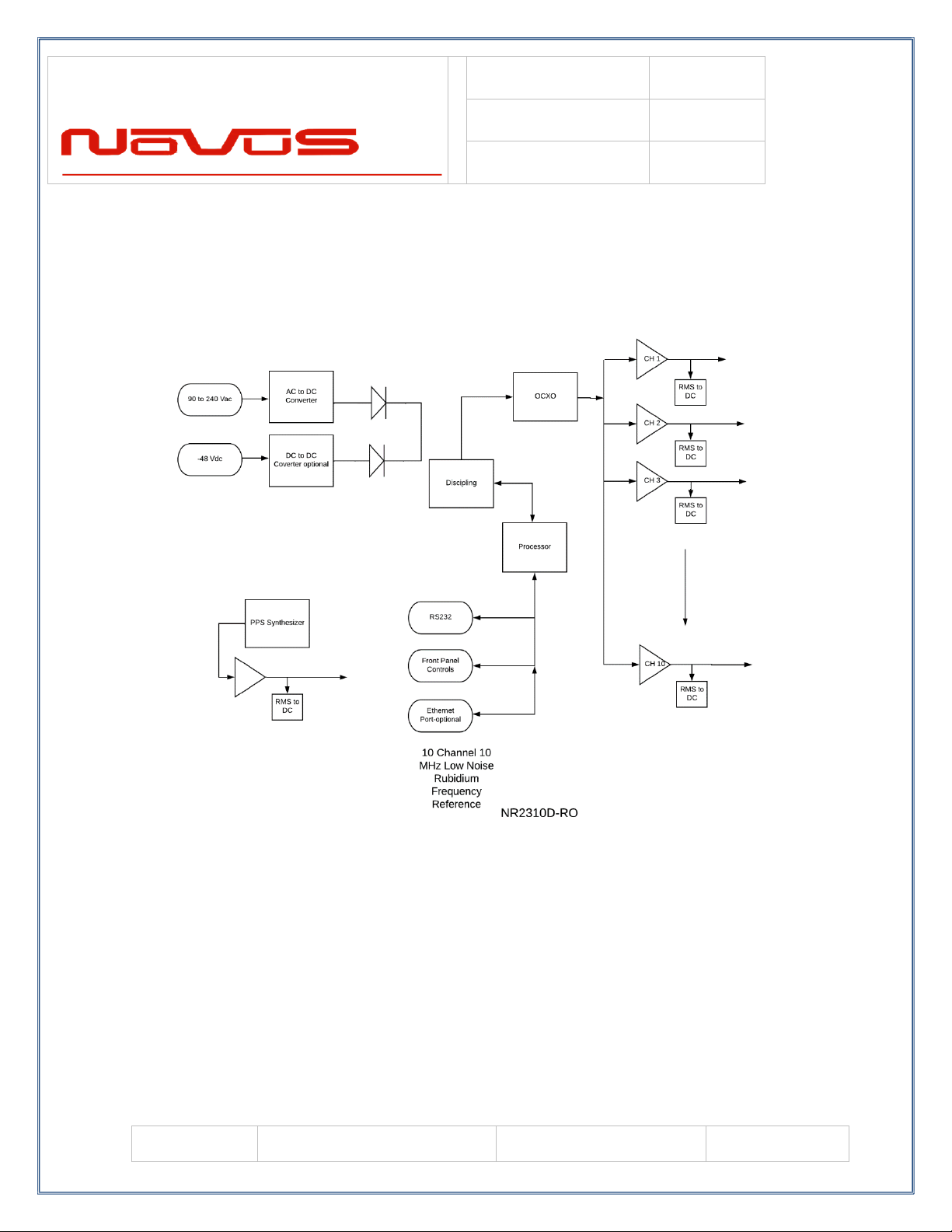
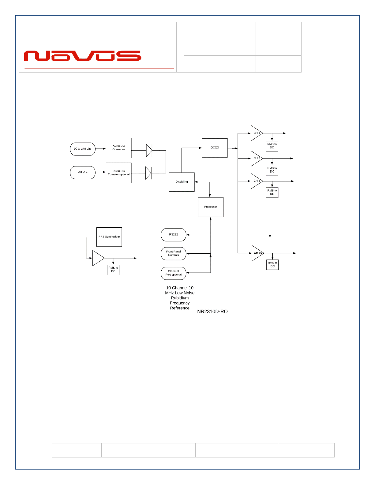
Base Unit Block Diagram...............................................................................................10
Phase Noise Performance...............................................................................................11
Controls and indicators...................................................................................................11
Channel Status- Front panel LED’s ...........................................................................12
Oven- LED front Panel...............................................................................................12
Digital Display (Optional)..........................................................................................12
RS232 NMEA / Alert –DB9 Male (Optional) .........................................................12
Rear Panel - Outputs.......................................................................................................13
Channel 1 through 10 output connectors –BNC or SMA .........................................14
Latch Channel Values ................................................................................................16
PPS –SMA (with GPS locking option) .....................................................................20
Alert –BNC-SMA......................................................................................................20
Power In......................................................................................................................20
Functional Description (Base NR2310D-RO) ...............................................................21
Outputs .......................................................................................................................21
Built-in Test....................................................................................................................21
Power Supplies...........................................................................................................21
Redundant power........................................................................................................22
Specifications .................................................................................................................23
Technical Specifications.............................................................................................23
Environmental and Mechanical..................................................................................24
Appendix C Novus Status and Control Strings..............................................................25
LIMITED HARDWARE WARRANTY .......................................................................26