Axxent AX-4120TS-D User manual

1
IMPORTANTSAFETY
PRECAUTIONS
Onrearsideoftheamplifieryoucanfinda
CAUTIONsymbol
Toreducetheriskofelectricshockdonot
removethecoverNouser-serviceable
partsinsideReferservicingtoqualified
personnel
!
INTRODUCTION
IMPORTANT FUNCTIONAL FEATURES
We are pleased that you have chosen one of these multichannel amplifiers from axxent. Please read the following
instructions for optimal results when using it.
Amplifiers of the axxent series with additional de-
signation „TS-D“ are network-compatible through
digital Dante/AES67 input and have isolated constant
voltage outputs for loudspeakers and loudspeaker
lines with transformer matching. The AX-4120TS-D
and AX-4240TS-D amplifiers can also be operated
with low impedance.
The AX-4120TS-D/4240TS-D amplifiers have four
discrete audio channels with a common power supp-
ly. All channels can be operated with low impedance
as well as with the constant voltage outputs 70 V
or 100 V. However, only optionally and not together.
Since you can use each channel as you wish with low
impedance OR high impedance (70/100 V), you can
meet almost all requirements in installations.
Operator‘s Manual AX-4120TS-D/AX-4240TS-D
®
Professional 4-channel power amplifiers
axxent e.K. · Technologiezentrum Herzbachtal · Zum Wartturm 15 · 63571 Gelnhausen
fon: +49-6051-9165584 · fax: 9165585 · mail@axxent.de · www.axxent.de
CONTROLS ON THE FRONT
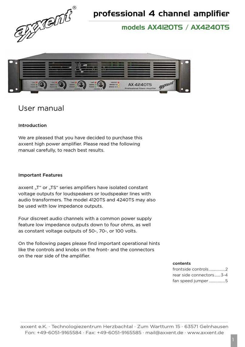
1: You will recognise four buttons on the left front. These
are the gain controls for the four channels of the am-
plifier. The gain controls are also commonly referred
to as volume controls. The gain controls can be ad-
justed with control knobs or, for safety, covered with
the blind plugs supplied with the amplifier. Of course,
the potentiometer knobs must be removed first.
2: Each gain control has three LED indicators - green,
green and red. The lower LED only indicates the
operation of the power amplifier - when switched on.
The middle green LED indicates that an input signal is
present. The upper red LED indicates that the maxi-
mum input level has been exceeded and that the
automatic limiter (signal limiter) is engaged.
3: To the right of the level controls you will find another
three-stage LED display, yellow, yellow, red. The two
yellow LEDs at the bottom indicate bridge operation of
channels 1+2 and 3+4. This so-called bridge mode serves
to double the power when the channels are operated in
low-impedance mode, i.e. with the AX-4120TS-D: 2x120
W result in about 240 watts. Realistically, you can expect
200 to 220 watts. With the AX-4240TS-D: 2x240 W
result in 480 watts, but again, please calculate only with
about 400 watts with the AX-4240TS-D. This power is
then available at 8 ohms. This will be described in more
detail later.
The upper red (Protect) LED indicates the self-protection
of the amplifier. When this LED is on, you will no longer
hear any sound, as the amplifier has switched o and
can only start up again after the fault has been rectified.
Please call the technician!
Additional controls on the front of the AX-4120TS ampli-
fier were deliberately omitted to prevent operating errors.
1
23
2
Operator‘s Manual AX-4120TS-D/AX-4240TS-D
®
Professional 4-channel power amplifiers
axxent e.K. · Technologiezentrum Herzbachtal · Zum Wartturm 15 · 63571 Gelnhausen
fon: +49-6051-9165584 · fax: 9165585 · mail@axxent.de · www.axxent.de
REAR OF THE AMPLIFIER (AX-4120TS-D AND AX-4240TS-D IDENTICAL)
1: On the far left you can see the large, sturdy mains
switch at the top. This is a rocker switch - in the upper
position on and the lower position o.
2: Below the mains switch is the mains input socket
according to the international IEC standard. Delibe-
rately, no permanently connected mains cable was
used here, so that the mains cable can be easily re
moved in case of a possible malfunction of the ampli-
fier. The mains cable is included with the amplifier.
The mains input socket also includes a fuse holder.
If the amplifier malfunctions, i.e. if you have switched
on the amplifier and the green „Power“ LEDs do not
light up, the mains fuse may be defective. Please call
the technician and, if possible, do not replace it your-
self. Just in case: The mains fuse is 6.3 A (8 A for the
AX4240TS-D), slow-blow and has the dimensions
5x20 mm.
3: Digital Dante/AES67 input: To the right of the switch
and the mains input socket you will see an RJ45
socket. This is the input socket for a digital Dante/
AES67 signal. This digital input is fully compatible with
the usual Dante audio standard. In case of a digital
malfunction, there is a recessed reset button above the
RJ45 socket. This resets the set digital parameters
to the default settings. To the right of the RJ45 socket
are the digital/analogue selector switches. Here you
can select for each of the four amplifier channels
whether you want to use the digital or the analogue
input. Below the selector switch you will see a push-
button switch for selecting the digital input level. The
default setting is 0 dBu. In the depressed position
-9 dBu (see page 4)
4: Analogue input sockets of the amplifier: The analogue
input sockets of the amplifier are designed as 3-pole
XLR sockets. These can be found on the lower side,
Input 4, Input 3, Input 2, Input 1. These inputs are
electronically balanced and have an input impedance
of 20 kOhm. Any standard microphone cable, desi-
gned according to international standards, can easily
be used here for connection to mixing consoles or
audio distribution units.
5: Between the connection Input 4, Input 3, and Input 2,
Input 1, there is a recessed pressure switch each.
These serve to activate the bridge mode of the respec-
tive input pair if required.
6: Output sockets of the amplifier: You see two 10-
pole, green terminal blocks. These are assigned with
the constant voltage outputs 70 and100 V as well as
with the low-impedance connections. In European
countries, 100 V operation is common. For constant
voltage operation itself, axxent has a manual „Basics
of 100 V loudspeaker systems“. The connections are
designed as screw-terminal connections. As the screw
terminals are quite tight for safety, please use a small
tool (screwdriver or similar) to pull them out. Then you
can simply attach your stripped connection cables to
the terminals with a small slotted screwdriver.
7: Fan operation: The AX-4120TS-D/4240TS-D amplifiers
use a two-stage fan for rear-to-front airflow. The speed
of the fan is controlled by the temperature of the
internal transistor heat sinks. During high-performance
operation, the fan switches to level 2.
1
2
3
4 4
5 5
6 6
7
3
Operator‘s Manual AX-4120TS-D/AX-4240TS-D
®
Professional 4-channel power amplifiers
axxent e.K. · Technologiezentrum Herzbachtal · Zum Wartturm 15 · 63571 Gelnhausen
fon: +49-6051-9165584 · fax: 9165585 · mail@axxent.de · www.axxent.de
Bridge mode:
Bridge mode refers to the low impedance outputs of the
amplifier. In single-channel mode, the AX-4120TS-D ampli-
fier has a power of 120 W RMS. If you need more power,
you can, for example, operate channel 1+2 in bridge mode
and thus combine the power, i.e. mathematically double
it. As described above, you have to accept a power cut of
about 10 percent.
Below is an example of the digital signal connection using Dante software.
So you have a maximum of 220 watts into 8 ohms. This
applies analogously to the AX-4240TS-D with 240 W in
single-channel operation.
Please note that in bridge mode you cannot use these
outputs for 70/100 V operation.
CE-Konformitätserklärung
PRODUCTTYPE: axxent AX4120TS-D/AX4240TS-D
TYPE OF PRODUCT: Mains-connected audio amplifier for
professional purposes
We hereby declare on our sole responsibility that this com-
plies with the requirements set out in the Council Directives
on the approximation of the laws of the member states of the
European Community relating to the Electromagnetic compa-
tibility (EMC) - 2014/30/EU and in the Low Voltage Directive
2014/35/EU are fixed.
The following standards were used to assess the products with
regard to EMC interference radiation: EN55032:2015, Class B;
EN61000-3-2, -3. For compatibility, the following standards
were used: EN55024:2010+A1:2015; EN61000-4-2, 3,4,5,6,8,11.
The following standard was used to assess the products with
regard to the Low Voltage Directive: EN60950-1 of 2006 +
A11+A12+A2.
Furthermore, the product described above complies with
the provisions of Directive 2011/65/EU of the European
Parliament and of the Council on the restriction of the use
of certain hazardous substances in electrical and electronic
equipment.
axxent e.K., 63571 Gelnhausen
Owner: Josef Becker
DATE: 08-29-2023
4
Operator‘s Manual AX-4120TS-D/AX-4240TS-D
®
Professional 4-channel power amplifiers
axxent e.K. · Technologiezentrum Herzbachtal · Zum Wartturm 15 · 63571 Gelnhausen
fon: +49-6051-9165584 · fax: 9165585 · mail@axxent.de · www.axxent.de
This manual suits for next models
1
Other Axxent Amplifier manuals

Axxent
Axxent ISV 1090 User manual

Axxent
Axxent AMV-7240 User manual

Axxent
Axxent AMV-7240 MKII User manual

Axxent
Axxent AX2150S User manual

Axxent
Axxent CLP2090 User manual

Axxent
Axxent AX1121TS User manual

Axxent
Axxent AX2120TS User manual

Axxent
Axxent GPX 2500 User manual

Axxent
Axxent AX4120TS User manual

Axxent
Axxent AX-1121TS User manual