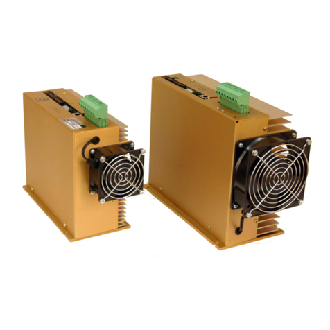
Glentek SMA8115 Installation and operating instructions

OPERATION
&
SERVICE MANUAL
Model SMA8115
Model SMA8215
Model SMA8315
Brushless Amplifier System


Glentek Inc., 208 Standard Street, El Segundo, California 90245, U.S.A. (310) 322
-
3026
3
TABLE OF CONTENTS
INTRODUCTION...................................................................................................6
CHAPTER ONE: DESCRIPTION, FEATURES AND SPECIFICATIONS
1.1 DESCRIPTION........................................................................................................ 7
1.2 FEATURES ............................................................................................................ 8
1.2.1 Single Amplifier Module (SMA8X15-1)..................................................... 8
1.2.2 Multi-Axis Power Supply (GP8600-70)..................................................... 9
1.3 SPECIFICATIONS.................................................................................................... 9
1.3.1 Single Amplifier Module (SMA8X15-1)..................................................... 9
1.3.1.1 Input and Output Power.................................................................. 9
1.3.1.2 Signal Inputs .................................................................................. 9
1.3.1.3 Digital Inputs ................................................................................ 10
1.3.1.4 System......................................................................................... 10
1.3.1.5 Outputs......................................................................................... 10
1.3.2 Multi-Axis Power Supply........................................................................ 10
1.3.2.1 Input and Output Power................................................................ 10
1.3.3 Mechanical............................................................................................ 10
CHAPTER TWO: THEORY OF OPERATION
2.1 INTRODUCTION.................................................................................................... 11
2.2 DRIVING DC SERVO MOTORS.............................................................................. 11
2.3 SERVO LOOPS .................................................................................................... 11
2.4 BRUSHED MOTORS VS BRUSHLESS MOTORS ........................................................ 12
2.5 SINUSOIDAL VS TRAPEZOIDAL .............................................................................. 13
2.6 THE ADVANTAGES AND DISADVANTAGES OF ATRAPEZOIDAL AMPLIFIER SYSTEM .... 14
2.7 CURRENT MODE VS VELOCITY MODE................................................................... 14
2.8 TACHOMETER (VELOCITY MODE) FEEDBACK OPTIONS........................................... 14
2.9 COMMUTATION USING A RESOLVER ..................................................................... 15
2.10 CURRENT MODE IN SINE/RESOLVER OR TRAPEZOIDAL AMPLIFIER VS TWO/THREE
PHASE INPUT CURRENT MODE AMPLIFIER ............................................................ 15
2.11 PROTECTION CIRCUITS........................................................................................ 15
CHAPTER THREE: MODEL NUMBERING
3.1 INTRODUCTION.................................................................................................... 16
3.2 SINGLE AMPLIFIER MODULES............................................................................... 16
3.2.1 Trapezoidal Mode.................................................................................. 16
3.2.2 Sine/Resolver Mode .............................................................................. 17
3.2.3 Two/Three Phase Input Current Mode................................................... 18
3.3MULTI AXIS AMPLIFIER SYSTEM ........................................................................... 19
CHAPTER FOUR: INSTALLATION
4.1 INTRODUCTION.................................................................................................... 20
4.2 MOUNTING.......................................................................................................... 20
4.3 WIRING .............................................................................................................. 20
4.3.1 RFI/EMI and Wiring Technique.............................................................. 20
4.3.2 Wire Size and Type ............................................................................... 20
4.3.3 Connector Size and Type ...................................................................... 21
4.3.3.1 The Signal Connector................................................................... 21
4.3.3.2 The Power Connector -J2 of Main Amplifier ................................ 21
4.4 SINGLE AMPLIFIER MODULE CONNECTIONS (SMA8X15-1).................................... 22
4.4.1 Buss and Motor Connections -J2.......................................................... 22
4.4.2 Signal Connections for the Trap. and Sine/Resolver Mode -J1............. 22
4.4.3 Signal Connections for the 2/3 Phase Current Mode Amplifier............... 23

Glentek Inc., 208 Standard Street, El Segundo, California 90245, U.S.A. (310) 322
-
3026
4
SMA8115, SMA8215, and SMA8315 MANUAL
4.4.4 Signal Connections for the Trapezoidal Mode Pre-amp......................... 23
4.4.5 Signal Connections for the Sine/Resolver Mode Pre-amp...................... 24
4.5MULTI AXIS POWER SUPPLY CONNECTIONS (GP8600-70) .................................... 24
CHAPTER FIVE: CONFIGURATION
5.1 INTRODUCTION.................................................................................................... 25
5.2 LOGIC INPUT CONFIGURATION.............................................................................. 25
5.3 TRAPEZOIDAL MODE AMPLIFIER CONFIGURATION .................................................. 25
5.3.1 +15V/+5V Logic Level Configuration...................................................... 25
5.3.2 Standard Configuration.......................................................................... 26
5.3.3 Integrator Configuration......................................................................... 26
5.3.4 Hall-Sensor Configuration...................................................................... 26
5.3.5 Motor Reverse Configuration................................................................. 26
5.3.6 Simulated Tach -Disable Configuration................................................. 26
5.3.7 Simulated Tach -Reverse Configuration ............................................... 26
5.3.8 Simulated Tach -Speed Configuration .................................................. 26
5.4 SINE/RESOLVER MODE AMPLIFIER CONFIGURATION .............................................. 27
5.4.1 +15V/+5V Logic Level Configuration...................................................... 27
5.4.2 Standard Configuration.......................................................................... 27
5.4.3 Encoder Output Resolution Configuration.............................................. 28
5.4.4 Motor Pole Configuration....................................................................... 29
5.5 TWO/THREE PHASE INPUT CURRENT MODE AMPLIFIER CONFIGURATION ................ 29
5.5.1 +15V/+5V Logic Level Configuration...................................................... 29
5.5.2 Standard Configuration.......................................................................... 29
CHAPTER SIX: START UP AND CALIBRATION
6.1INTRODUCTION.................................................................................................... 30
6.2 INITIAL START UP................................................................................................ 30
6.3 TRAPEZOIDAL MODE AMPLIFIER CALIBRATION....................................................... 30
6.3.1 Velocity and Simulated Velocity Mode Calibration Procedure................ 30
6.3.2 Current Mode Calibration Procedure...................................................... 32
6.4 SINE/RESOLVER MODE AMPLIFIER CALIBRATION ................................................... 32
6.4.1 Velocity Mode Calibration Procedure..................................................... 32
6.4.2 Current Mode Calibration Procedure...................................................... 33
6.5 TWO/THREE PHASE INPUT CURRENT MODE AMPLIFIERCALIBRATION ..................... 34
6.5.1 Two Phase Input Current Mode Calibration Procedure.......................... 34
6.5.2 Three Phase Input Current Mode Calibration Procedure........................ 34
6.6 CALIBRATION SETUP RECORD.............................................................................. 35
6.7 RESOLVER ALIGNMENT ....................................................................................... 35
6.7.1 Resolver Alignment Procedure .............................................................. 36
CHAPTER SEVEN: MAINTENANCE, REPAIR AND WARRANTY
7.1 MAINTENANCE..................................................................................................... 38
7.2 AMPLIFIER FAULTS .............................................................................................. 38
7.2.1 Table of Fault LED Conditions............................................................... 38
7.2.2 Under Voltage Fault............................................................................... 38
7.2.3 Motor Over Temp Fault.......................................................................... 38
7.2.4 High Speed Electronic Circuit Breaker (HS/ECB) Fault.......................... 39
7.2.5 Low Speed Electronic Circuit Breaker (LS/ECB) Fault........................... 39
7.2.6 Over Temp Fault.................................................................................... 39
7.2.7 Over Voltage Fault................................................................................. 39
7.2.8 Resetting A Fault................................................................................... 39
7.3 AMPLIFIER FAILURE............................................................................................. 39
7.4 FACTORY REPAIR................................................................................................ 40
7.5 WARRANTY......................................................................................................... 40

Glentek Inc., 208 Standard Street, El Segundo, California 90245, U.S.A. (310) 322
-
3026
5
APPENDIX A: AMPLIFIER DRAWINGS
SMA8015 BRUSHLESS POWER BOARD INSTALLATION SCHEMATIC (8015-2030).............42
SMA8015 BRUSHLESS POWER BOARD ASSEMBLY DRAWING (8015-2031).....................43
SMA8115-1 TRAPEZOIDAL SINGLE AMPLIFIER MODULE INSTALLATION(8015-1032).........44
SMA8215-1 SINE/RESOLVERSINGLE AMPLIFIER MODULE INSTALLATION(8015-1033).....45
SMA8315-1 TWO/THREE PHASE SINGLE AMPLIFIER MODULE INSTALLATION(8015-1034)46
SMA8X15-2A-2 2-AXIS INSTALLATION DRAWING (8015-1033).......................................47
SMA8X15-4A-4 4-AXIS INSTALLATION DRAWING (8015-1032).......................................48
APPENDIX B: MULTI-AXIS POWER SUPPLY
GP8600-70 60A POWER SUPPLY ASSEMBLY DRAWING (8600-7030)............................50
APPENDIX C: PERSONALITY MODULE (PRE-AMP)
SMA8115 TRAPEZOIDAL MODE INSTALLATION SCHEMATIC (8000-1130) ........................52
SMA8115 TRAPEZOIDAL MODE ASSEMBLY DRAWING (8000-1131)................................53
SMA8215 SINE/RESOLVER MODE INSTALLATION SCHEMATIC (8000-1430 PAGE 1).........54
SMA8215 SINE/RESOLVER MODE INSTALLATION SCHEMATIC (8000-1430 PAGE 2).........55
SMA8215 SINE/RESOLVER MODE ASSEMBLY DRAWING (8000-1431)............................56
SMA8215 SINE/RESOLVER MODE INSTALLATION SCHEMATIC (8000-2230 PAGE 1).........57
SMA8215 SINE/RESOLVER MODE INSTALLATION SCHEMATIC (8000-2230 PAGE 2).........58
SMA8215 SINE/RESOLVER MODE ASSEMBLY DRAWING (8000-2202)............................59
SMA8315 2Ø/3Ø CURRENT MODE INSTALLATION SCHEMATIC (8000-1330)...................60
SMA8315 2Ø/3Ø CURRENT MODE ASSEMBLY DRAWING (8000-1331)..........................61
APPENDIX D: EUROPEAN UNION EMC DIRECTIVES
ELECTROMAGNETIC COMPATIBILITY GUIDLINES FOR MACHINE DESIGN ............................63
CE CERTIFICATION ......................................................................................................68
TABLE OF CONTENTS

Glentek Inc., 208 Standard Street, El Segundo, California 90245, U.S.A. (310) 322
-
3026
6
SMA8115, SMA8215, and SMA8315 MANUAL
Introduction
Glentek's brushless DC motors and amplifiers offer the ultimate in low maintenance and high
performance motion-control. Glentek offers a full line of matched motors and amplifiers to meet
virtually every motion-control application.
This manual provides all the technical information necessary to install, configure, operate, and
maintain our TORQUE-SWITCH™series, brushless servo-motor amplifiers, models SMA8115,
SMA8215, SMA8315, and the high power versions, models SMA8115HP, SMA8215HP, SMA8315HP.
These amplifiers combine the economy of trapezoidal drive current or the high performance of
sinusoidal motor current with the efficiency of pulse-width modulation (PWM).
We suggest that you take the time to read this manual from cover-to-cover before attempting
to work with these amplifiers for the first time. If at any time you have questions not addressed in
this manual, or have any special requirements, please feel free to call and discuss them with a
Glentek applications engineer. We are happy to provide both off-the-shelf and custom products. With
over three decades in the servo-motor/amplifier business, we have a vast pool of applications
knowledge waiting to assist you.
Thank you for selecting Glentek for your motion-control needs. It is our goal to save you time and
money, and to provide you with a superior product.

Glentek Inc., 208 Standard Street, El Segundo, California 90245, U.S.A. (310) 322
-
3026
7
Chapter One: Description, Features and Specifications
1.1 Description:
This brushless amplifier system has been designed to offer you, our customer, a large degree of flexibility and
customization with a standard, in stock product. Each amplifier module consists of a standard power output board
with one of our three types of personality modules mounted on it. (To help you understand the various brushless
amplifier and motor system combinations and their respective advantages and disadvantages, please refer to chapter
two of this manual which describes the theory of operation). Following is a brief description of these three personality
modules and their mode(s) of operation:
Trapezoidal Mode (SMA8115/SMA8115HP) -In this mode of operation, which is also commonly referred to
as six step, the brushless motor is commutated by hall sensors or an encoder which contains these
commutation signals. This personality module can be configured for the following three different types of
operation:
VELOCITY MODE -In this mode of operation, a velocity signal from a brushless or brush type
tachometer is used to close a velocity loop in the amplifier. Please see section 2.3, 2.7, 2.8 of this
manual for more detailed information.
SIMULATED VELOCITY MODE -In this mode of operation, a circuit on the personality module looks at
the hall sensors and generates a simulated velocity signal which is used to close a velocity loop in the
amplifier. This mode of operation offers an extremely cost effective velocity mode system for medium to
high velocity applications. Please see section 2.6 of this manual for more detailed information.
CURRENT MODE -In this mode of operation, which is also commonly referred to as torque mode, a
current in the motor is produced which is directly proportional to the input signal. Please see section 2.2,
2.5, 2.7 of this manual for more detailed information.
Sine/Resolver Mode (SMA8215/SMA8215HP) -In this mode of operation, a brushless motor with an integral
resolver is required. The personality module contains a resolver to digital converter which provides the
positional information to the amplifier that is required to commutate the motor. This positional information is
also used by the personality module to emulate a quadrature encoder output. This personality module can be
configured for the following two different types of operation:
VELOCITY MODE -In this mode of operation, the personality module generates a tachometer signal
which is used to close a velocity loop in the amplifier. Please see section 2.3, 2.5, 2.8 of this manual for
more detailed information.
CURRENT MODE -In this mode of operation, which is also commonly referred to as torque mode, sine
wave currents in the motor are produced that are directly proportional to the input signal. Please see
section 2.5, 2.7, 2.9 of this manual for more detailed information.
Two/Three Phase Input Current Mode (SMA8315/SMA8315HP) -In the two phase current mode, the
amplifier generates three sine wave currents that are proportional to two input signals. This third command is
generated on the personality module as the negative sum of the other two signals. In the three phase current
mode, the amplifier generates three sine wave currents that are proportional to three input signals. Please
see section 2.5, 2.9 of this manual for more detailed information.
These brushless amplifiers come with all industry standard inputs such as +/-limit, fault output, etc. They are
available in the following types of configurations:
As amplifier modules where you supply the DC Buss voltage, cooling fan(s), fusing and shunt regulator.
Please see section 1.2.1 for more detailed information.
For multi-axis applications, the multi-axis baseplate power supply can supply
DC power, cooling fans, zero crossing solid state relays, fusing and a shunt
regulator for up to 4axis or 60 amperes continuous. Please see section 1.2.3 for
more detailed information.
CHAPTER 1: DESCRIPTION, FEATURES AND SPECIFICATIONS
Glentek Inc., 208 Standard Street, El Segundo, California 90245, U.S.A. (310) 322
-
3026
8
SMA8115, SMA8215, and SMA8315 MANUAL
1.2 Features:
1.2.1 Single Amplifier Module (SMA8X15-1):
•Ergonomic design: Easy access to connections, adjustments, and test points.
•Wide operating 70-340VDC.
buss voltage:
•Complete isolation: Complete isolation from input to output.
•Dual signal inputs: Two single-ended or one differential. Both single-ended inputs may be
used simultaneously. All inputs have up to 15,000 A/V gain, and all inputs
will accept ±13VDC.
•Dual mode operation: The standard amplifier may be configured for velocity (RPM) control or
(8115 & 8215 only) current (torque) control.
•Current limit: Maximum motor current is adjustable.
•Silent operation: Carrier frequency is 20KHz.
•Short circuit protection: Complete short circuit and ground fault protection.
•LED diagnostics: Red LED(S) illuminate to display various fault conditions and a green LED
illuminates to indicate normal operating conditions.
•Encoder emulation: Encoder emulation comes standard with line driver outputs, quadrature and
(8215 only) zero index.
•Frequency response: 750 Hz minimum.
(Velocity Loop)
•Frequency response: 2 KHz minimum.
(Current Loop)
•Digital limit/enable Three separate logic inputs can stop the motor in either or both directions.
Inputs: Inputs may be configured for active-high or active-low, pull-up or pull-down
termination, and a 0 to +5V or 0 to +15V range.
•Pseudo tach. option: For medium and high-speed, unidirectional or bidirectional applications, an
(8115 only) option allows the hall sensor inputs to produce a simulated tachometer
voltage thus eliminating the need for an external tachometer.
•Encoder outputs: Incremental (quadrature) position outputs with separate index.
(8215 only) 19 different encoder counts, from 125 to 4096 counts/revolution, are
available. Differential line-driver output devices sink and source 40mA.
•Tachometer output: DC output proportional to motor RPM.
(8115 & 8215 only)
•Fault input/output: Open-collector output goes low in the event of a fault. This input is
configured so that externally forcing this output low will inhibit the amplifier.
This allows all fault outputs in a multi-axis system to be connected together
(wire-ORed) to shut down all amplifiers should any amplifier have a fault.
•Manual and external Push button and a separate input is provided to reset the amplifier after
fault reset: a fault.
•High-Speed Electronic Instantly shuts down the amplifier in the event of a short across the motor
Circuit Breaker leads or a ground fault condition.
(HS/ECB): (i.e. amplifier exceeds 80A for 10 microseconds)
•Low-Speed Electronic Shuts down the amplifier if the amplifier is operated above the maximum
Circuit Breaker continuous current rating (i.e.15A for standard 120VAC, 10A for standard
(LS/ECB): 240VAC; 20A for High Power 120VAC and 15A for High Power 240VAC)
for a pre-determined period (i.e. 3 seconds).

Glentek Inc., 208 Standard Street, El Segundo, California 90245, U.S.A. (310) 322
-
3026
9
•Over/under voltage These circuits constantly monitor the amplifier power-supply voltages, and
and over temperature: the motor and amplifier-heatsink temperatures. They will shut down the
amplifier in the event of any out-of-specification condition. (The overvoltage
protection circuit is set to turn on at +250VDC for 120VAC line input and
+450VDC for 240VAC line input.)
•Multi-axis chassis: Up to four amplifier modules may be mounted on a single baseplate. Multi-
axis baseplates include a DC power supply, cooling fan(s) and wiring for
each respective amplifier module.
1.2.2 Multi-Axis Power Supply (GP8600-7000):
•Power supply for 2 to 4axis amplifier baseplate.
•Line operated AC power operation: Fused single or three phase AC inputs with a solid state zero-crossing
switch which limits in-rush current at turn-on. No power isolation transformer is required.
•Fused regen clamp circuit (shunt regulator) with LED indicator and 95W internal load resistor bank bleeds
off excess DC Buss voltage when decelerating a large load inertia. Additional regen resistorscan be
connected externally.
•Bridge rectifier(s) and filter capacitor.
•Cooling fans.
1.3 Specifications:
This section contains the specifications for the brushless trapezoidal, sine/resolver and two or three phase
input current mode D.C. Servo Amplifiers. These specifications also include power supplies for the amplifiers.
NOTE: All data in this section is based on the following ambient conditions: 120oF (50oC) maximum.
Forced air cooling.
1.3.1 Single Amplifier Module (SMA8X15-1):
The amplifier module(s) require an external DC power supply which must include a bridge rectifier, buss
capacitor, solid-state relay and shunt regulator. Forced air cooling is required to meet the maximum
power ratings specified below.
1.3.1.1 Input and Output Power:
1.3.1.2 Signal Inputs:
CHAPTER 1: DESCRIPTION, FEATURES AND SPECIFICATIONS
Input Power/
Buss Voltage(B+) Output Power
(current)
Standard
R.M.S. Peak R.M.S. Peak
120VAC/170VDC 15A 25A20A 40A
240VAC/340VDC 10A 25A 15A 35A
High Power
Amplifier
Model Signal Input Maximum
Voltage
(VDC)
Minimum
Impedance
Ù
Velocity Gain
Amp./Volt Current Gain
Amp./Volt
8115/8215 Differential 13 10,000 15,000(min.) 0-5
8115/8215 Single-ended ±13 10,000 15,000(min.) 0-5
8315 2/3phase input ±13 10,000 0-5

Glentek Inc., 208 Standard Street, El Segundo, California 90245, U.S.A. (310) 322
-
3026
10
SMA8115, SMA8215, and SMA8315 MANUAL
1.3.1.3 Digital Inputs:
•± Limit, Inhibit & Reset: 40/-0.5V max. Terminated by 10,000 ohms.
•Fault (as input): 40/-0.5V max. Terminated by 10,000 ohms.
•Typical for all digital inputs: Digital inputs have hysteresis with thresholds at 1/3 and 2/3 of +5V
or +15Vdepending on range select jumper.
1.3.1.4 System:
•Drift offset over temperature reference to input: 0.01mV/ oC max.
•Frequency response (Velocity loop): 750Hz min.
•Frequency response (Current loop): 2KHz min.
•Dead band: None.
•Form factor: 1.01.
1.3.1.5 Outputs:
•Fault (as output): Active low. Open-collector output can sink 500mA max.
•Abs. motor current: 10A/V.
•Tachometer : 1000Ùsource impedance, a high input impedance meter must be used
(1MÙ/volt). Maximum Tachometer output voltage for 12 bit = 0.5V/KRPM,
14 bit = 2V/KRPM.
•Encoder outputs: Standard TTL levels with 20mA sink or source capability.
(8215 only)
1.3.2Multi Axis Power Supply:
The multi-axis power supply contains all items listed under 1.2.3.
1.3.2.1 Input and Output Power:
•Input Power (Buss, B+, Control Power, Fans): 120/240VAC.
•Buss Voltage, B+: 170/340VDC.
•Output Power: 60A continuous
1.3.3Mechanical:
Model L x W x H
(inches) Weight
(lbs)
SMA8X15-1(Single Amplifier Module) 7.125 x 1.38 x 4.53 1.28
SMA8X15-2A-2 (2 Axis Amplifier System) 9.00 x 10.50 x 7.70 9.36
SMA8X15-4A-4 (4 Axis Amplifier System) 13.00 x 10.50 x 7.70 15.12

Glentek Inc., 208 Standard Street, El Segundo, California 90245, U.S.A. (310) 322
-
3026
11
Chapter Two: Theory of Operation
2.1 Introduction:
This chapter contains the basic control theory of how brush-type and brushless servo motors and amplifiers
operate. It also compares and contrasts the advantages and disadvantages of brushless and brush type
motors and amplifiers to help you select which is best suited for your application. The following is a summary
of the topics:
•The theory behind an amplifer driving DC servo-motors.
•A comparison between brush-type and brushless motors.
•A comparison between trapezoidal mode and sinusoidal mode amplifier system.
•The advantages and disadvantages of trapezoidal mode amplifier systems.
•A comparasion between velocity mode and current mode.
•Various kinds of velocity feedback.
•Commutation using resolver.
•Current mode in sine/resolver or trapezoidal amplifier vs two/three phase input current amplifier.
•Protection circuits.
2.2 Driving DC Servo-Motors:
The torque of any DC motor is proportional to motor current: the stronger the magnetic field, the stronger the
pull. Motor current may be controlled in two ways: linear and PWM (Pulse-Width Modulation). Linear control is
achieved by simply inserting a resistance in series with the motor. This resistance is usually a partially turned-
on transistor. The transistor is said to be in its "linear" region. Linear amplifiers are simple, accurate, and
effective. However, they are very inefficient and they generate a lot of heat. Linear amplifiers are used when
low electrical noise, high bandwidths (2KHz or higher) and or low inductance (less than 1mH) motors are used.
In pulse-width modulation the control devices (output transistors) are rapidly turned full-on and full-off. The
ratio of the on-time (the pulse width) and off-time determines the average motor current. Refer to figure 2.1.
For example: if the output is on 25% of the time and off 75% of the time, the average motor current is
approximately 25% of maximum.
A coil of wire, such as the windings of a motor, forms an inductor. Inductors resist changes in current. This
resistance to change, known as reactance, acts to dampen or average the high-current spikes that would
otherwise occur when the output devices are on. In fact, if motor inductance is low, external inductors may
have to be added in series with each motor lead to ensure proper operation.
A brush-type motor may be run from a steady DC voltage since the brushes and commutator switch the current
from winding to winding. However, a brushless motor requires that the voltage be switched from winding to
winding externally; the voltage that drives a brushless motor is a constantly changing AC waveform. Section
2.5 dicusses these waveforms.
2.3 Servo Loops:
A basic velocity-mode servo-loop for a brush-type motor is shown in figure 2.2a. An external controller
commands a given velocity (RPM). The velocity-loop summing-amplifier compares this command with the
actual motor velocity, supplied by a DC tachometer on the motor shaft, and produces an error voltage
proportional to the difference between the actual and commanded velocity.
Figure 2.1
Pulse Width Modulation Waveform
CHAPTER 2: THEORY OF OPERATION

Glentek Inc., 208 Standard Street, El Segundo, California 90245, U.S.A. (310) 322
-
3026
12
SMA8115, SMA8215, and SMA8315 MANUAL
The velocity error is used to command motor current in the inner servo-loop. The current-loop summing-
amplifier compares the command current (velocity error) with the actual current in the motor and produces an
error voltage proportional to the difference between the actual and commanded current.
Finally, the current-error signal is used to produce an output (linear or PWM) to drive the motor.
The velocity loop may be bypassed, and an external current command fed directly to the current loop. In this
case, the external command signal controls the torque of the motor, rather than the velocity. This is known as
current-mode operation.
The servo-loops of a brushless amplifier (figure 2.2b) operate in much the same way, except there are now
three current loops, one for each phase of the motor.
2.4 Brushed Motors vs Brushless Motors:
There are two basic types of motor design that are used for high-performance motion control systems: brush-
type PM (permanent magnet), and brushless-type PM. As you can see in figure 2.3, a brush-type motor has
windings on the rotor (shaft) and magnets in the stator (frame). In a brushless-type motor, the magnets are on
the rotor and the windings are in the stator.
To produce optimal torque in a motor, it is necessary to direct the flow of current to the appropriate windings
with respect to the magnetic fields of the permanent magnets. In a brush-type motor, this is accomplished by
using a commutator and brushes. The brushes, which are mounted in the stator, are connected to the motor
wires, and the commutator contacts, which are mounted on the rotor, are connected to the windings. As the
rotor turns, the brushes switch the current flow to the windings which are optimally oriented with respect to the
magnetic field, which in turn produces maximum torque.
In a brushless motor there is no commutator to direct the current flow through the windings. Instead, an
encoder, hall sensors or a resolver on the motor shaft senses the rotor position (and thus the magnet
orientation). The position data is fed to the amplifier which in turn commutates the motor electronically by
Figure 2.2a
Velocity-mode sevo loop for a brush-type motor
Figure 2.2b
Velocity-mode sevo loop for a brushless motor

Glentek Inc., 208 Standard Street, El Segundo, California 90245, U.S.A. (310) 322
-
3026
13
directing the current through the appropriate windings to produce maximum torque. The effect is analogous to
a string of sequencing Christmas lights: the lights seem to chase each other around the string. In this case,
the magnets on the rotor "chase" the magnetic fields of the windings as the fields "move" around the stator.
The relative advantages and/or disadvantages of a brush-type motor/amplifier combination vs. a brushless
motor/amplifier combination can be significant. On the next page is a summary of advantages and
disadvantages of brush type motor/amplifiers and brushless type motor/amplifiers to help you decide which
type to select for your applications.
2.5 Sinusoidal vs Trapezoidal:
Figure 2.4 shows the two most common waveforms used to drive a brushless motor. Note that in each case,
there are actually three different waveforms. Each waveform drives a motor winding and is 120oout-of-phase
with the other two. Again, the waveform may be generated from a DC source by linear or PWM techniques.
The first waveform is known as trapezoidal or six-step since the voltage is literally stepped from winding to
winding (like the Christmas-light analogy). This is the simplest and least expensive method of driving a
brushless motor. Its principal disadvantage is that the large current steps produce high torque ripple. (Torque
ripple is a repetitive fluctuation in torque as the motor turns and is independent of load.) The SMA8115
trapezoidal mode amplifier produces a trapezoidal output.
The second waveform is known as sinusoidal. To minimize torque ripple, the motor current needs to be
constantly varied according to the orientation of the magnets and windings. As it happens, this is a sine
function. In fact, a sine wave is defined as a rotating radius (like a motor shaft) revolving through time (see
figure 2.4). A sine wave is the most natural way to drive a motor and produces the minimum torque ripple.
Figure 2.3 Brush-type and Brushless-type Motors
Brushless Motors/Amplifiers Brushed Motors/Amplifiers
Advantages Disadvantages
No scheduled maintenance and no brush dust
is generated. Motor brushes must be checked periodically for
wear and excess brush dust.
Higher RPM limits. Approximately 3000RPM maximum.
Lower inertia/torque ratio. Higher inertia to torque ratio.
Dissipates heat more efficiently due to windings
being located in stator. Not as efficient at dissipating heat. Heat is
trapped at rotor and shortens bearing life.
Safer for explosive atmospheres. Quieter and
less electrical noise generated. Brushes spark and generate electrical and
audible noise.
Disadvantages Advantages
Amplifiers are complicated and expensive. Amplifiers are simpler and less expensive.
Higher torque ripple. Lower torque ripple.
No Industry standard packaging. Industry standard packaging.
CHAPTER 2: THEORY OF OPERATION

Glentek Inc., 208 Standard Street, El Segundo, California 90245, U.S.A. (310) 322
-
3026
14
SMA8115, SMA8215, and SMA8315 MANUAL
The SMA8215 sine/resolver mode amplifier produces a sinusoidal output.
2.6 The Advantages and Disadvantages of a Trapezoidal Amplifier System:
A trapezoidal motor has three stator windings and together with the rotor magnets are designed so that the
magnetic flux coupling between them produce a constant torque. The torque of the motor is proportional to the
three stator phase currents which are 120oout-of-phase to the other two. Shaft position sensors are required
to provide the commutation signals to commutate the motor. The two most common sensor types are Hall-
effect sensors and an optical encoder with commutation tracks.
A common class of applications for trapezoidal amplifiers is for motor speed control. Classically, this is
implemented by adding a brushless DC tachometer to the motor shaft and driving the motor through a velocity
controlled servo loop. A high performance velocity loop can be implemented in this manner.
Another way of implementating the motor speed control is by using a simulated digital tachometer synthesized
by the motor commutation signals. The commutation signals are used to trigger an one shot signal at every
transition of the commutation signals. After smoothing, a voltage proportional to velocity (RPM) is obtained.
Two additional system features were implementated in the synthesized tachometer design:
1.) At 100% of full RPM, the PSEUDO-TACH voltage is limited by the power supply voltage. If an RPM is
commanded above 100% RPM, the servo will run away. To prevent this from occuring, the absolute value of
the PSEUDO-TACH signal is compared to a 95% of full RPM reference. If the PSEUDO-TACH signal exceeds
this value, an over speed latch is set and the servo is disabled.
2.) The PSEUDO-TACH one shot pulse is buffered and brought to the control interface. The controller can
use this signal to determine the exact velocity (RPM) of the motor.
The SMA8115 is a trapezoidal brushless amplifier which contains the necessary electronics for motor
commutation and also has the PSEUDO-TACH option for better speed control.
2.7 Current Mode vs Velocity Mode:
The fundamental difference between current mode and velocity mode is that in current mode, an external
command signal controls the torque of the motor, rather than the velocity. In velocity mode, an external
command signal controls the velocity (RPM) of the motor, rather than the torque. In a current mode amplifier,
the command signal is proportional to the motor current, thus it is also proportional to the torque of the motor.
In a velocity mode amplifier, the current loop amplifier stage is preceded by a high gain error amplifier which
compares the command signal and the tachometer feedback signal.
Current mode amplifiers are usually used in Position Control Systems where no tachometer feedback is
required. While velocity mode amplifiers are usually used in Classic Cascaded Contol Systems where there
are position, velocity and current loops in the system. Velocity loops tend to have a higher bandwidth and
operate better near zero speed.
2.8 Tachometer (Velocity Mode) Feedback Options:
The following is a list of ways one can choose to implement tachometer feedback in order to drive the motor
through a velocity controlled servo loop:
•Brush-type and brushless DC mechanical tachometer.
Figure 2.4
Trapezoidal and sinusoidal waveform used to drive brushless motor.

Glentek Inc., 208 Standard Street, El Segundo, California 90245, U.S.A. (310) 322
-
3026
15
•Simulated tachometer using the motor commutation signals (PSEUDO-TACH).
•Sinusoidal resolver.
•Simulated tachometer using the encoder signals.
The simplest way to simulate the actual velocity of the motor is by installing a mechanical brush-type or
brushless DC tachometer on the motor shaft which converts the velocity of the motor into DC voltage.
The second method is to synthesize a digital tachometer using the motor commutation signals (refer to section
2.6). The SMA8115 provides this option.
In the third method, with a sine/resolver amplifier (SMA8215) an analogue tachometer signal is generated as
part of the Resolver-to-Digital conversion process and is immediately available for use thru the dip-switch
options for velocity mode (S1-7).
The fourth method is to have an optical encoder installed on the motor shaft to determine the direction and
position of the motor as it runs. The incoming encoder signals are converted into quadrature clock pulses.
The frequency of this clock pulses changes with the velocity of the motor and the up/down clock output signals
change with the direction of which the motor is running at. The frequency of the clock is then converted into
the tach DC voltage signal using the Frequency-to-Voltage converter.
2.9 Commutation Using A Resolver:
The Resolver-to-Digital converter in the SMA8215 generates the necessary excitation for the resolver, and
converts the resolver’s sine and cosine signals into position data. This position information is used to
amplitude modulate the velocity error signal into three-phase, sinusoidal and current-error signals like the one
in section 2.5.
2.10 Current Mode in Sine/Resolver or Trapezoidal Amplifier vs Two/Three Phase Input
Current Mode Amplifier:
The fundamental difference between the current mode in sine/resolver or trapezoidal amplifiers and the two or
three phase input current mode amplifiers is that in the former case, the commutation of the command and
feedback signals is done within the amplifier itself. The latter case accepts two or three 120oout of phase
commutated drive signals. In other words, the user’s controller has to do the commutation of the command
and feedback signals themselves. The user can either input two or three commutated drive signals. If the user
has chosen two phase input, the third phase is generated as the negative sum of the other two inputs.
2.11 Protection Circuit:
The High-and Low-Speed Electronic Circuit Breakers (HS/ECB and LS/ECB) protect the amplifier and motor
from being damaged by high motor current (specified max. peak and rms current values). The Over
Temperature and Over Voltage detection circuits will shut off the amplifier when the temperature of the
amplifier or the buss (B+) voltage exceeds a specified limit. Also, there are circuits which limit the motor from
running in either or both directions.
CHAPTER 2: THEORY OF OPERATION

Glentek Inc., 208 Standard Street, El Segundo, California 90245, U.S.A. (310) 322
-
3026
16
SMA8115, SMA8215, and SMA8315 MANUAL
Chapter Three: Model Numbering
3.1 Introduction:
This chapter contains the model numbering system for the SMA8115, SMA8215 and SMA8315
single module and multi-axis applications. The model numbering system is designed so that you,
our customer will be able to create the correct model number of the product that you need as quick
and as accurately as possible.
3.2 Single Amplifier Modules:
3.2.1 Trapezoidal Mode:
Optional Custom
Configuration Code.
(A numerical code will be assigned
by Glentek to amplifiers whose
specifications vary from the stan-
dard configuration.)
Power Rating
Omit = Standard
HP = High Power
Amplifier Model Number Single Module
Pre-amp Configuration Code
SMA8115XX—YYY—QQQ—1
±Limit 0=L, 1=H see sect.5.2
±Limit 0=U, 1=D see sect.5.2
Inhibit 0=L, 1=H see sect.5.2
Inhibit 0=U, 1=D see sect.5.2
Reset 0=L, 1=H see sect.5.2
Reset 0=U, 1=D see sect.5.2
On Board Power Supply,
+15V/+5V on pull-up:
0 = +15V; (Default)
1 = +5V.
Motor Temperature:
(see section 5.2)
0=Type A(active-low);(Default)
1=Type C(active-high).
See section 5.2
Type A: U=0 & L=0
(Default)
Type B: D=1 & H=1
Type C: U=0 & H=1
Type D: D=1 & L=0
DC Buss Voltage
0 = 70 -240 Vdc
1 = 240 -350 Vdc
2 = Special
Pre-amp Configuration Code
0000=0 1000=8
0001=1 1001=9
0010=2 1010=A
0011=3 1011=B
0100=4 1100=C
0101=5 1101=D
0110=6 1110=E
0111=7 1111=F
4 Bit Binary-to-Digital
Conversion
Differential or Single-ended input:
0 = Single-ended; (Default)
1 = Differential.
Velocity or Current Mode:
0=Velocity; 1=Current.
(see section 2.7)
Sensor Select:
0 = Off = 120o/240o; (Default)
1 = On = 60o/300o.
(see 5.3.2,5.3.4)
Motor Reverse:
0 = Off; (Default)
1 = On.
(see 5.3.2, 5.3.5)

Glentek Inc., 208 Standard Street, El Segundo, California 90245, U.S.A. (310) 322
-
3026
17
3.2.2 Sine/Resolver Mode:
Optional Custom
Configuration Code.
(A numerical code will be assigned
by Glentek to amplifiers whose
specifications vary from the stan-
dard configuration.)
Power Rating
Omit = Standard
HP = High Power
Amplifier Model Number Single Module
Pre-amp Configuration Code
SMA8115XX—YYYYYYY—QQQ—1
PLD Device
Code
(See 5.4.3) Encoder Resolution
(See section 5.4.3)
000256 250 128 125
0011024 1000 512 500
0104096 4000 2048 2000
0113600 2160 720 360
100NA NA NA 625
101NA NA NA 1250
110NA NA NA 2500
111NA NA NA Special
S1-10011
S1-20101
0010 Bit
0112 Bit
1014 Bit
Bit Resolution
(See 5.4.3)
±Limit 0=L,1=H
±Limit 0=U, 1=D
Inhibit 0=L, 1=H
Inhibit 0=U, 1=D
Reset 0=L, 1=H
Reset 0=U, 1=D
+15V/+5V on pull-up:
0=15V;(Default); 1=5V.
Motor Temperature:
0=Type A; (Default)
1=Type C.
Diff./Single-ended input:
0=Single; (Default)
1=Differential.
Velocity or Current Mode:
0=Velocity;1=Current.
see section 2.7.
Motor Reverse:
0=OFF;(Default); 1=ON.
see section 5.3.5.
Tach Reverse
1=ON;(Default); 0=OFF.
see section 5.3.7.
0
0000=0 1000=8
0001=1 1001=9
0010=2 1010=A
0011=3 1011=B
0100=4 1100=C
0101=5 1101=D
0110=6 1110=E
0111=7 1111=F
4 BIT Binary-to-digital
Conversion
Type A: U=0 & L=0 (Default)
Type B: D=1 & H=1
Type C: U=0 & H=1
Type D: D=1 & L=0
See section 5.2
DC Buss Voltage
0=70 -240 Vdc
1=240 -350 Vdc
2=Special
Number of
Motor Poles S3-1S3-2S3-3S3-4
2 1111
41110
61101
81100
10 1011
12 1010
See section 5.4.4
Pre-amp Configuration Code
CHAPTER 3: MODEL NUMBERING

Glentek Inc., 208 Standard Street, El Segundo, California 90245, U.S.A. (310) 322
-
3026
18
SMA8115, SMA8215, and SMA8315 MANUAL
3.2.3 Two/Three Phase Input Current Mode:
Optional Custom
Configuration Code.
(A numerical code will be assigned
by Glentek to amplifiers whose
specifications vary from the stan-
dard configuration.)
Power Rating
Omit = Standard
HP = High Power
Amplifier Model Number Single Module
Pre-amp Configuration Code
SMA8315XX—YYY—QQQ—1
2/3 Phase Input Current:
0 = 2 Phase; (Default)
1 = 3 Phase.
see section 2.9.
Inhibit 0=L, 1=H
see section 5.2.
Inhibit 0=U, 1=D
see section 5.2.
Reset 0=L, 1=H
see section 5.2.
Reset 0=U, 1=D
see section 5.2.
On Board Power Supply
+15V/+5V on pull-up:
0 = +15V; (Default)
1 = +5V.
see section 5.2.
Motor Temperature:
0 = Type A; (Default)
1 = Type C.
section 5.2.
Type A: U=0 & L=0
Default
Type B: D=1 & H=1
Type C: U=0 & H=1
Type D: D=1 & L=0
See section 5.2
0000=0 1000=8
0001=1 1001=9
0010=2 1010=A
0011=3 1011=B
0100=4 1100=C
0101=5 1101=D
0110=6 1110=E
0111=7 1111=F
4 Bit Binary-to-
Digital Conversion
DC Buss Voltage
0 = 70 -240 Vdc
1 = 240 -350 Vdc
2 = Special
Pre-amp Configuration Code
0

Glentek Inc., 208 Standard Street, El Segundo, California 90245, U.S.A. (310) 322
-
3026
19
CHAPTER 3: MODEL NUMBERING
3.3 Multi Axis Amplifier:
SMA8_15XX -__ -8_15XX/_ -___ -_A -_ -ZZ -RRR
Type of Amplifier Model
1 = Trapezoidal Mode
2 = Sine / Resolver Mode
3 = Two / Three Phase Input
Current Mode
Power Rating
Omit = Standard
HP = High Power
Pre-amp & Custom Configuration
Code
(See sect. 3.2.1, 3.2.2, 3.2.3)
Optional Custom Con-
figuration Code for the
Power Supply and Regen
Circuit
Power Supply Configuration
Code
00 = 110-130VAC
01 = 208-240VAC
02 = Special
The total number of amplifier
modules mounted on the base-
plate
Maximum number of amplifier
modules the baseplate will hold.
2 = 2 axis baseplate
4= 4 axis baseplate
Second type of amplifier module on
baseplate.
Number of this type of amplifier
module(s) used
Pre-amp configuration code for second type
of amplifier if it is different from the first am-
plifier’s configuration code. NOTE: This will
be omitted if they are the same.
When there is only one type of amplifier used
on the baseplate, this part of the model
number will be omitted. If there are more
than two types of amplifier modules on the
baseplate, this part of the model number will
be repeated for each amplifier type.
NOTE: The multi-axis amplifier label will be mounted on the baseplate and each amplifier module will contain
its own label and serial number.

Glentek Inc., 208 Standard Street, El Segundo, California 90245, U.S.A. (310) 322
-
3026
20
SMA8115, SMA8215, and SMA8315 MANUAL
Chapter Four: Installation
4.1 Introduction:
This chapter provides the necessary information to make all the wiring connections for the amplifiers to operate
properly.
4.2 Mounting:
Appendix A contains all the wiring diagrams, assembly drawings, and mechanical information necessary to
install the amplifiers. The amplifier package should be mounted in a clean, dry enclosure, free of dust, oil, or
other contaminants.
NEVER INSTALL THE AMPLIFIER PACKAGE IN ANY LOCATION WHERE
FLAMMABLE OR EXPLOSIVE VAPORS ARE PRESENT.
IMPORTANT: Muffin fan(s) are mounted along one edge of the baseplate to provide
cooling. At least 3 inches must be allowed between the fan side and the side opposite the
fans and any other surface. The clearance to any other side of the amplifier package is not
critical, although sufficient space should be allowed for easy wiring and servicing.
4.3 Wiring:
4.3.1 RFI/EMI and Wiring Technique:
IMPORTANT: All PWM equipment inherently generates radio-frequency interference (RFI), and wiring acts as
antennae to transmit this interference. In addition, motors inherently generate electromagnetic interference
(EMI). Unless the wiring is very short, some sort of shielding on the motor wires is necessary to meet FCC
RFI/EMI guidelines and to protect other equipment from the effects of RFI/EMI. We recommend that shielded
wire be used, or the wires should be run in metallic conduit. The shield or conduit should be connected to the
amplifier baseplate, which in turn must be earth grounded. In addition, a conductor of the same gauge as the
motor wires must be connected from the motor case to the amplifier baseplate to provide protection from
shock hazard. The earth grounding is necessary to meet National Electrical Code (NEC) requirements as well
as suppressing RFI/EMI.
Additional RFI suppression may be obtained by placing inductors in each motor lead near the amplifier.
Consult a Glentek applications engineer for inductor recommendations. Glentek stocks a complete line of
inductors for virtually every application.
IMPORTANT: The signal wiring to hall-sensors for the SMA8115, resolver for SMA8215 (if used) and the signal
inputs to the amplifier are susceptible to noise pickup. Excessive noise pickup will cause erratic amplifier
operation. We urge that each signal input be run in a twisted-pair, shielded cable. The hall-sensor signal lines, the
resolver excitation lines, and the resolver output lines should be run in a three twisted-pair, shielded cable. In each
case the shield should be terminated at the amplifier end only to a common terminal. We also recommend that the
signal lines be kept as far as possible from any power or motor wires.
4.3.2 Wire Size and Type:
IMPORTANT: To ensure safe operation, Glentek strongly recommends that all wiring conform to all local and
national codes.
Recommended Wire Size and Type:
•Motor Wires: 14AWG, shielded -Standard.
12AWG, shielded -High Power.
•Motor Case Ground: Same as motor wires, or use metallic conduit.
•Main Power: Same as motor wires.
•Signal Input: 22AWG, twisted-pair, shielded.
•Logic Inputs/Outputs: 22AWG, shielded with its return lead.
•External Tachometer: 22AWG, twisted-pair, shielded.
•Hall Sensors (SMA8115) 22AWG, three twisted-pairs, over-all shielded.
•Resolver Outputs and 22AWG, three twisted-pairs, over-all shielded.
Excitation (SMA8215):
This manual suits for next models
2
Table of contents
Other Glentek Amplifier manuals

Glentek
Glentek SMA5005 Installation and operating instructions

Glentek
Glentek SMA6520 SERIES Installation and operating instructions

Glentek
Glentek SMA7115HP Installation and operating instructions

Glentek
Glentek SMA7105 Installation and operating instructions

Glentek
Glentek Alpha Series User manual

Glentek
Glentek Omega SMC9930 User manual

Glentek
Glentek GA4571PR2 Installation and operating instructions

Glentek
Glentek SMA8105 Installation and operating instructions

Glentek
Glentek Alpha Series User manual

Glentek
Glentek SMA8730 Installation and operating instructions