Contents
Summary............................................................................................................................. 4
2.1 Power ....................................................................................................................... 7
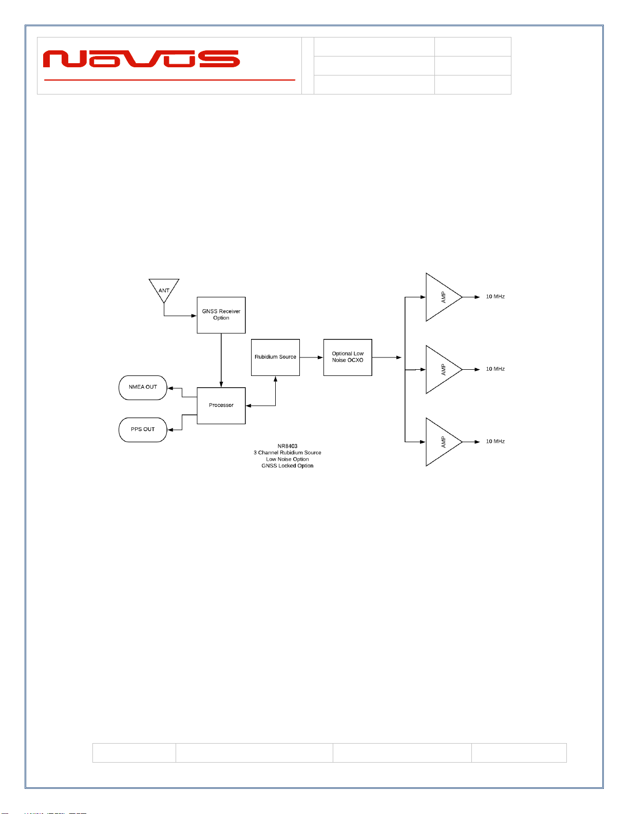
GNSS Receiver (option) ..................................................................................................... 8
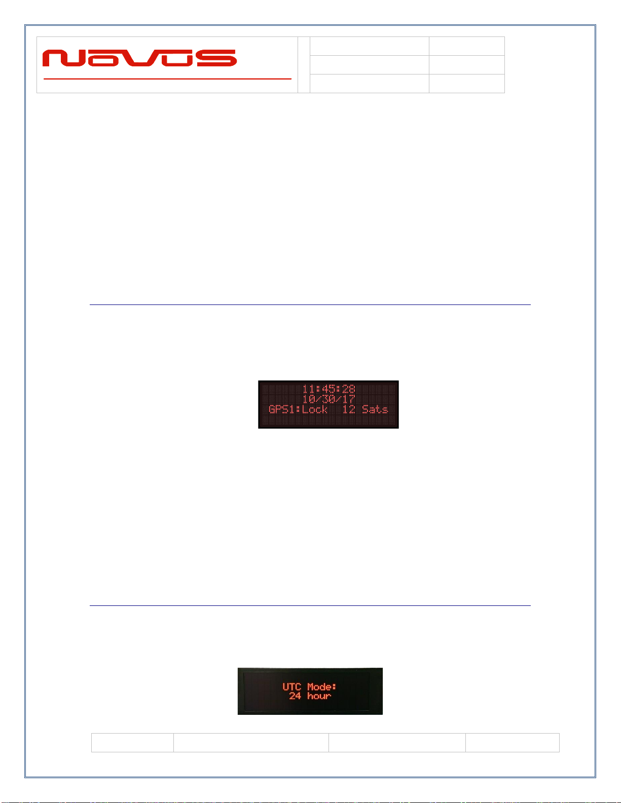
GNSS Status.................................................................................................................... 8
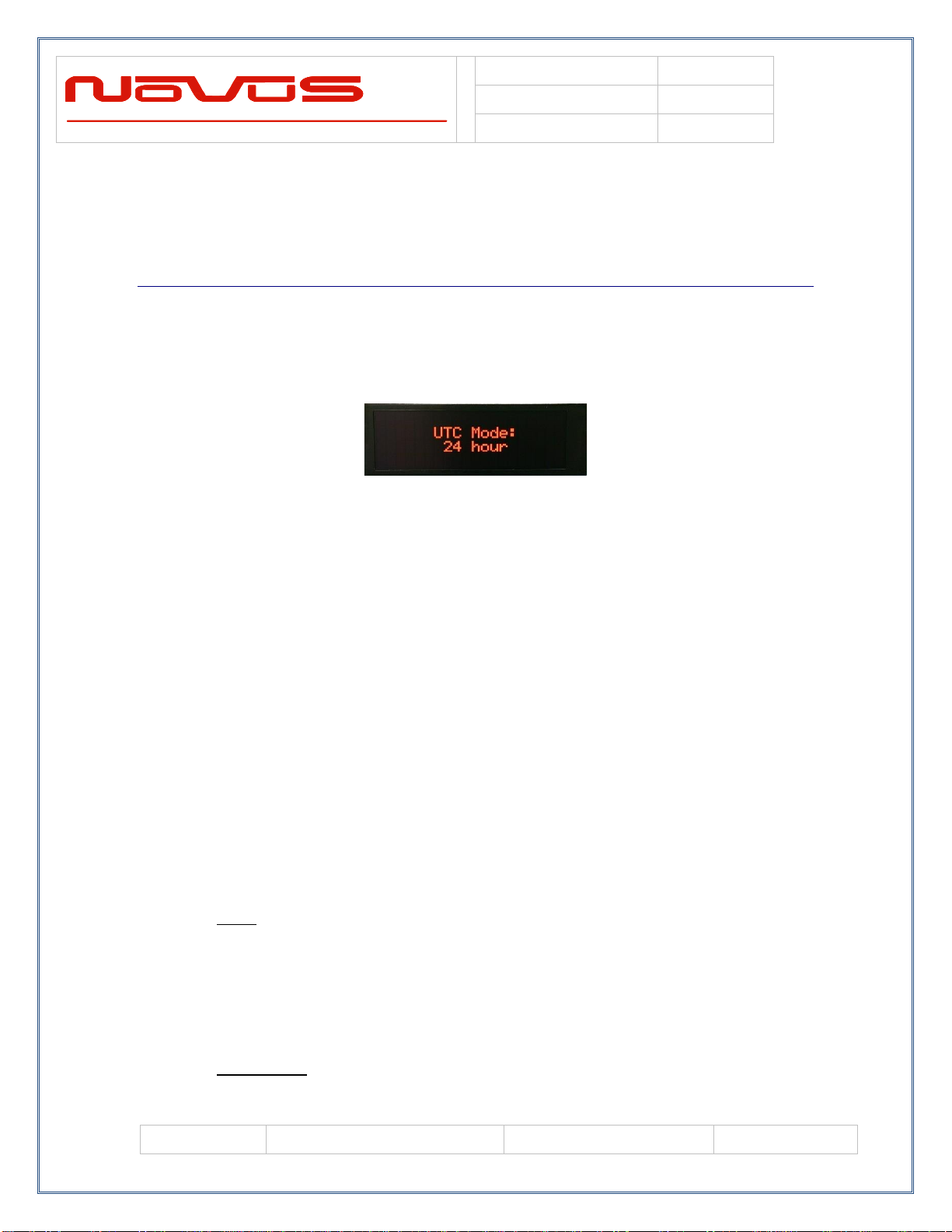
UTC Mode...................................................................................................................... 8
GMT Offset..................................................................................................................... 9
Mechanical........................................................................................................................ 12
Antenna............................................................................................................................. 13
PPS (Pulse Per Second) .................................................................................................... 14
GNSS PPS Availability................................................................................................. 14
GNSS PPS Accuracy .................................................................................................... 15
PPS Holdover................................................................................................................ 15
Cable Delays................................................................................................................. 16
Rear Panel......................................................................................................................... 18
Channel Output –BNC (10MHz Option)..................................................................... 18
Antenna Input - SMA.................................................................................................... 18
DC Input........................................................................................................................ 18
3.4 RS232 DB9 (Status and NMEA)........................................................................... 19
Operations......................................................................................................................... 20
Channel Status .............................................................................................................. 20
Built in Test................................................................................................................... 21
Alert Threshold............................................................................................................. 21
Latch Channel Value..................................................................................................... 24
Save Configuration ....................................................................................................... 25
Fault Status.................................................................................................................... 25
UTC Mode.................................................................................................................... 26
GMT Offset................................................................................................................... 26
Functional Description...................................................................................................... 27
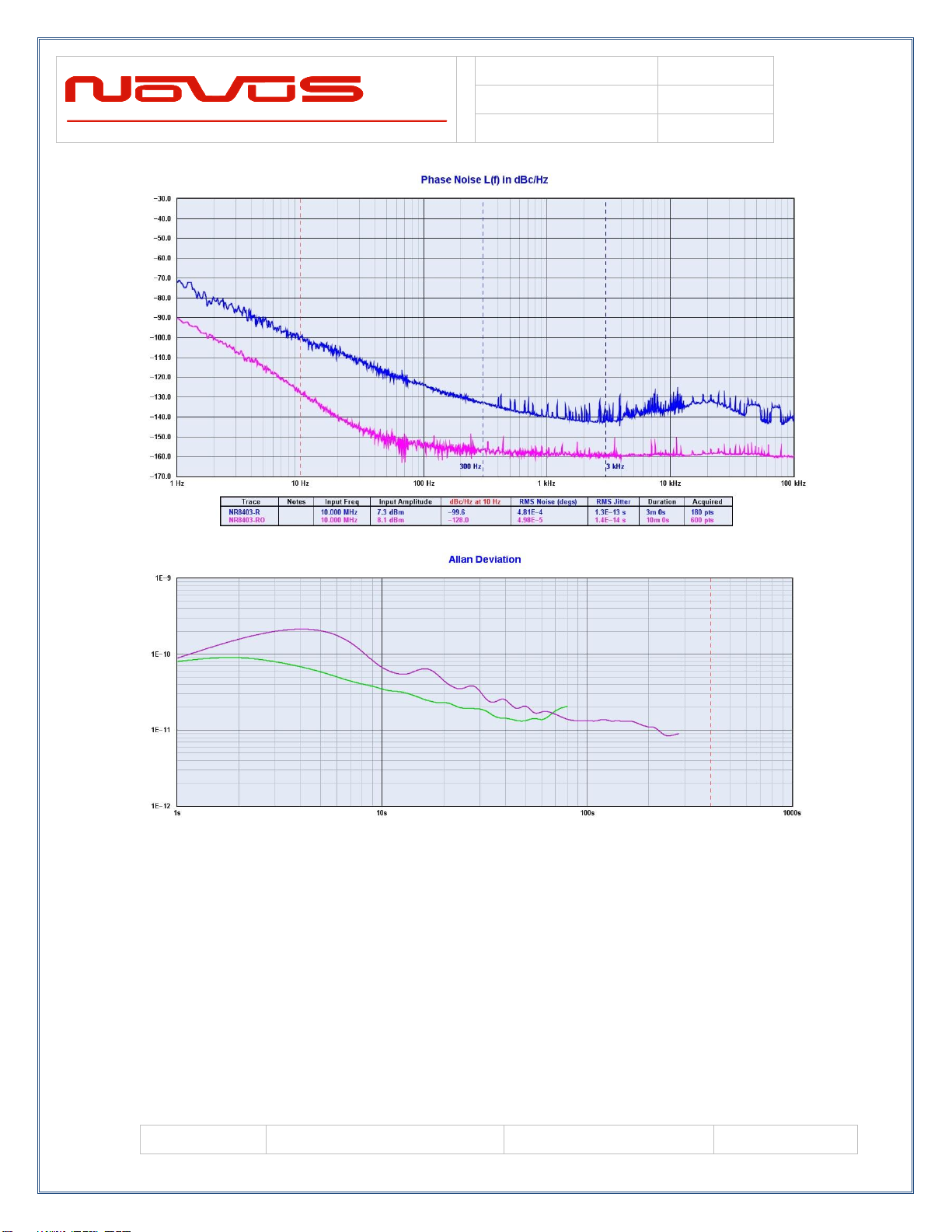
Outputs.......................................................................................................................... 27
Built in Test................................................................................................................... 28
6.0 Calibration................................................................................................................... 28
Programming Guide (RS232 Port: Status Only)............................................................... 28
RS232 Commands (Status Only, for GNSS, see Append. A) ...................................... 29
Technical Specification..................................................................................................... 33
Environmental and Mechanical .................................................................................... 35
9.0 LIMITED HARDWARE WARRANTY.................................................................... 35
Appendix A: GNSS Command Reference........................................................................ 37
Appendix C: $GPNVS Status Strings............................................................................... 37