Sanav MU-201 User manual

a
GPS/GPRS Nano Tracker
MU-201 User Manual
Revision: 1.0.1
Revision Date: 2011/1/5

b
Content
1. Notification ...........................................................................................1
1.1 Introduction:...............................................................................................................1
1.2 Disclaimer.....................................................................................................................1
1.3 Copyright......................................................................................................................1
1.4 Document Amendments.........................................................................................2
2. Specifications: .......................................................................................3
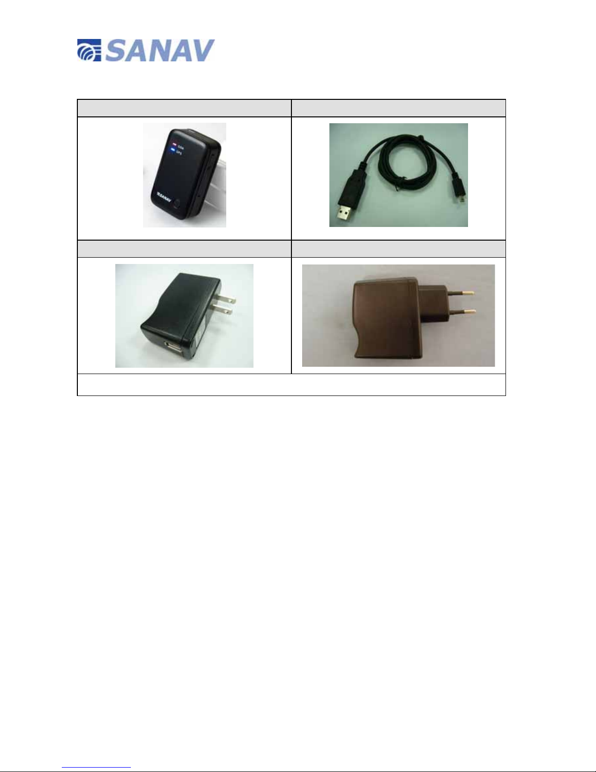
2.1 Package Contents..........................................................................................................4
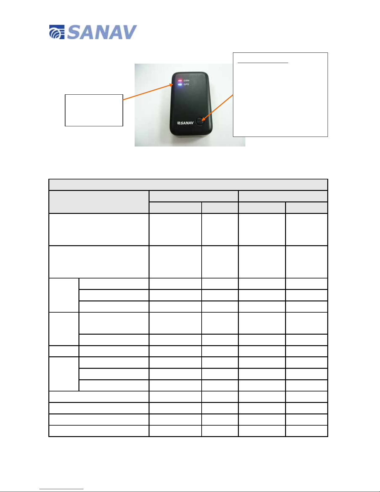
3.1 Front Face.........................................................................................................................5
3.1.1 LED light status of MU-201....................................................................................5
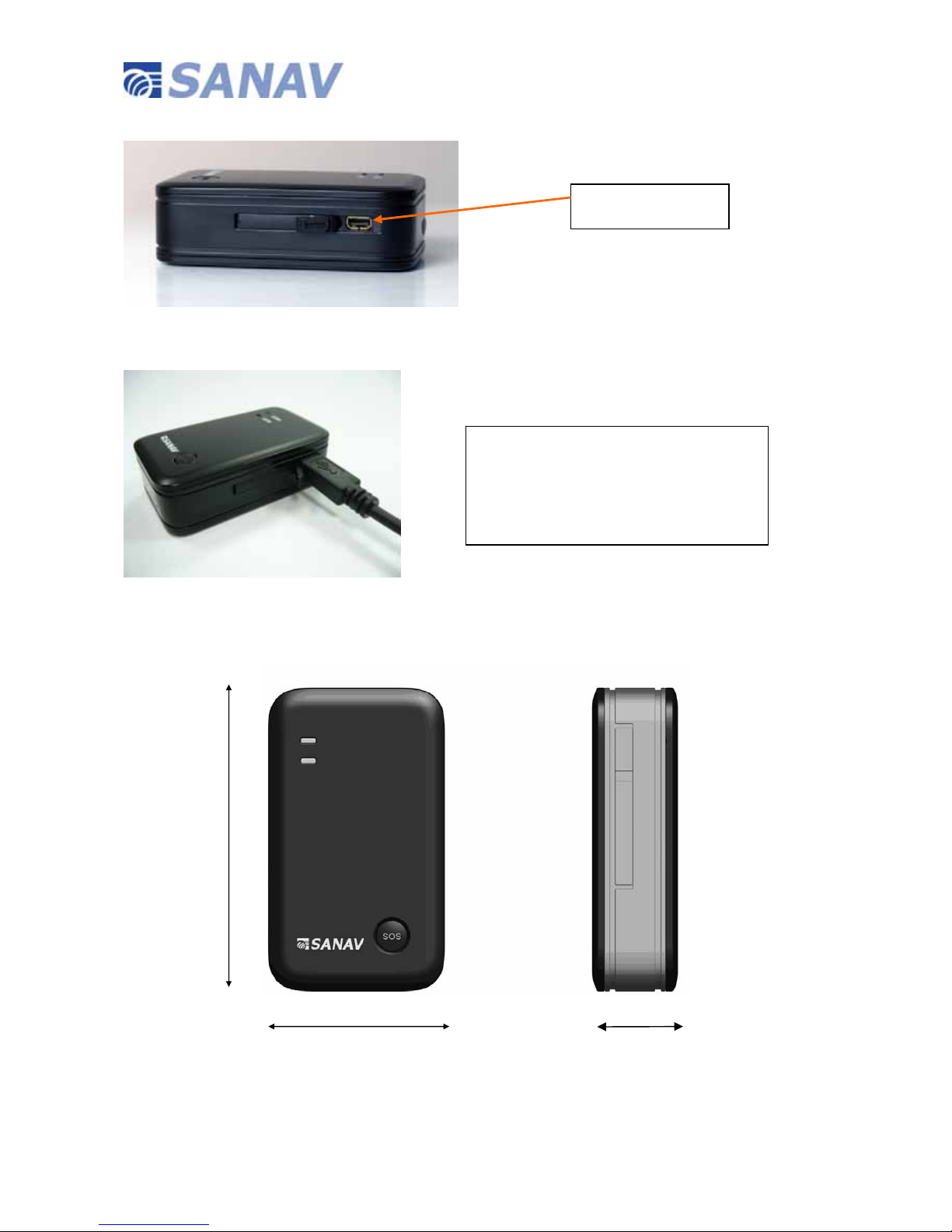
3.3 Bottom Face ....................................................................................................................6
3.4 Side Face ..........................................................................................................................6
3.6 Charging MU-201 ..........................................................................................................7
3.7 Dimension.........................................................................................................................7
4 SMS Command Setup for MU-201 ...............................................................7
4 SMS Command Setup for MU-201 ...............................................................8
4.1 Change Username.........................................................................................................9
4.2 Change Password........................................................................................................10
4.3 Set up APN for Device Report ................................................................................11
4.4 Set up URL for Device Report.................................................................................12
4.5 Set up Phone Number List.......................................................................................13
4.6 Set up SOS Number...................................................................................................14
4.6.2 Set up SOS Report Interval.................................................................................16
4.6.3 Stop SOS Report (Exit from SOS Mode)........................................................17
4.7 Set up Auto Report.....................................................................................................18
4.8 Acquire the Report of Current Position (SMS Polling)...................................19
4.9 Setup Report Interval When Park Is Triggered...............................................20
4.10 Setup Over Speed Detection................................................................................21
4.11 Activate Over Speed Detection ...........................................................................22
4.12 Setup Geofence Coordinate..................................................................................23
4.13 Setup Geofence Alarm Report Interval............................................................24
4.14 Setup Voice Mode.....................................................................................................25
4.15 Setup TCP/UDP Server Address..........................................................................26
4.16 Setup Backup/Log Interval Mode (Pre-defined Backup Times)..............27
4.17 Setup SMS Google Map Report...........................................................................28
4.18 Setup Security Phone Book ..................................................................................29
4.18.2 Enable/Disable Security Phone Book Detection........................................30
5 Respond messages ...............................................................................31
5.1 Output Format When The Router Is Set to HTTP, TCP or UDP .................32

c
5.2 Output Format when The Router Is Set to SMS .............................................33
5.3 NMEA 0183 GPRMC Sentence.................................................................................34
Warranty ..............................................................................................35

1
1. Notification
1.1 Introduction:
SANAV MU-201 is a more compact version of GPS tracker focusing on the covert, pets or asset tracking
market. Its location can be real time tracked through internet or specified terminals. The user can
communicate with the service server through GPRS/GSM network, transfer alarms of Emergency,
Geo-fencing., Remote Control, and Lower power, and record the tracking history stored in internal
memory through USB or website.
This User Manual details the specification, hardware design, SMS commands, and Respond messages of
MU-201. If you have any problem with the content in this manual, please contact SANAV Customer
1.2 Disclaimer
This document, and all other related products, such as device, firmware, and software, is developed by San
Jose Technology Inc. thoroughly. At the time of release, it is most compatible with specified firmware version.
Due to the functionalities of the devices are being developed and improved from time to time, the change in
the protocol, specification, and firmware functions are subjects to change without prior notice. SANAV is
obligated to modify all the documentation without the limitation of time frame. A change notice shall be
released to San Jose Technology Inc. customers upon the completion of document modification.
San Jose Technology Inc. products are not intended to be used as life support or rescue equipments. San
Jose Technology Inc. is not liable for any loss or injury caused by using or referencing to any products. Any
possible means of using or integrating San Jose Technology Inc. products shall be avoided.
1.3 Copyright
The all parts of intellectual rights applicable in the copyright laws in all the countries are held by San Jose
Technology Inc., any or all parts of this document shall not be exposed to non-authorized party without any
form of approval from San Jose Technology Inc. Any forms including but not limited to oral, copy, or internet
sharing, of releasing or exposing information to an unauthorized party shall be prohibited. San Jose
Technology Inc. reserves the rights of litigation in the violation of such copyright laws.

2
1.4 Document Amendments
Revision Date MU-201 Firmware Version Comments
1.0.1 2011/1/5 Beta V2.02 Major Functions implemented

3
2. Specifications:
GSM
Frequency:
Quad-Band: 850/900/1800/1900MHz
Compliant to GSM phase 2/2+
-Class 4 (2W @ 850/900MHz)
-Class 1 (1W @ 1800/1900MHz)
GPRS: GPRS multi-slot class 10
GPRS mobile station class B
RMS Phase Error: ≤5deg
Max Out RF power: 31.0dBm±3dBm
Dynamic Input Range: -15 ~ -102 dBm
Receiving Sensitivity: Class II RBER≤2%(-102dBm)
Stability Of Frequency: Greater than 2.5ppm
Max Frequency Error: ±0.1ppm
GPS
GPS Chipset: u-blox
Sensitivity:
Autonomous Acquisition -144 dBm
Hot start -155 dBm
Tracking -160 dBm
Channels : 20 channel all-in-view tracking
TTFF (Open Sky):
Cold start 40 s average
Warm start <30s
Hot start <2 s
User Interfaces
Mini USB Connector: Include charger
Power Button: Power on and power off.
General
Dimension: 60mm* 35 mm * 17mm
Weight: 65 g
Backup Battery: Li-Polymer 650 mAh , 3.7V
Standby Time: 10 minutes reporting: 50 Hours (estimation)
60 minutes reporting: 100 Hours (estimation)
Charge Voltage 5 V DC
Air Interface Protocol
Transmit Protocol: TCP,UDP,SMS
Geo-Fence: 10 Geo-Fence regions can be defined.
Low Power Alarm: Alarm when battery is low
Power On Report: Report on power up
Environment
Operating Temperature 0°C to +55°C
Storage Temperature -20°C to +85°C
Adapter Temperature 0°C to +40°C
*This specification is subject to change without prior notice

4
2.1 Package Contents
MU-201*1pcs Charging Cable*1pc
Wall Charger*1 100~240V AC / 1.2A)*1pc
Utility CD * 1pc
2.1.1 Optional Accessories:
zAP Data Cable

5
z3. Hardware Description
3.1 Front Face
3.1.1 LED light status of MU-201
MU-201 LED Display Scenario Table
Device Status GSM GPS
Red Green Red Blue
Power on
Long Press Power key for 3 seconds
Steady ON
(Than following
booting)
Power off
Long Press Power key for 3 seconds
Steady ON
Than power
off
Steady ON
Than power off
GPS
Status
Searching GPS Signal - - 1 flash per 5s -
GPS Signal Fixed - - - 1 flash per 5s
GPS sleeping mode - - - -
GSM
Status
Searching GSM Signal
& no servers - - - -
GSM Signal Fixed - 1 flash per 5s - -
SOS Mode In SOS Mode Steady ON - Steady ON -
Park Mode
Park on - - Flash 5 times
In Park Mode Flash once per 5s - - -
Park off - - Flash 5 times
Receive SMS Command - Flash 5 times
- -
Low Power Flash 500ms/sec. - -
Battery Charging - - - Flash 500ms/sec
Battery Full Charged Flash 500ms/sec. - - -
NOTE* Due to the device is still in Beta Version, the above LED Status is subject to change. Please contact SANAV if you have
any question regarding the device LED indication.
SOS/Park Button
zSOS - Press and hold for 3s to
trigger SOS Mode.
zPark - One Short Press to
Enter Park Mode; and one
short press again to exit Park
Mode.
zGSM LED
zGPS LED

6
3.2 TOP Face
3.3 Bottom Face
3.4 Side Face
3.4.1 Correct Way to insert SIM Card (Please note the SIM Card orientation!)
Power button
Turn ON:Long Press for 3 seconds when the device is OFF.
Turn OFF:Long Press for 3 seconds when the device is ON.
(Note* When press the Power button for 3 seconds, you will see both GPS and
GSM LED lit on, then you can let go and the device will shut down afterwards.)
Hidden Microphone (For Voice Monitoring)
SIM Card Holder

7
3.6 Charging MU-201
Plug power cable to Mini USB connector for charging the device. (5V DC Input)
3.7 Dimension
MINI USB 8 PIN
When you charge the device for the 1st
time, please use the power cable that’s
contained in the package, and charge
the device for 2~3 hours.
60 mm
35 mm 19mm

8
4 SMS Command Setup for MU-201
MU-201 currently provides SMS commands for remote setup. You can setup the MU-201 by following the
instructions shown in following chapters via SMS from a cellular phone or GSM modem. Key the specific SMS
message in your cellular phone and send it to the SIM number of MU-201. The setup messages are showed
in the following sections.

9
4.1 Change Username
You can change the ID of MU-201 by following the format below. No space is allowed between the characters. For example,
if you send the SMS message shown in the example below to the MU-201, you will change the ID from “username” to “car”
Setup format:#「username」,「Password」,「Function Code」,「New username」*
Example:#username,0000,1,car*
The table 4.1.1 describes the meaning of each segment in the message above.
Table 4.1.1
The table 1.2 shows each confirmation message reply after setup
Table 4.1.2
Text Keyed In SMS Description
# Start sign.
Username Default ID of MU-201
0000 Default password.
If you have changed the password, please use the updated one.
1 Mode 1 defines the ID setup
Car New ID defined by the owner.
At the maximum of 16 characters, including a~z,A~Z,0~9, @ - _ / .!%&
* End sign.
Situation Message Reply
Setup Succeeds Device username is updated.,4.032V
Setup Fail Username setup Fail!-01- Username is empty or length is too long!,3.926V
MU-201 is in Emergency Mode in emergency, changing username is not allowed.,3.972V

10
4.2 Change Password
Use this SMS message example seen below to change the password of MU-201. For example, by following the example
below, you will change the default password, “0000” to a new password, “1111”.
Setup format:#「username」,「Password」,「Function Code」,「new Password」,「new Password」*
Example:#username,0000,2,1111,1111*
The table 2.1 describes the meaning of each segment in the message above.
Table 4.2.1
The table 4.2.2 shows each confirmation message reply after setup
Table 4.2.2
Text Keyed In SMS Description
# Start sign.
username Default ID of MU-201.
If you have changed the username, please use the updated one.
0000 Default password.
If you have changed the password, please use the updated one.
2 Mode 2 defines to change the password
1111 New password (Please note at the maximum of 4 number)
1111 Reconfirm the password
* End sign.
Situation Message Reply
Setup Succeeds Device Password is updated.,4.020V
Setup Fail Password setup Fail!,3.914V
MU-201 is in Emergency Mode in emergency, changing password is not allowed.,3.945V

11
4.3 Set up APN for Device Report
Use this SMS message to predefine the APN by following the format below.
Setup format: #「username」,「Password」,「Function Code」,「APN name」,「APN username」,「APN password」,
「APN DNS」*
Example:#username,0000,3,Twm,1234,1234, 172.20.2.10*
Note that the total length of APN name, APN username, APN Password, and APN DNS should be lesser than 70
characteristics.
The table 4.3.1 describes the meaning of each segment in the message above.
Table 4.3.1
The table 4.3.2 shows each confirmation message reply after setup
Text Keyed In SMS Description
# Start sign.
username Default ID of MU-201.
If you have changed the Username, please use the updated one.
0000 Default password.
If you have changed the password, please use the updated one.
3 Mode 3 defines the changes of the built-in APN setting.
Twm APN Name
1234 APN Usename
1234 APN Password
172.20.2.10 APN DNS
* End sign.
Situation Message Reply
Setup Succeeds Device GPRS APN is updated.-03- Set up the GPRS APN,3.947V
MU-201 is in Emergency Mode in emergency, GPRS APN setup is not allowed.,3.942V

12
4.4 Set up URL for Device Report
Use this SMS message to predefine the URL by following the format below.
Setup format: #「username」,「Password」,「Function Code」,「URL」*
Example:#username,0000,4,http://www.sanav.com/eric-gga/gprs.aspx*
Note that the URL should be lesser than 80 characteristics.
The table 4.4.1 describes the meaning of each segment in the message above.
Table 4.4.1
The table 4.4.2 shows each confirmation message reply after setup
Text Keyed In SMS Description
# Start sign.
username Default ID of MU-201.
If you have changed the Username, please use the updated one.
0000 Default password.
If you have changed the password, please use the updated one.
4 Mode 4 defines to transmit data to a specific website
http://www.sanav.com/eric-gga/gprs.aspx URL
* End sign.
Situation Message Reply
Setup Succeeds Device IP/Domain is updated.-04- Set up a Host Name (URL) to Transmit Data is
OK,3.947V
MU-201 is in Emergency Mode in emergency, IP/Domain setup is not allowed.,3.942V

13
4.5 Set up Phone Number List
Use this SMS message to predefine the cellular numbers in “Phone Book” (Max. of 3 numbers) by following the format
below.
Setup format: #「username」,「Password」,「Function Code」,「PH-01」,「PH-02」,「PH-03」*
Example:#username,0000,5,+886123456789,+492234567890,+866323456789*
Note that both adding and not adding the “+ “sign in front of the cellular phone number(s) are both acceptable,
while the”+” sign should precede the national code.
The table 4.5.1 describes the meaning of each segment in the message above.
Table 4.5.1
The table 4.5.2 shows each confirmation message reply after setup
Text Keyed In SMS Description
# Start sign.
username Default ID of MU-201.
If you have changed the Username, please use the updated one.
0000 Default password.
If you have changed the password, please use the updated one.
5 Mode 5 defines the changes of the built-in phone number list.
+886123456789 1st cellular numbers, PH-01
+492234567890 2nd cellular numbers, PH-02
+866323456789 3rd cellular numbers, PH-03
* End sign.
Situation Message Reply
Setup Succeeds Device phone book is updated.-05- Setup Phone is OK
,phone1=+886970016355,phone2=+886970016355,phone3=+866970016355,4.013V
MU-201 is in Emergency Mode in emergency, phone book setup is not allowed.,3.939V

14
4.6 Set up SOS Number
Use this SMS message to predefine the SOS cellular numbers by following the format below. MU-201 will first send a SOS
Alert to the SOS phone and then make a phone call to the SOS phone number immediately.
Setup format: #「username」,「Password」,「Function Code」,「SOS Phone」*
Example:#username,0000,sosphone,+886123456789*
Note that both adding and not adding the “+ “sign in front of the cellular phone number(s) are both acceptable,
while the”+” sign should precede the national code.
The table 4.6.1 describes the meaning of each segment in the message above.
Table 4.6.1
The table 4.6.2 shows each confirmation message reply after setup
Text Keyed In SMS Description
# Start sign.
username Default ID of MU-201.
If you have changed the Username, please use the updated one.
0000 Default password.
If you have changed the password, please use the updated one.
sosphone Mode “sosphone” defines the changes of the built-in phone number list.
+886123456789 SOS Phone number
* End sign.
Situation Message Reply
Setup Succeeds Device sos phone book is updated.SOS phone=0955123456,4.016VV
MU-201 is in Emergency Mode in emergency, sos phone book setup is not allowed.,3.920V

15
SOS Algorithm
Press SOS Button
Call SOS Number
Check Phonebook
Send SMS to all numbers
Check SOS Phonebook
Call hangs up
Send data according to preset router
No
Yes
No
Yes

16
4.6.2 Set up SOS Report Interval
Use this SMS message to predefine the SOS report interval by following the format below.
Setup format: #「username」,「Password」,「Function Code」,「SOS report interval」,「SOS report times」*
Example:#username,0000,15,30,3*
Note that SOS report interval ranges from 1~65000 seconds; SOS report times ranges from 1~9999 times.
The table 4.6.2.2 describes the meaning of each segment in the message above.
Table 4.6.2.2
The table 4.6.2.3 shows each confirmation message reply after setup
Text Keyed In SMS Description
# Start sign.
username Default ID of MU-201.
If you have changed the Username, please use the updated one.
0000 Default password.
If you have changed the password, please use the updated one.
15 Function Code
30 It defines the report interval (in this case, one report per 30s) when SOS is triggered.
3 It defines how many times the SOS report will be sent to the defined SOS phone number.
(in this case, 3 times)
* End sign.
Situation Message Reply
Setup Succeeds setup OK. Device Panic report setting is updated.-15-Panic Report Setting,3.950V
MU-201 is in Emergency Mode in emergency, Panic Report setting is not allowed.-15-Panic Report Setting
,4.000V

17
4.6.3 Stop SOS Report (Exit from SOS Mode)
While the device is still in SOS Mode (meaning it’s sending the SOS Alert Report), one can use this SMS message to stop
the SOS report and Exit from SOS mode.
Setup format: #「username」,「Password」,「offpanic」*
Example: #username,0000,offpanic*
Note: Users can enter or exit SOS Mode by pressing the SOS button on the device, too. See Chapter 2,
Hardware Description.
The table 4.6.3.1 shows each confirmation message reply after setup
Situation Message Reply
Setup Succeeds Device OffPanic is Done and switching to normal mode.,3.806V
Other manuals for MU-201
1
Table of contents
Other Sanav GPS manuals

Sanav
Sanav GC-101 User manual

Sanav
Sanav GX-101 User manual

Sanav
Sanav GS-818 User manual

Sanav
Sanav MU-201 S1 User manual

Sanav
Sanav GC-101 User manual

Sanav
Sanav TRACKSTARIII User manual

Sanav
Sanav SANAV FV-M7 User manual

Sanav
Sanav MU-201 User manual

Sanav
Sanav G-19B User manual

Sanav
Sanav GC-101 User manual