Novus AIRGATE-3G User manual

NOVUS AUTOM ATI ON 1/119
NOVUS AirGate-3G
Dual SIM Industrial Cellular VPN Router
For GPRS/UMTS/HSPA Networks
User Manual
V1.0x D
About This Document
This document describes hardware and software of NOVUS AIRGATE-3G, Dual SIM Industrial 2G/3G Router.
Copyright© NOVUS PRODUTOS ELETRONICOS LTDA
All Rights Reserved.
Trademarks and Permissions
NOVUS are trademark of NOVUS Produtos Eletrônicos LTDA.
All other trademarks and trade names mentioned in this document are the property of their respective
holders.
Disclaimer
No part of this document may be reproduced in any form without the written permission of the copyright
owner.
The contents of this document are subject to revision without notice due to continued progress in
methodology, design and manufacturing. NOVUS shall have no liability for any error or damage of any kind
resulting from the use of this document.
Technical Support Contact Information
Tel: +55 51 3323-3600
Fax: +55 51 3323-3644
E-mail: support@novusautomation.com
Web: www.novusautomation.com

AirGate-3G
NOVUS AUTOM ATI ON 1/119
Important Notice
Due to the nature of wireless communications, transmission and reception of data can never be guaranteed.
Data may be delayed, corrupted (i.e., have errors) or be totally lost. Although significant delays or losses of
data are rare when wireless devices such as the router are used in a normal manner with a
well-constructed network, the router should not be used in situations where failure to transmit or receive
data could result in damage of any kind to the user or any other party, including but not limited to personal
injury, death, or loss of property. NOVUS accepts no responsibility for damages of any kind resulting from
delays or errors in data transmitted or received using the router, or for failure of the router to transmit or
receive such data.
Safety Precautions
General
The router generates radio frequency (RF) power. When using the router care must be taken on safety
issues related to RF interference as well as regulations of RF equipment.
Do not use your router in aircraft, hospitals, petrol stations or in places where using cellular products is
prohibited.
Be sure that the router will not be interfering with nearby equipment. For example: pacemakers or
medical equipment. The antenna of the router should be away from computers, office equipment,
home appliance, etc.
An external antenna must be connected to the router for proper operation. Only uses approved
antenna with the router. Please contact authorized distributor on finding an approved antenna.
Always keep the antenna with minimum safety distance of 26.6 cm or more from human body. Do not
put the antenna inside metallic box, containers, etc.
RF exposure statements
1. For mobile devices without co-location (the transmitting antenna is installed or located more than
20cm away from the body of user and nearby person)
FCC RF Radiation Exposure Statement
1. This Transmitter must not be co-located or operating in conjunction with any other antenna or
transmitter.
2. This equipment complies with FCC RF radiation exposure limits set forth for an uncontrolled
environment. This equipment should be installed and operated with a minimum distance of 20
centimeters between the radiator and your body.
Note: Some airlines may permit the use of cellular phones while the aircraft is on the ground and the door is
open. Router may be used at this time.
Using the router in vehicle
Check for any regulation or law authorizing the use of cellular in vehicle in your country before
installing the router.
The driver or operator of any vehicle should not operate the route while in control of a vehicle.
Install the router by qualified personnel. Consult your vehicle distributor for any possible interference
of electronic parts by the router.
The router should be connected to the vehicle’s supply system by using a fuse-protected terminal in
the vehicle’s fuse box.
Be careful when the router is powered by the vehicle’s main battery. The battery may be drained after
extended period.
Protecting your router
To ensure error-free usage, please install and operate your router with care. Do remember the follow:

AirGate-3G
NOVUS AUTOM ATI ON 2/119
Do not expose the router to extreme conditions such as high humidity / rain, high temperatures, direct
sunlight, caustic / harsh chemicals, dust, or water.
Do not try to disassemble or modify the router. There is no user serviceable part inside and the
warranty would be void.
Do not drop, hit or shake the router. Do not use the router under extreme vibrating conditions.
Do not pull the antenna or power supply cable. Attach/detach by holding the connector.
Connect the router only according to the instruction manual. Failure to do it will void the warranty.
In case of problem, please contact authorized distributor.

AirGate-3G
NOVUS AUTOM ATI ON 3/119
Regulatory and Type Approval Information
Table 1: Directives
2002/95/EC
Directive of the European Parliament and of the Council of 27 January 2003
on the restriction of the use of certain hazardous substances in electrical and
electronic equipment (RoHS)
2002/96/EC Directive of the European Parliament and of the Council on waste electrical and electronic
equipment (WEEE)
2003/108/EC
Directive of the European Parliament and of the Council of 8 December
2003 amending directive 2002/96/ec on waste electrical and electronic
equipment (WEEE)
Table 2: Standards of the Ministry of Information Industry of the People’s Republic of China
SJ/T
11363-2006
“Requirements for Concentration Limits for Certain Hazardous Substances in Electronic
Information Products” (2006-06).
SJ/T
11364-2006
“Marking for Control of Pollution Caused by Electronic Information Products”
(2006-06).
According to the “Chinese Administration on the Control of Pollution caused
by Electronic Information Products” (ACPEIP) the EPUP, i.e., Environmental
Protection Use Period, of this product is 20 years as per the symbol shown here, unless
otherwise marked. The EPUP is valid only as long as the product is operated within the
operating limits described in the Hardware Interface Description.
Please see Table 3 for an overview of toxic or hazardous substances or elements that
might be contained in product parts in concentrations above the limits defined by SJ/T
11363-2006.
Table 3: Toxic or hazardous substances or elements with defined concentration limits
Name of the part Hazardous substances
(Pb) (Hg) (Cd) (Cr(VI)) (PBB) (PBDE)
Metal Parts o o o o o o
Circuit Modules x o o o o o
Cables and Cable Assemblies o o o o o o
Plastic and Polymeric parts o o o o o o
o: Indicates that this toxic or hazardous substance contained in all of the homogeneous materials for this
part is below the limit requirement in SJ/T11363-2006.
X: Indicates that this toxic or hazardous substance contained in at least one of the homogeneous materials
for this part might exceed the limit requirement in SJ/T11363-2006.

AirGate-3G
NOVUS AUTOM ATI ON 4/119
Contents
1. PRODUCT CONCEPT....................................................................................................................................... 6
1.1 Overview..................................................................................................................................... 6
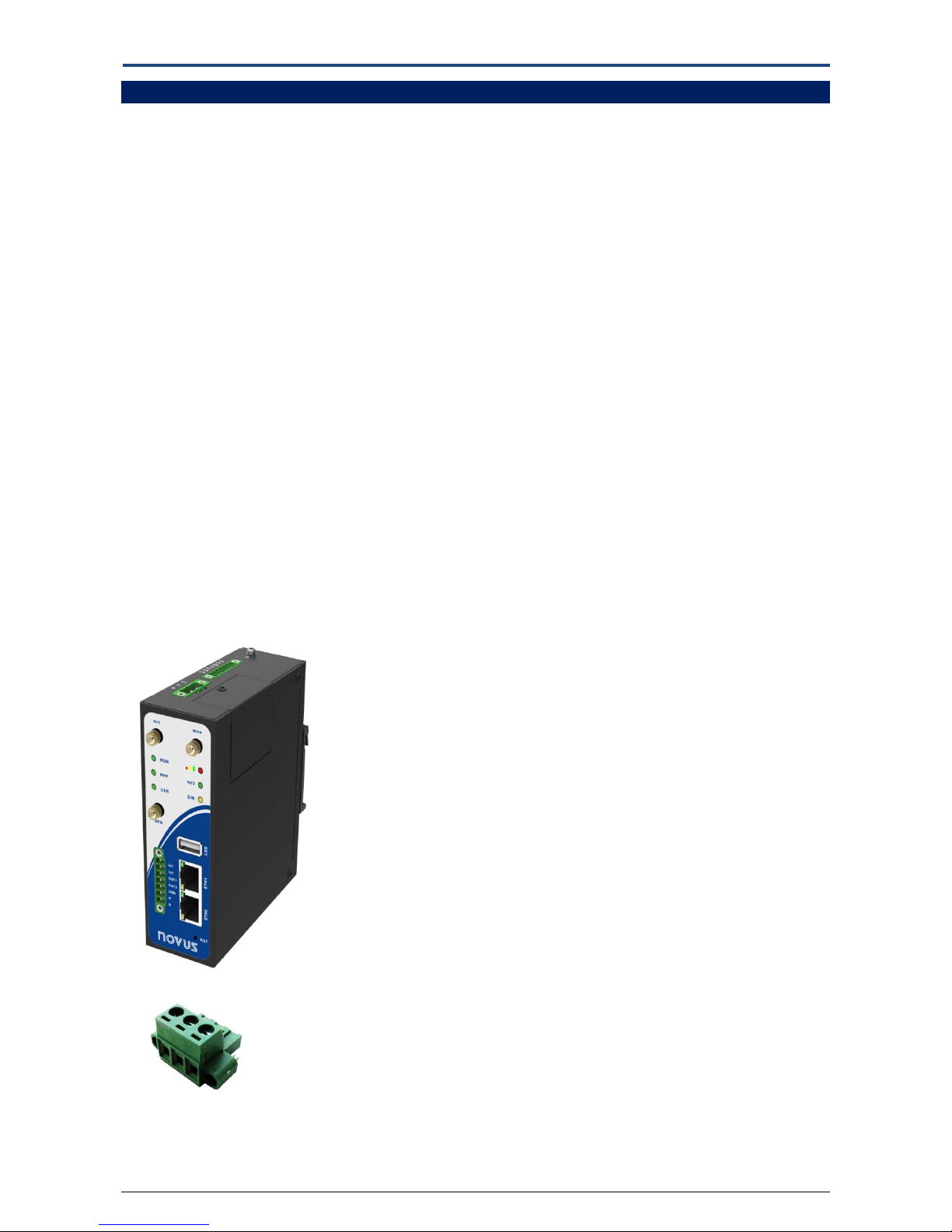
1.2 Packing List.................................................................................................................................. 6
1.3 Specifications .............................................................................................................................. 8
1.4 Selection and Ordering Data..................................................................................................... 10
2. Installation ............................................................................................................................................... 11
2.1 LED Indicators ........................................................................................................................... 11
2.2 PIN Assignment......................................................................................................................... 12
2.3 USB Interface ............................................................................................................................ 12
2.4 Reset Button ............................................................................................................................. 13
2.5 Ethernet Ports........................................................................................................................... 13
2.6 Mount the Router..................................................................................................................... 14
2.7 Install SIM Card and Micro SD Card .......................................................................................... 14
2.8 Connect the External Antenna.................................................................................................. 15
2.9 Ground the Router.................................................................................................................... 15
2.10 Power Supply ............................................................................................................................ 16
3. Configuration Settings over Web Browser............................................................................................... 17
3.1 Configuring PC in Windows ...................................................................................................... 17
3.2 Factory Default Settings............................................................................................................ 19
3.3 Control Panel ............................................................................................................................ 19
3.4 Status -> System........................................................................................................................ 21
3.5 Status -> Network ..................................................................................................................... 24
3.6 Status -> Route.......................................................................................................................... 25
3.7 Status -> VPN ............................................................................................................................ 25
3.8 Status -> Services ...................................................................................................................... 26
3.9 Status ->Channels ..................................................................................................................... 27
3.10 Status -> Event/Log................................................................................................................... 28
3.11 Configuration -> Link Management .......................................................................................... 29
3.12 Configuration -> Cellular WAN.................................................................................................. 30
3.13 Configuration -> Ethernet ......................................................................................................... 35
3.14 Configuration -> Serial .............................................................................................................. 38
3.15 Configuration -> DI/DO ............................................................................................................. 45
3.16 Configuration -> Remote Channels........................................................................................... 48
3.17 Configuration->Modbus over TCP............................................................................................. 49
3.18 Configuration -> GPS................................................................................................................. 49
3.19 Configuration -> NOVUS Cloud ................................................................................................. 52
3.20 Configuration -> FTP ................................................................................................................. 53
3.21 Configuration ->SMTP............................................................................................................... 54
3.22 Configuration -> SNMP ............................................................................................................. 54
3.23 Configuration -> Event .............................................................................................................. 56
3.24 Configuration -> Phone Book.................................................................................................... 57
3.25 Configuration -> SMS ................................................................................................................ 58
3.26 Configuration ->Alarms............................................................................................................. 59
3.27 Configuration -> NAT/DMZ........................................................................................................ 60
3.28 Configuration -> Firewall........................................................................................................... 61

AirGate-3G
NOVUS AUTOM ATI ON 5/119
3.29 Configuration -> DynDNS.......................................................................................................... 64
3.30 Configuration -> IPSec............................................................................................................... 65
3.31 Configuration -> L2TP ............................................................................................................... 69
3.32 Configuration -> PPTP ............................................................................................................... 72
3.33 Configuration -> OpenVPN ....................................................................................................... 75
3.34 Configuration -> GRE................................................................................................................. 80
3.35 Configuration -> QoS................................................................................................................. 81
3.36 Configuration -> AT over IP ....................................................................................................... 84
3.37 Configuration -> IP Routing....................................................................................................... 84
3.38 Configuration -> NovusLink....................................................................................................... 86
3.39 Configuration -> VRRP .............................................................................................................. 86
3.40 Configuration -> USB................................................................................................................. 87
3.41 Configuration -> USR LED.......................................................................................................... 87
3.42 Configuration -> Syslog ............................................................................................................. 88
3.43 Configuration -> Reboot ........................................................................................................... 88
3.44 Administration -> Profile........................................................................................................... 89
3.45 Administration -> Tools ............................................................................................................. 90
3.46 Administration -> Clock............................................................................................................. 93
3.47 Administration -> Web Server .................................................................................................. 94
3.48 Administration -> User Management ....................................................................................... 95
3.49 Administration -> SDK Management ........................................................................................ 95
3.50 Administration -> Update Firmware ......................................................................................... 96
4. Configuration Examples ........................................................................................................................... 97
4.1 Interface.................................................................................................................................... 97
4.1.1 Console Port...................................................................................................................... 97
4.1.2 Digital Input....................................................................................................................... 97
4.1.3 Digital Output.................................................................................................................... 97
4.1.4 RS232................................................................................................................................. 98
4.1.5 RS485................................................................................................................................. 98
4.2 Cellular...................................................................................................................................... 99
4.2.1 Cellular Dial-Up ................................................................................................................. 99
4.2.2 SMS Remote Status Reading ........................................................................................... 102
4.3 Network .................................................................................................................................. 103
4.3.1 NAT .................................................................................................................................. 103
4.3.2 L2TP................................................................................................................................. 104
4.3.3 PPTP ................................................................................................................................ 105
4.3.4 IPSEC VPN........................................................................................................................ 107
4.3.5 OPENVPN ........................................................................................................................ 109
5. Introductions for CLI .............................................................................................................................. 112
5.1 What’s CLI and Hierarchy Level Mode .................................................................................... 112
5.2 How to Configure the CLI........................................................................................................ 113
5.3 Commands Reference............................................................................................................. 117
6. Warranty ................................................................................................................................................ 118

AirGate-3G
NOVUS AUTOM ATI ON 6/119
1. PRODUCT CONCEPT
1.1 OVERVIEW
NOVUS AirGate-3G is a rugged cellular router offering state-of-the-art mobile connectivity for machine to machine (M2M)
applications.
Dual SIM redundancy for continuous cellular connections, supports 2G/3G.
WAN link management: cellular WAN/Ethernet WAN backup.
VPN tunnel: IPSec/OpenVPN/PPTP/L2TP/GRE.
Supports Modbus gateway (Modbus RTU/ASCII to Modbus TCP).
Supports GPS&GLONASS (optional), provides real time location and tracking.
Supports SDK, provides user programmatic interface.
Supports 802.1Q VLAN Trunk.
Supports PPPoE Bridge (IP Passthrough).
Auto reboot via SMS/Caller ID/Timing.
Supports NovusLink (Centralized M2M management platform, to remote monitor, configure and update firmware).
Flexible Management methods: Web/CLI/SNMP/NovusLink.
Firmware upgrade via Web/CLI/USB/SMS/NovusLink.
Various interfaces: RS232/RS485/Console/DI/DO/USB/Ethernet.
Wide range input voltages from 9 to 60 VDC and extreme operating temperature.
The metal enclosure can be mounted on a DIN-rail or on the wall, also with extra ground screw.
1.2 PACKING LIST
Check your package to make sure it contains the following items:
NOVUS AirGate-3G router x 1
3-pin pluggable terminal block with lock for power connector x 1
7-pin pluggable terminal block with lock for serial port, I/O and console port x 1

AirGate-3G
NOVUS AUTOM ATI ON 7/119
SMA Antenna (Magnet) x 1
Ethernet cable x 1
35mm Din-Rail mounting kit
CD with user guide x 1
Note: Please notify your sales representative if any of the above items are missing or damaged.
Optional accessories (purchased separately):
SMA antenna Stubby - optional
Wall Mounting Kit

AirGate-3G
NOVUS AUTOM ATI ON 8/119
AC/DC Power Supply Adapter (12VDC, 1.5A) x 1 (EU, US, UK, AU plug optional)
1.3 SPECIFICATIONS
Cellular Interface
Standards: GSM/GPRS/EDGE/UMTS/HSPA/EVDO
GPRS/EDGE: 850/900/1800/1900 MHz
HSPA+: 850/900/1900/2100 MHz, DL/UL 21/5.76 Mbps, fallback to 2G
SIM: 2 x (3V & 1.8V)
Antenna Interface: SMA Female
Use telemetry SIM card preferably
Ethernet Interface
Number of Ports: 2 x 10/100 Mbps, 2 LANs or 1 LAN and 1 WAN
Isolation Protection: 1.5kV
Digital Input
Type: 2 x DI, Dry Contact
Dry Contact: On: open, Off: short to GND
Isolation: 3K VDC or 2K Vrms
Absolute Maximum VDC: 5V
Digital Filtering Time Interval: Software selectable
Interface: 3.5mm terminal block with lock
Digital Output
Type: 2 x DO, Sink
Isolation: 3K VDC or 2K Vrms
Absolute Maximum VDC: 30V
Absolute Maximum ADC: 300mA
Interface: 3.5mm terminal block with lock
Serial Interface
Number of Ports: 1 x RS-232 and 1 x RS-485
ESD Protection: ±15kV
Parameters: 8E1, 8O1, 8N1, 8N2, 7E2, 7O2, 7N2, 7E1
Baud Rate: 300bps to 230400bps
RS-232: TxD, RxD, RTS, CTS, GND
RS-485: Data+ (A), Data- (B)
Interface: 3.5mm terminal block with lock

AirGate-3G
NOVUS AUTOM ATI ON 9/119
GPS & GLONASS Interface (Optional)
Antenna Interface: SMA Female, 50 ohms impedance
Tracking Sensitivity: GPS: better than -148 dBm
GLONASS: better than -140 dBm
Horizontal position accuracy: GPS: 2.5 m
GLONASS: 4.0 m
Time-To-First-Fix: GPS: 26 s
GLONASS: 30 s
Protocol: NMEA-0183 V2.3
System
LED Indicators: RUN, PPP, USR, RSSI, NET and SIM
Built-in RTC, Watchdog, Timer
Expansion: 1 x USB 2.0 up to 480 Mbps
Storage: 1 x MicroSD
Micro SD Card – Unlimited storage. FAT file system required.
USB Flash Drive – Unlimited storage. FAT file system required.
Internal flash memory for data cache system – 180 Megabytes.
Software
Network protocols: PPP, PPPoE, TCP, UDP, DHCP, ICMP, NAT, DMZ, RIP v1/v2, OSPF, DDNS, VRRP, HTTP, HTTPs, DNS, ARP, QoS,
SNTP, Telnet, VLAN, SSH2, IP Passthrough.
VPN tunnel: IPSec/OpenVPN/PPTP/L2TP/GRE
Firewall: SPI, anti-DoS, Filter, Access Control
Management: Web, CLI, SNMP v1/v2/v3, SMS, NovusLink
Serial Port: TCP client/server, UDP, Modbus RTU/ASCII to Modbus TCP, Virtual COM (COM port redirector)
NovusLink: Centralized M2M management platform
Power Supply and Consumption
Power Supply Interface: 5mm terminal block with lock
Input Voltage: 9 to 60 VDC
Power Consumption: Idle: 100 mA @ 12 V
Data Link: 400 mA (peak) @ 12 V
Physical Characteristics
Housing & Weight: Metal, 500g
Dimension: (L x W x H): 125 x 108 x 45 mm
Installation: 35mm Din-Rail or wall mounting or desktop
Regulatory and Type Approvals
Approval & Detective: ANATEL, CE, R&TTE,FCC, PTCRB, GCF, AT&T, IC,
Rogers, RCM, CB, E-Mark, NBTC, RoHS, WEEE

AirGate-3G
NOVUS AUTOM ATI ON 10/119
EMI : EN 55022 (2006/A1: 2007) Class B
EMC: EN 61000-4-2 (ESD) Level 4, EN 61000-4-3 (RS) Level 4
EN 61000-4-4 (EFT) Level 4, EN 61000-4-5 (Surge) Level 3
EN 61000-4-6 (CS) Level 4, EN 61000-4-8 Level 4
Environmental Limits
Model No. Description Operating Environment
AIRGATE-3G HSPA+ Router -40 to 85°C/5 to 95% RH
AIRGATE-3G-GPS HSPA+ Router & GPS -40 to 85°C/5 to 95% RH
1.4 SELECTION AND ORDERING DATA
Please refer to corresponding AIRGATE-3G datasheet.

AirGate-3G
NOVUS AUTOM ATI ON 11/119
2. INSTALLATION
2.1 LED INDICATORS
Note: User can select display status of USR LED. Please check section 23.41.
Name Color Status Function
RUN Green
Blinking Router is ready.
On Router is starting.
Off Router is power off.
PPP Green
Blinking PPP Indicator: Null
On PPP Indicator: PPP connection is up.
Off PPP Indicator: PPP connection is down.
USR Green On/Blinking VPN tunnel/PPPoE/DynDNS/GPS is up.
Off VPN tunnel/PPPoE/DynDNS/GPS is down.
Green On Signal level: 21-31 (Perfect signal level).
Yellow On Signal level: 11-20 (Average signal level).
Red On Signal level: 1-10 (Exceptional signal level).
NET
Yellow
Blinking 3G is connected but PPP connection is failed.
On 3G is connected and PPP connection is established.
Red Blinking 2G is connected but PPP connection is failed.
On 2G is connected and PPP connection is established.
/ Off Cannot register to any network.
SIM
Green Blinking Only SIM 1 is detected, but PIN code is incorrect.
On Working with SIM 1 normally.
Yellow Blinking Only SIM 2 is detected, but PIN code is incorrect.
On Working with SIM 2 normally.
Green &
Yellow
Blinking between
two colors Two SIMs are detected, but both of their PIN codes are incorrect.
/ Off No SIM inside.

AirGate-3G
NOVUS AUTOM ATI ON 12/119
2.2 PIN ASSIGNMENT
1
2
3
4
5
6
7
2.3 USB INTERFACE
8
9
10
11
12
13
14
15
16
17
USB interface is used for batch firmware upgrade, cannot used to send or receive data
from slave devices which with USB interface.
Users can insert a USB storage device, such as U disk or hard disk, into the router’s USB
interface, if there is configuration file or firmware of AIRGATE-3G inside the USB storage
devices, AIRGATE-3G will automatically update the configuration file or firmware. Details
please refer to section 23.16.
USB
PIN Debug RS232 Direction
1 RXD Device →AI RG ATE -3G
2 TXD AIRGATE-3G →Device
3 GND GND
4 TXD AIRGATE-3G →Device
5 RXD Device →AI RG ATE -3G
6 RTS AIRGATE-3G →Device
7 CTS Device →AI RGATE -3G
PIN Power Digital I/O RS485
8 Positive
9 Negative
10 GND
11 Input 1
12 Input 2
13 Output 1
14 Output 2
15 GND
16 Data+(A)
17 Data- (B)

AirGate-3G
NOVUS AUTOM ATI ON 13/119
2.4 RESET BUTTON
2.5 ETHERNET PORTS
Each Ethernet port has two LED indicators (please check the following picture). The yellow one is Speed indicator and the green one
is Link indicator. There are three status of each indicator. Please refer to the form below.
Indicator Status Description
Speed Indicator Off 10 Mbps mode.
On 100 Mbps mode.
Link Indicator
Off Connection is down.
On Connection is up.
Blink Data is being transmitted
Function Operation
Reboot Push the button for 5 seconds under working status.
Restore to factory
default setting
Push the button for 60 seconds once you power on the
router until all the LEDs blink at the same time for 5 times.
Reset Button

AirGate-3G
NOVUS AUTOM ATI ON 14/119
2.6 MOUNT THE ROUTER
Use 2 pcs of M3 screw to mount the router on the wall.
Or mount the router on a DIN rail with 3 M3 screws.
2.7 INSTALL SIM CARD AND MICRO SD CARD
Inserting SIM Card or Micro SD Card
1. Make sure power supply is disconnected.
2. Use a screwdriver to unscrew the screw on the cover, and then remove the cover, you could find the SIM Card slots and the
Micro SD slot.
3. Insert the SIM card or Micro SD card, and you need press the card with your fingers until you hear “a cracking sound”. Then
use a screwdriver to screw the cover.

AirGate-3G
NOVUS AUTOM ATI ON 15/119
Removing SIM Card or Micro SD Card
1. Make sure router is power off.
2. Press the card until you hear “a cracking sound”, when the card will pop up to be pulled out.
Note:
1. Please use the specific M2M SIM card when the device works in extreme temperature (temperature exceeding 0 -40 °C
because the long-time working of regular SIM card in harsh environment (temperature exceeding 0 - 40
℃
may increase the
possibility of SIM card failure).
2. Don’t forget screw the cover for again-theft.
3. Don’t touch the metal surface of the SIM card in case information in the card is lost or destroyed.
4. Don’t bend or scratch your SIM card. Keep the card away from electricity and magnetism.
5. Make sure router is power off before inserting or removing your SIM card or Micro SD card.
2.8 CONNECT THE EXTERNAL ANTENNA
Connect router with an external antenna connector. Make sure the antenna is basing on the correct frequency and is screwed
tightly.
2.9 GROUND THE ROUTER
Grounding and wire routing help limit the effects of noise due to electromagnetic interference (EMI). Run the ground connection
from the ground screw to the grounding surface prior to connecting devices.
Note: This product is intended to be mounted to a well-grounded mounting surface, such as a metal panel.
Screw
SMA Male antenna connector for Cellular
SMA Male antenna
connector for GPS

AirGate-3G
NOVUS AUTOM ATI ON 16/119
2.10 POWER SUPPLY
The power supply range is 9 to 60 VDC.
Note: Please take care about the polarity, and do not make reverse connection. There are two lines connecting to the power supply
adapter, as it illustrates on the label. The line printed with letters needs to connect with the positive polarity, and the striped line
needs to connect with the negative polarity.

AirGate-3G
NOVUS AUTOM ATI ON 17/119
3. CONFIGURATION SETTINGS OVER WEB BROWSER
The router can be configured through your web browser. A web browser is included as a standard application in the following
operating systems: Linux, Mac OS, Windows 98/NT/2000/XP/Me/Vista/7/8, etc. The product provides an easy and user-friendly
interface for configuration.
There are various ways to connect the router, either through an external repeater/hub or connect directly to your PC. However,
make sure that your PC has an Ethernet interface properly installed prior to connecting the router.
You must configure your PC to obtain an IP address through a DHCP server or a fixed IP address that must be in the same subnet as
the router. The best and easiest way is to configure the PC to get an IP address automatically from the router using DHCP. If you
encounter any problems accessing the router web interface it is advisable to uninstall your firewall program on your PC, as these
tend to cause problems accessing the IP address of the router.
3.1 CONFIGURING PC IN WINDOWS
1. Go to Start / Control Panel (in Classic View). In the Control Panel, double-click Network Connections, and then, Change
Network Adapter Settings.
2. Double-click Local Area Connection.
3. In the Local Area Connection Status window, click Properties.

AirGate-3G
NOVUS AUTOM ATI ON 18/119
4. Select Internet Protocol Version 4 (TCP/IPv4) and click Properties.
5. Select the Obtain an IP address automatically and Obtain DNS server address automatically radio buttons.
6. Click OK to finish the configuration.

AirGate-3G
NOVUS AUTOM ATI ON 19/119
3.2 FACTORY DEFAULT SETTINGS
Before configuring your router, you need to know the following default settings.
Item Description
Username admin
Password admin
Eth0 192.168.0.1/255.255.255.0, LAN mode
Eth1 192.168.0.1/255.255.255.0, LAN mode
DHCP Server Enabled.
3.3 CONTROL PANEL
This section allows users to save configuration, reboot router, logout and select language.
Table of contents
Other Novus Network Router manuals
Popular Network Router manuals by other brands

ZyXEL Communications
ZyXEL Communications Prestige 2602HW-C Series quick start guide

Macsense
Macsense PalmRouter PR-100 quick start guide

HP
HP MSR930 Series Product End-of-Life Disassembly Instructions

Matrix Switch Corporation
Matrix Switch Corporation MSC-1HD1616L product manual

3Com
3Com MSR 20-40 release note

Phoenix Contact
Phoenix Contact PSI-MODEM-3G/ROUTER user manual