Novus AirGate-GPRS User manual

NOVUS AUTOMATION 1/29
AirGate-GPRS
INSTRUCTION MANUAL
V1.0x
INTRODUCTION.................................................................................................................................................................3
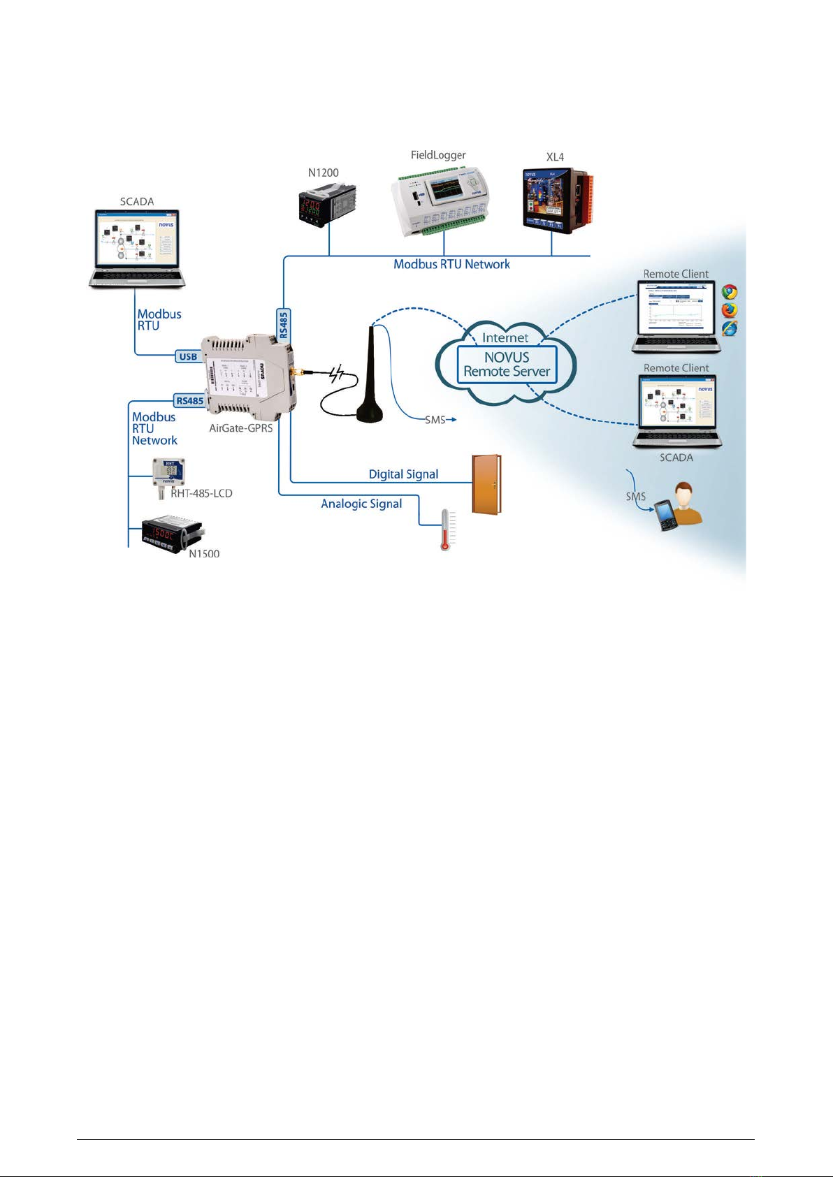
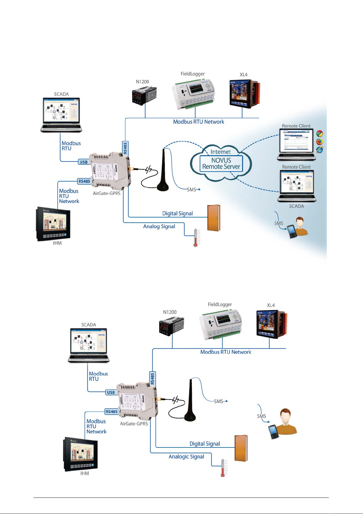
TYPICAL APPLICATIONS..................................................................................................................................................4
SPECIFICATIONS ..............................................................................................................................................................7
CONNECTIONS AND INSTALLATION...............................................................................................................................8
MECHANICAL INSTALLATION..................................................................................................................................... 8
DIMENSIONS..........................................................................................................................................................8
OPENING THE AIRGATE-GPRS ............................................................................................................................ 8
ELECTRICAL INSTALLATIONS....................................................................................................................................9
INSTALLATION RECOMMENDATIONS .................................................................................................................9
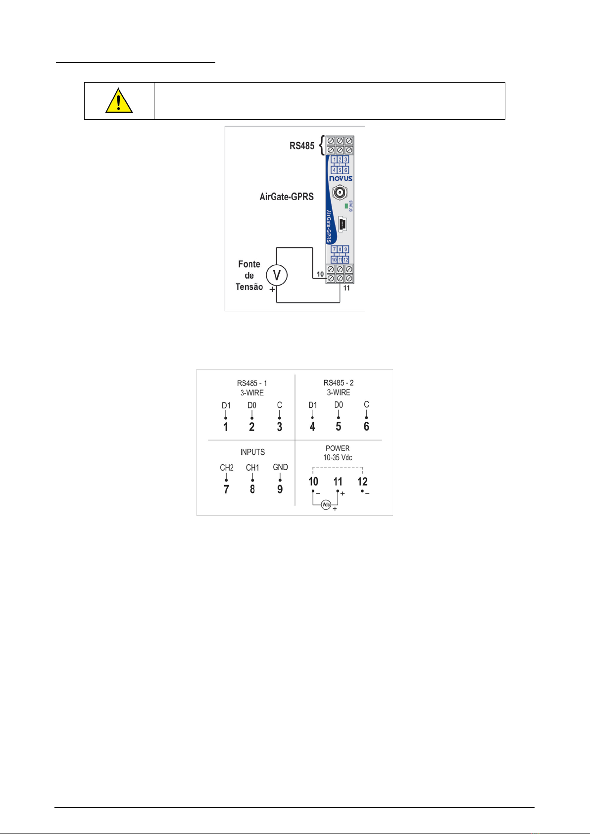
POWER SOURCE...................................................................................................................................................9
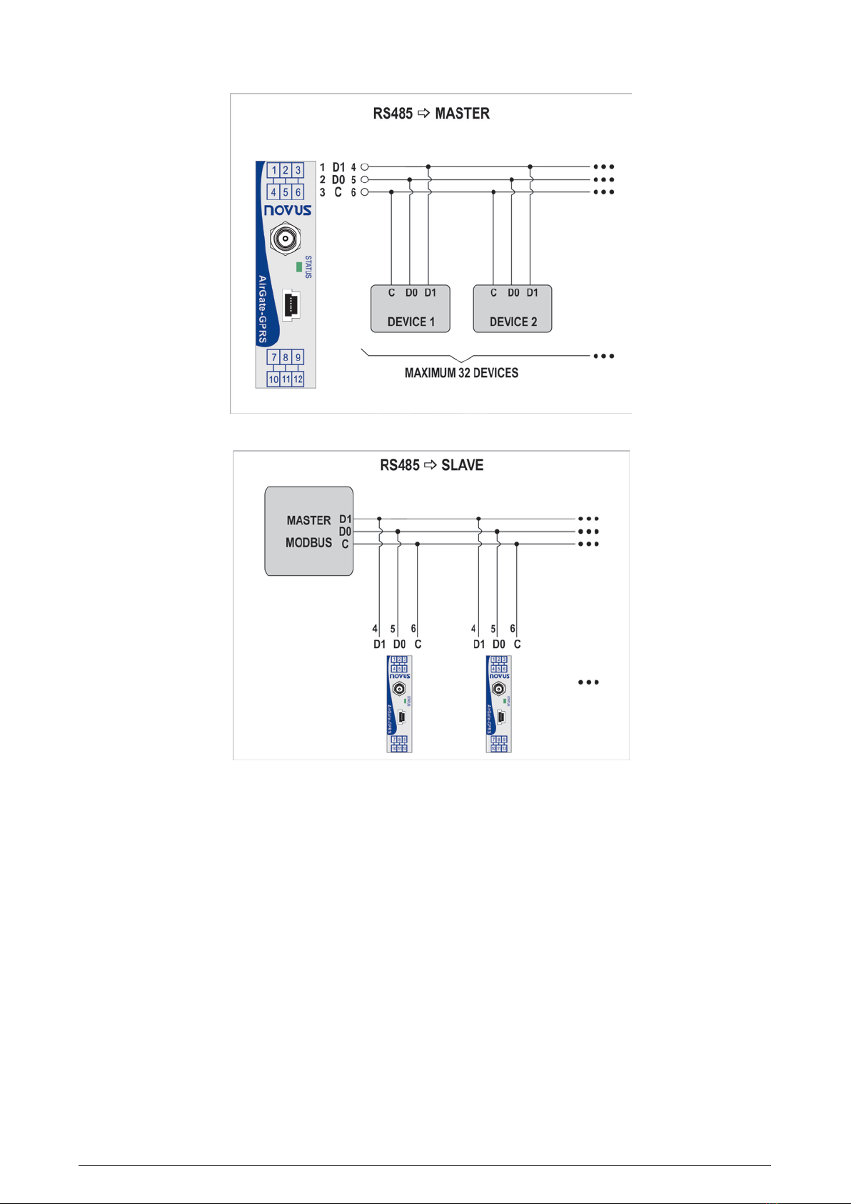
RS485...................................................................................................................................................................... 9
INPUTS.................................................................................................................................................................. 11
USB INTERFACE .................................................................................................................................................. 12
GPRS INTERFACE ............................................................................................................................................... 12
SIGNAL LIGHT (LED)....................................................................................................................................................... 13
USB DRIVER INSTALLATION.......................................................................................................................................... 14
WINDOWS 8 ............................................................................................................................................................... 14
DEFINITION AND SELECTION OF SERIAL PORT (COM) - WINDOWS......................................................................... 19
CONFIGURATION SOFTWARE....................................................................................................................................... 20
EQUIPMENT SOFTWARE (FIRMWARE) UPDATE.................................................................................................... 20
AIRGATE-GPRS OPERATION......................................................................................................................................... 21
GPRS INTERFACE..................................................................................................................................................... 21
AUTHENTICATION AND OTHER DETAILS.......................................................................................................... 21
WITHOUT AUTHENTICATION........................................................................................................................21
OPEN AUTHENTICATION...............................................................................................................................21
NAP..................................................................................................................................................................21
ANALOG OR DIGITAL INPUT..................................................................................................................................... 21
RS485 INTERFACES.................................................................................................................................................. 22
RS485 - 1............................................................................................................................................................... 23
RS485 - 2............................................................................................................................................................... 23
REMOTE CHANNELS................................................................................................................................................. 23
USB INTERFACE........................................................................................................................................................ 24
SENDING SMS – ALARMS AND STATUS................................................................................................................. 24
ALARMS................................................................................................................................................................ 24
SMS EXAMPLES................................................................................................................................................... 25
DATA COMMUNICATION AND ROUTING................................................................................................................. 25
ROUTING .............................................................................................................................................................. 26
ONE RS485 MASTER INTERFACE ................................................................................................................26
TWO RS485 MASTER INTERFACES .............................................................................................................26
MODBUS COMMANDS AND REGISTERS TABLE.......................................................................................................... 27
SUPPORTED MODBUS COMMANDS ....................................................................................................................... 27
READ HOLDING REGISTERS – 03H ................................................................................................................... 27
WRITE SINGLE REGISTER – 06H ....................................................................................................................... 27
WRITE MULTIPLE REGISTERS – 16H................................................................................................................. 27
TABLE OF HOLDING REGISTERS ............................................................................................................................ 27
DETAILS ABOUT SOME REGISTERS....................................................................................................................... 28
REGISTERS 0 AND 1 - SERIAL NUMBER ........................................................................................................... 28
REGISTER 2 – FIRMWARE VERSION................................................................................................................. 28
REGISTERS 3 AND 4 – VALUE OF THE ANALOG/DIGITAL CHANNEL............................................................. 28
REGISTERS 5 TO 14 – VALUE OF REMOTE CHANNEL .................................................................................... 28

AirGate-GPRS
NOVUS AUTOMATION 2/29
REGISTERS 31 TO 45 – SIM CARD IDENTIFICATION ....................................................................................... 28
REGISTER 46 – GSM SIGNAL LEVEL................................................................................................................. 28
REGISTER 51 – STATUS 1................................................................................................................................... 28
REGISTER 52 – STATUS 2................................................................................................................................... 28
WARRANTY...................................................................................................................................................................... 29

AirGate-GPRS
NOVUS AUTOMATION 3/29
INTRODUCTION
Ideal for machine to machine (M2M) telemetric applications, the AirGate-GPRS allows for the supervision of a network
with Modbus serial communication for more than one master. One of the masters can be remote, communicating using a
TCP/IP connection on GPRS using the cloud. Another master can be locally connected supervisory software. The
second RS485 interface can be configured as a Modbus slave, allowing a third master, such as a local IHM, to access
the slaves, or as a Modbus master, allowing a new branch of the network with more slaves communicating. The routing
of Modbus packets between the interfaces ensures the original performance of the network, even with other
functionalities turned on. Besides the gateway functionality, the AirGate-GPRS signals monitored alarms of Modbus
registers of the slaves connected to one of the interfaces.
Internet or cell phone based services, like data communication and text messages, are
subject to failures, delays and interruptions and do not offer any guarantees of success for
these services. Alway
s consider the failure possibility when specifying, designing or
building a monitoring, alarm or control system based on these services. NOVUS will not be
responsible for third-
party services that may be ceased or interrupted at any time, and it
cannot gua
rantee their integrity or availability for any period of time. The usage of such
services can generate exceeding costs, according to the one hired with the service
provider. NOVUS will not be responsible for any fixed or additional costs referring to any
service usage.
Avoid using prepaid and pay-per-use plans, either for data or text-messaging, since these
plans can bring severe performance limitations that are not easily predicted.

AirGate-GPRS
NOVUS AUTOMATION 4/29
TYPICAL APPLICATIONS
Below are examples of some AirGate-GPRS applications:
1. Remote monitoring without local monitoring
With this application, the AirGate-GPRS allows remote access to the data of the Modbus RTU network using the cellular
network (GSM/GPRS) and the sending of alarm and status messages (SMS).

AirGate-GPRS
NOVUS AUTOMATION 5/29
2. Remote monitoring with local monitoring
In this application, AirGate-GPRS is inserted in a Modbus network that needs local supervision (often it is an existing
Modbus network). Besides performing the role of a USB-RS485 converter, it allows remote access to data from the
Modbus RTU network using the cellular network (GSM/GPRS) and the sending of alarm and status messages (SMS).

AirGate-GPRS
NOVUS AUTOMATION 6/29
3. Remote monitoring with double local monitoring
In this application, the AirGate-GPRS is inserted into a Modbus network that needs local supervision of two Modbus
masters: normally a Supervisory software (SCADA) and an IHM or local CLP. Not only does it allow for the use of two
masters in the same network due to the capacity for routing the packets, it allows for remote access to data of the
Modbus RTU network using a cellular network (GSM/GPRS) and the sending of alarm and status messages (SMS).
4. Remote monitoring using only SMS
In this application, the AirGate-GPRS can either be or not be inserted in a Modbus network. The monitoring of the
desired variables is made only by text messages that state the periodic status of a few variables and alarm type
conditions.

AirGate-GPRS
NOVUS AUTOMATION 7/29
SPECIFICATIONS
Power Supply: 10 to 35 Vcc. Maximum consumption: 150 mA @ 24 V.
Environmental Conditions: Operation Temperature: -10 to 50 °C. Relative Humidity: 80 % up to 30 °C. For
temperatures higher that 30 °C, lower 3 % per °C.
Internal use.
Installation category II.
Pollution level II.
Altitude < 2000 m.
Dimensions:114 x 99.5 x 17.5 mm
Weight:
•Without antenna: 114 g
•With antenna: 174 g
Enclosure: PA66, with metallic attachment for 35 mm DIN track.
Internal protection against polarity inversion of the power supply voltage.
Wire section used: AWG 28 a 12.
Recommended torque: 4 kgf·cm.
Analog Entries:
The types of entry signals accepted by AirGate-GPRS and their minimum measurement bands are selected in the
Configuration software and are listed in the following table.
TYPE OF INPUT MEASUREMENT RANGE EXACTNESS
Linear 4 to 20 mA Configurable ± 1.0 % (F.E.) *
Linear 0 to 10 V Configurable ± 1.0 % (F.E.) *
F.E. = Scale Background = Span
(*) Note: he background scale is in regards to the input of the sensor’s signal and not the configured recommended range.
Table 01 – List of signals accepted by AirGate-GPRS
Although the analog inputs can recommend a bit beyond the limits of the configured range, the specification is not
guaranteed outside the range.
Impedance of the analog channel input:
•mA: 150 Ω + 1.5 V
•V: 670 kΩ
Digital Entries:
•Logical level “0”: from 0 to 0.8 Vdc
•Logical level “1”: from 2 to 6 Vdc
GPRS Interface:
GSM/GPRS Technology, class 8 to 12 (GRRS device class B)
Quad Band GSM operation range (850 MHz, 900 MHz, 1800 MHz and 1900 MHz)
Output power:
•1 W (GSM 1800/1900)
•2 W (EGSM 850/900)
RF Tx Power: +30 dBm
RF Rx Sensibility: bether than -100 dBm
Output for antenna GSM: impendency 50 Ω, SMA plug
USB Interface:
Mini-B type USB connector. Compatible with USB 3.0, 2.0 and 1.1.
Isolation of 600 V between the USB interface and the rest of the circuit (power, RS485 and analog/digital inputs).
Certifications: ANATEL (1534-13-7089)

AirGate-GPRS
NOVUS AUTOMATION 8/29
CONNECTIONS AND INSTALLATION
MECHANICAL INSTALLATION
The AirGate-GPRS has its own cabinet to be installed on a 35 mm track.
For the installation on the track, the metallic hook should be placed on the base and pressed against the track.
DIMENSIONS
Fig. 01 – Dimensions of the AirGate-GPRS
OPENING THE AIRGATE-GPRS
In order to open the AirGate-GPRS, you must press the orange lockers located on both sides of the enclosure and pull
the frontal cover very carefully, just like shown in Fig. 02.
Fig. 02 – Opening the AirGate-GPRS

AirGate-GPRS
NOVUS AUTOMATION 9/29
ELECTRICAL INSTALLATIONS
The AirGate-GPRS has power source connectors for inputs and RS485 serial communication interfaces.
Be careful when connecting the power source wires to the AirGate-GPRS
. If the
positive conductor of the power source is turned on, even for an instant, to one of the
communication connection terminals, the AirGate-GPRS can be damaged.
Fig. 03 - Power source and communication connections of the AirGate-GPRS
Fig. 04shows the required electrical connections. Terminals 1, 2, and 3 belong to the first interface RS485/Modbus
(RS485-1), while terminals 4, 5, and 6 belong to the second interface RS485/Modbus (RS485-2). Terminals 7, 8, and 9
are for the inputs (analog or digital) of the equipment. Terminals 10, 11, and 12 are used to feed the AirGate-GPRS.
Fig. 04– Electrical connections of the AirGate-GPRS
INSTALLATION RECOMMENDATIONS
•Input conductors should travel the system plant separately from the output and supply conductors, in grounded
electrical ducts.
•The power source of the instruments should come from a network that is appropriate for the instrumentation.
•The use of RC FILTERS (47 Ωand 100 nF, in series) parallel to the contactor coils and solenoids that are near or
connected to the equipment is recommended.
•In control applications, it is essential to consider what can happen when any part of the system fails. The relays of
output RL1 and RL2, used as alarms, do not guarantee total protection.
•Section of used wires: minimum gauge of 0.14 mm².
POWER SOURCE
Terminals 11 and 10 must be connected to the AirGate-GPRS power supply. Power supply polarity should be noticed.
RS485
The RS485 interfaces of the AirGate-GPRS have terminals for communication with 3 wires, including the common. The
wiring to the Modbus networks will depend whether each interface is configured to operate as a master or slave.

AirGate-GPRS
NOVUS AUTOMATION 10/29
•Master
•Slave

AirGate-GPRS
NOVUS AUTOMATION 11/29
INPUTS
There are two input channels that can be individually configured using internal jumpers such as input 4-20 mA, input 0-10 V
or digital input. There is no insulation between channels.
The jumper access requires the opening of the AirGate-GPRS. Their location can be seen in the following illustration:
*The AirGate-GPRS is factory configured as a digital input in both channels.
Digital Signal Wiring
When configured as a digital input, it can be connected to a voltage output (check the acceptable levels in the
Specifications section), a dry-contact output or a NPN output. Be careful when connecting multiple outputs due to the
lack of insulation between the AirGate-GPRS inputs.
Fig. 04 - Voltage connection Fig. 05 – Dry-contact connection Fig. 06 – NPN connection
Connection Current (mA)
Channels connection in the terminals should be done as shown in the figure on the left.
Check the correct connection polarity.

AirGate-GPRS
NOVUS AUTOMATION 12/29
Voltage connection (V)
Channels connection in the terminals should be done as shown in the figure on the left.
Check the correct connection polarity.
USB INTERFACE
The AirGate-GPRS has a USB interface that can be connected to a computer for configuring or monitoring. The USB
cable is supplied along with the equipment.
GPRS INTERFACE
This interface requires a compatible antenna, supplied with the equipment, to be connected at the external SMA plug.
Internally, the user should insert a SIM card from any operator in the corresponding connector.
Never remove or insert a SIM card from the AirGate-GPRS while it is turned on.

AirGate-GPRS
NOVUS AUTOMATION 13/29
SIGNAL LIGHT (LED)
Signal for GPRS Connection Status:
Upon powering on the equipment, the led remains turned off until the start-up is completed. The signal will occur in the
following manner:
•The led will flash slowly during the GSM network access process;
•The led will flash rapidly when it connects to the GSM network;
•The led will flash twice rapidly when the connection with the remote server is established.
After powered, AirGate-GPRS led can take a few seconds to start flashing!

AirGate-GPRS
NOVUS AUTOMATION 14/29
USB DRIVER INSTALLATION
In order to use the USB interface of the AirGate-GPRS (so you can configure the equipment with the configuration
software, for example), it is necessary to install its USB driver. The installation steps can vary from computer to
computer, between different operating systems, and even between one version and another of the same operating
system.
Windows 8 (64 bits) does not allow the installation of drivers that are
not “digitally signed” by Microsoft.
Thus, before installing the USB drivers of the AirGate-GPRS, the following script should be followed:
1. During the boot, you should press the F8 key to enter the Start-up Configurations.
2. Pressing the F7 key, you can disable the Imposition of the Driver Signature.
3. Windows 8 will now allow you to install the USB driver for AirGate-GPRS.
Following are the steps and guidance screens for the driver installation.
WINDOWS 8
1. Connect the AirGate-GPRS in a USB port on your computer. Windows will try to install a driver automatically and will
not succeed, because the necessary driver is not in its standard library.
2. On Desktop screen, right-click on the left-bottom corner of the screen and choose the "Control Panel" option. Then
choose the “System and Security” option, then the "System" option and, at last, "Device Manager".

AirGate-GPRS
NOVUS AUTOMATION 15/29
3. Locate the AirGate-GPRS (probably with an icon with an exclamation mark next to it) and double-click on it.
4. Click on the button "Update Driver...".

AirGate-GPRS
NOVUS AUTOMATION 16/29
5. Ask to "Browse my computer for driver software".
6. Enter the path of the folder where the drivers are located (the product CD or folder where you saved them when
downloaded from the site.)

AirGate-GPRS
NOVUS AUTOMATION 17/29
7. Wait for the installation to take start.
8. Windows will indicate that it cannot verify the editor of this driver. Confirm to install anyway!

AirGate-GPRS
NOVUS AUTOMATION 18/29
9. A message indicating successful installation will display.
10.Returning to the Device Manager screen, you can check which virtual serial port is allocated to the AirGate-GPRS.

AirGate-GPRS
NOVUS AUTOMATION 19/29
DEFINITION AND SELECTION OF SERIAL PORT (COM) - WINDOWS
The serial port associated with AirGate-GPS is automatically defined by the operating system a few moments after
connecting the AirGate-GPS. The user can easily identify or change the COM port associated with AirGate-GPS:
Control Panel / System / Hardware / Device Manager / COM & LPT Ports
Select the device "USB Serial Port" corresponding to the AirGate-GPS and click on "Properties". Select "Port Settings"
guide and click on "Advanced". In the "COM Port Number", select the serial port to be associated with AirGate-GPS.
Some serial ports can be checked while being used (In Use). Just select one of these ports if you know that it is not
being used by another peripheral device on your computer.
In some cases, the serial ports can be checked as in use even when the associated device is no longer installed on your
computer. In this case it is safe to associate this port to AirGate-GPS. The following figure presents the view of the
device manager containing a AirGate-GPS, and the screens showing the property screens where you can reset the
associated COM port.

AirGate-GPRS
NOVUS AUTOMATION 20/29
CONFIGURATION SOFTWARE
The software used for configuration of the AirGate-GPRS is the DigiConfig (version 1.6 or higher). Besides the
configuration, it allows the verification of the input channel Reading and provides status information. This software is
supplied for free with the product CD and can also be downloaded at the manufacture’s website. Checking for updates
from time to time is recommended.
DigiConfig has a full help file with all of the necessary information for its complete usage, including the correct
configuration of the product configurations. To consult it, start the application and select the “Help” menu, or press the
“F1” key.
To begin configuration of the AirGate-GPRS, connect it to the computer (via USB or RS485) and select the
“Communication” option on the “Configuration” menu. In the window that appears, select the correct serial port and
configure the other communication parameters. After applying the communication configuration, the system is ready to
read the the AirGate-GPRS configuration by clicking on the Search button located in the lower left corner of the main
window. In order to make the search faster, configure the Modbus address range to search correctly (do NOT use
“Temporary” option for AirGate-GPRS). If you know the Modbus address of the interface on which you are connecting
(USB or RS485), check only the “First Address” and enter the right address on this field. Once the equipment is
identified, it is shown on the list on the left. Clicking on it will display its configuration on the right side.
The configuration of the device is divided by functionality in several tabs. The choice of some options can affect the
limitation or absence of other configuration parameters. Last of all, the configuration should be applied to the equipment
using the Apply button.
The use of the AirGate-GPRS with all of its functionalities is described in the chapter “AirGate-GPRS Operation."
EQUIPMENT SOFTWARE (FIRMWARE) UPDATE
AirGate-GPRS can update its internal software (firmware), allowing the benefits of new versions with new characteristics
or important improvements to be accessed without needing to send the equipment to technical assistance.
The latest update is available for download on the manufacturer website. The update process is done by DigiConfig,
using the related tab.
Table of contents
Other Novus Network Router manuals
Popular Network Router manuals by other brands

Digisol
Digisol DG-BG1100U user manual

Mellanox Technologies
Mellanox Technologies PowerEdge M420 user manual

Lancom
Lancom 3550 Wireless user manual

Beamz
Beamz DMX-240 Controller 192-Channel instruction manual

Planet Networking & Communication
Planet Networking & Communication FNSW-1601 instruction manual

Xiaomi
Xiaomi Mi Router 4A Gigabit Edition user manual

D-Link
D-Link DIR-882 user manual

Atlantis Land
Atlantis Land I-Fly A02-WRA-11B Specification sheet

ZyXEL Communications
ZyXEL Communications ARMOR G5 quick start guide

SMC Networks
SMC Networks Barricade SMC7401BRA user guide

Allied Telesis
Allied Telesis AT-8000S Series user guide

Repotec
Repotec Powerline 85M user manual