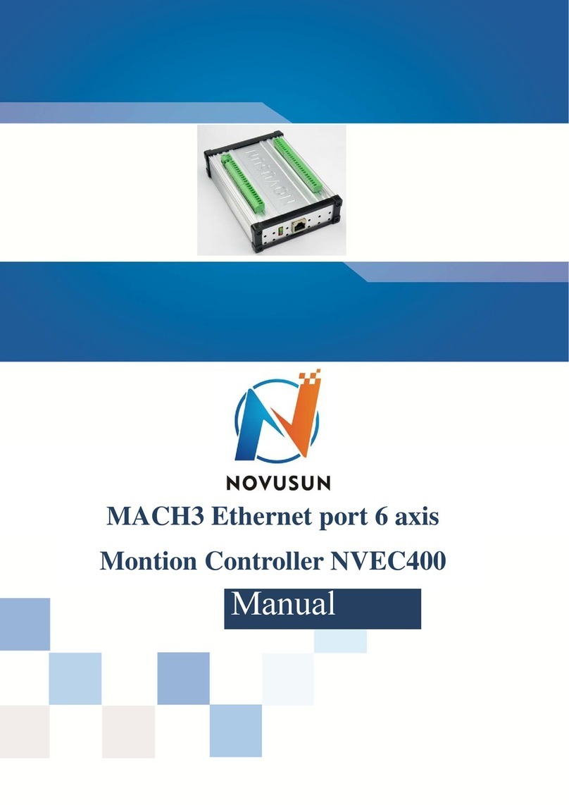
Novusun CNC NVEMV1.1 User manual

M
Manual of NVEMv1.1
contect
Chapter1 Introduction..............................................................................................................................................1
1.1. ProductIntroduction............................................................................................................................ 1
1.2. Productsspecification.......................................................................................................................... 1
1.3. ProductsAppearance and struction and size....................................................................................... 2
1.4. substantivalexplanation....................................................................................................................... 3
1.5. Noting andWaring............................................................................................................................... 5
Chapter2 Connection...............................................................................................................................................6
2.1. Device PowersupplySolution............................................................................................................. 6
2.2. Productconnection define and method................................................................................................ 7
Chapter3 Software Installation..............................................................................................................................21
3.1. MACH3 Install.................................................................................................................................. 21
3.2. MACH3Registration.......................................................................................................................... 24
3.3. NVEMPlug-in installation................................................................................................................ 24
Chapter4 Usingofsoftware...................................................................................................................................25

C
hapter 1 Introduction
Chapter1 Introduction
1.1. ProductIntroduction
Novusun CNChas engagedintheNumericalcontrolindustryfor4 years,specializedin
theresearch,developmentand production ofvarious CNCcontroller systemswithhighquality
and highreliability.Weproduce theBrushless DCmotor,Stepper motordriver,and also 1to6aixs
CNCmotion controllers.。
NVEMv1.1 is the3-6 axis motion controller wespend 4 years to design.
NVEMv1.1 supportMach3 software and standardMPG,throughEthernetto
communicatewith computer,justusetheTwinetoconnectdirectlyortransfer with router.
NVEMv1.1 motion controller adoptstheARMdesignframework.TheARMdesign
includescommunication,codeanalytic,underlyingalgorithmand pulsegerneration. Rational
design,reliablecontrol,convenientoperation.
Thismanualintroducesoperation,connection andusagescheduleofourprofessional
motion controller forengravingmachine.Through alotofthedrawingtheuserscanlearn
quicklyhowto usethismotion controller.
1.2. Products specification
S12 ports photoelectricisolated inputinterfaceforordinarydigitaldata;
S10 ports photoelectricisolated outputinterfaceforordinarydigitaldata;
S1 port0-10Vspindlespeed analogoutputinterface(canchangeto PWM output);
Scan support3-6axis stepper systems,200KHzpulseoutputforeveryaxis;
SARM motion controlchip;

C
hapter 1 Introduction
Smain device is 12V-32VDCpower supplyinput,currentshould higher than0.5A;
SCompatiblewithMPGinput,supportthedigitaldisplayMPGfromourcompany。
1.3. ProductsAppearance andstruction and size
■NVEMv1.1 motion controller iswiththesealedshell structure,thereare4pcssetting
holes atthebottom.Wecan fix4pcs 4mm diameterholes atthecabinet,and install thecontroller
into thecabinet.Thecontroller appearance as theFigure 1-1and Figure 1-2 show:
Theproducts overall sizeis 163.1mm*80.8mm*27.8mm;
Thebottominstall sizeis101.4mm*42.5mm。
Figure 1-1. NVEMV1.1 frontappearance and size

C
hapter 1 Introduction
Figure 1-2. The othersideofNVEMV1.1and installation dimensions
1.4. substantival explanation
WhenoperatetheNVEM,where will bealotofEnglish abbreviation,nowwelistall of
themforyourkindlyreferences:
FRO:Feedingadjust:Duringtheoperating process,theFvaluealreadyset,and needto
adjustthecurrentfeeding speed, then wecanadjustFROvalueto realizeit.
SRO:Spindlespeedadjust: Duringtheoperatingprocess, theSvaluealreadyset,and need
to adjustthecurrentspindlespeed, then wecanadjustSROvalueto realizeit :
CurrentSpeed S#=settingS*SRO.

C
hapter 1 Introduction
SRJ:speed adjustmanually
During theoperatingprocess,asthemanualspeedalreadyset,and weneedtoadjustthe
currentspeed,and impossibletofixthevalueduringit isworking,thenwecanrevisetheSRJ
valueto realizeit.
Currentmanualspeed FS#=Settingmanualspeed*SRJ.
F:Feedingspeed,theunit ismm/min.ForexampleF=200,meanseveryminutefeeding
2000mm.
S:SpindleSpeed. Unit israd/min.ForexampleS=20000,means 20000 revolution/Minute.
Xaxis Coordinate
Yaxis Coordinate
Zaxis Coordinate
Aaxis Coordinate
Baxis Coordinate
Caxis Coordinate
Ready:ReadyMode.Inthemodewecando anyoperation,includeprocessingorvalues
modification orstarting2nd mode.
Reset: Resetmode.In this mode,it should stop everyoperation.
Step”:ManualStepMode.Every axiscandonductthemanualstepoperationatthismode.
MPG:MPGmode.Everyaxis can conducttheMPGoperation atthis mode.

C
hapter 1 Introduction
1.5. Noting and War
ing
Freefrom
exposure totheelectronicswithoutwaterproof
function.Pleaseenvironme
ntas dryas possible.This is theicon.
Wiringwar
ning, theIOinputterminalofthis equipmentsupportthe
equipmentwith source sw
itch(suchasInductiveproximityswitch.)Whenusing
suchkind ofswitch,
attention please:avoidthe+terminaland
po
wer supplytoconn
ect
outputterminalofspind
lecontrolalos haveacertainloadcapacity.Pleaseavoid
thisterminalconnectwit
h GND.in casethattheinteriorcomponents and parts be
brokendown.
Operation w
arning, Plea
connectingwiththemachi
netools.TheESTOP,limit and other things mustbe
p
erfected.Whencomes
across theemergancy,pleasepress theESTOPkeyatonce
orcutoffthepowerdirec
tly,thus avoidingthee
High volta
gedanger, theprimarydeviceis 18
supply.Voltageequipment.
Pls payattention to theelectricity, safetywhen conducting
theoperation
Noting and Wari
ng
Freefrom
exposure totheelectronicswithoutwat
erproof
function.Pleaseenvironmen
tas dryas possible.This is theicon.
rn
ing, theIOinputterminalofthis equipment
supportthe
equipmentwith source swit
ch(suchasInductiveproximityswitch.
)Whenusing
suchkind ofswitch, a
ttention please:avoidthe+terminaland
–
power supplytoconnec
twithGND.Thisequipment’sanalogyq
uantity
outputterminalofspindl
econtrolalos haveacertainloadcapacity.
Pleaseavoid
thisterminalconnectwith
GND.in casethattheinteriorcomponents
and parts be
Operation w
arning, Pleasedo thesecuritymeasures well w
hen
connectingwiththemachin
etools.TheESTOP,limit and other thi
ngs mustbe
perfected.Whencomesacr
oss theemergancy,pleasepress theESTO
Pkeyatonce
orcutoffthepowerdirect
ly,thus avoidingtheequipmentdamageand
casualty.
High voltag
edanger, theprimarydeviceis 18-32VDCpo
wer
supply.Voltageequipment.P
ls payattention to theelectricity, safetywhen
conducting
Freefromexposure totheelectronicswithoutwater
proof
rning, theIOinputterminalofthis equipmentsuppo
rtthe
equipmentwith source switch(suchasInductiveproximityswitch.)W
henusing
–
terminalof
withGND.Thisequipment’sanalogyqu
antity
outputterminalofspindlecontrolalos haveacertainloadcapacity.
Pleaseavoid
thisterminalconnectwith GND.in casethattheinteriorcomponents
and parts be
sedo thesecuritymeasures well wh
en
connectingwiththemachinetools.TheESTOP,limit and other things
mustbe
perfected.Whencomesacross theemergancy,pleasepress theESTO
Pkeyatonce
quipmentdamageand c
asualty.
32VDCpow
er
supply.Voltageequipment.Pls payattention to theelectricity, safetywhen c
onducting

C
hapter 2 Conection
Chapter2 Connection
2.1. Device PowersupplySolution
Thepower supplysolution inthefieldoftheIndustrialautomation isalwaysvery
complicated,thereisalotoftheGND,nowwedescriptthestructure ofthepower supply asbelow:
Thepower supplystructure astheFigure 2-1,mainpower supplyinputand MPGmoduleand
stepper controloutputmoduleare common GND,Limitedand Estop inputmoduleand Spindle
speedadjustM3/M8/M1 modulearecommon GND,betweenmainpower supplyand output
modulethere arephotoelectricisolation.Theinputsoflimitedswitchand Estop and so on are
Common anode,insideofthedevice,thereis+12VDCascommon+,no needtoconnectexternal
power supply. BasedonthereferenceofoutputGND interface,outputa0-10Vadjustablevoltage
toadjustthethespindlespeed,M3/M8/M10 digitaloutputinterfaceisopen-GND.Ifconnectan
externalrelay,need to outputGND to refer to,and givetherelayan externalpower supply.
Figure 2-1. Powersupplystructure

C
hapter 2 Conection
2.2. Productconnectiondefine andmethod
Figure 2-2. Productwiring section andinterface summary
AstheFigure 2-2showed,theconnection ofthecontroller includespower supply
interface,Ethernetconnection interface,MPGinterface,Stepper/Servocontroloutput
interface,spindlecontroloutputinterface,Estop and limitedswitchand toolsetting inputinterface
and so on. Nowwedescriptthemin details as below.
2.2.1 Steppermotor control interface
AsFigure2-2showed,No.1 terminalblockis6axisstepper drivercontroloutputinterface,
fromlefttoright,there areX,Y,Z,A,,B,C6axisoutput,it’scommon anode,thecableconnection for
eachaxisisCOM+/CP-/DIR-,COMiscommon+,CPisPulse-,DIRisdirection-.Connection
showed as Figure 2-3.COM+connectwith theSP+and DIR+.
Pin mark Axis Definition
COM+ Commom+ common anode+5V

C
hapter 2 Conection
CPX- Xaxis Pulseoutput-forXaxis
DIX- X axis Directrion output-forXaxis
CPY- Y axis Pulseoutput-forYaxis
DIY- Y axis Directrion output-forYaxis
CPZ- Z axis Pulseoutput-forZaxis
DIZ- Z axis Directrion output-forZ axis
CPA- A axis Pulseoutput-forAaxis
DIA- A axis Directrion output-forAaxis
CPB- B axis Pulseoutput-forBaxis
DIB- B axis Directrion output-forBaxis
CPC- C axis Pulseoutput-forCaxis
DIC- C axis Directrion output-forCaxis
Table 2-1 Stepper drivercontrol interface define

C
hapter 2 Conection
Figure 2-3. Stepper driverconnection
2.2.2 Spindle control output
Wedefinetheinterface fromleftare:GND1(OutputGND),VSO(0-10Vadjustablespeed
output),INDEX(spindlespeedfeedbackinput),OUT1(common outputport1),OUT2(common
outputport2),.
TakeNowforeuerinverterastheexample.Spindlecontroloutputand theinverter connection
showed as Figure 2-4.IfACM and DCM are closed,onlyneed to connectoneport.
IfneedtheMach3toshowtherealintimespindlespeed,justfixonehall device,every
revolution send onepulsebetweenINDEXand GND1,pulsevoltageis 5V-10V.

C
hapter 2 Conection
Figure 2-4. spindle controloutput andinverterconnection
VSOrealoutputvoltage=10V*s spindlesettingspeed/maxspindlespeed.Forexample,ifmax
spindlespeedis24000,currentspindlespeedisS=18000,so theVSOoutput
voltage=10*18000/24000=7.5V.
Max.spindlespeedsettingportsasshowedsaFigure2-5,openit fromPulleyfromMenu
config.ThecurrentspindlespeedcanbesetbySdirectiveorMach3spindlesettingspeedmodule.
Figure 2-5. Max spindle speed setting position

C
hapter 2 Conection
2.2.3 Common IOoutput interface
Common IOoutputincludeOUT1,OUT2 on thespindleinterface,totally10 portsIO
output,open drainoutput,internalstructureas Figure2-5..
Figure 2-6. OUT1-OUT10internal structure
NowjustmakeaswitchbetweenOUTX(X=1-10)and GND,tocontroltherelay
output,theconection astheFigure 2-6.Externalpower supplyneedtoaccordwiththerelay
specification,theinternaloptocoupler GND opencircuit onlycanabsorbless than50mAcurrent,if
relayabsorbthecurrentover 50mA,plsadd currentamplifier.IntheFigure connectwithOUT3,the
others similar.

C
hapter 2 Conection
Figure 2-7. OUTX connect with external relay method
2.2.4MPG connection
TheMPGporttotallyhave18 wiringterminals, and thereference ofeachwiring
terminaldefinition istable2-2. Thereferenceofcorrespondingrelationbetweensystemand
MPGwiringis table2-3and table2-4.
Pinmark Definition Notes
GND MPG Ground MPG power supply GND.
TXD MPGserialcommunication
OutputPort
Forthe digitaldisplayMGPcommunication
RXD MPGserial
communicationinputPort
Forthe digitaldisplayMPGcommunication
100X 100X multiplication
switch
shortconnectwith GNDmeans100X
multiplication,cutoffmeansno pulse
10X 10X multiplication
switch
shortconnectwithGND means10X
multiplication,cutoffmeansno pulse

C
hapter 2 Conection
1X 1 X multiplication
switch
shortconnectwithGND means1X
multiplication,cutoffmeansno pulse
ESTOP MPG Estop shortconnectwith GNDmeansEstop
effective,cutoffshowinvalid
C-IN CAxisselected switch Shortconnectwith GNDmeanasselectingC
aixs,cutoffmeansdont select
B-IN BAxisselected switch ShortconnectwithGND meanasselectingB
aixs,cutoffmeansdont select
A-IN AAxisselected switch Shortconnectwith GND meanasselecting A
aixs,cutoffmeansdont select
Z-IN ZAxisselected switch Shortconnectwith GND meanasselecting Z
aixs,cutoffmeansdont select
Y-IN YAxisselected switch Shortconnectwith GNDmeanasselectingY
aixs,cutoffmeansdont select
X-IN XAxisselected switch ShortconnectwithGND meanasselectingX
aixs,cutoffmeansdont select
VDD5 MPGpowersupply5V
output
MPGpowersupply5Voutput
WHA+ MPG A Phases Positive MPG A Phase differential Input Positive
WHB+ MPG B Phases Positive MPG B Phase differential Input Positive
WHA- MPG A Phases Negative MPG A Phase differential Input Negative
WHB- MPG B Phases Negative MPG B Phase differential Input Negative
Table 2-2 NVEM on MPG’sdefine and explaination

C
hapter 2 Conection
NVEMPINNo. MPGpinNo. and color
Estop C Lightblue
1multiplication 1 X1 grey
10multiplication 10 X10 Black/Grey
100multiplication 100 X100 Orange
Xselecting X Yellow
Yselecting Y Black/Yellow
Zselecting Z Brown
Aselecting 4 Black/Brown
Bselecting 5 Pink
Cselecting 6 Pin/Black
APhase + A+ Green
APhase - A- Purple
BPhase + B+ White
BPhase - B- Purple/Black
GND 0V/CN/COM Black,Black/light
blue,black/orange
+5V-W +5V red
Table 2-3 ConnectionbetweenDifferential MPG and NVEM
Note:Ityou wanttousethesingle-terminalMPG(namelythereisno A-B-MPG),please
look atthewiringtable,thetable2-4forreference.Asfortheunlistedone,pleasetakethe
differentialMPGwiringmode.

C
hapter 2 Conection
NVEM PinNo. MPG Pin No. and color
WHA+ A+ green
WHA- 0V Black
WHB+ B+ white
WHB- 0V Black
Table 2-4 ConnectionBetweenSingle MPGandNVEM
2.2.5 Main power supply input Interface
AstheFigure2-2show,No. 5positioninterface isthemainpower supplyinput,marked +”is
thepower supplypositive,theother onewasn’tmarkedisthenegative,power supplyvoltageis
12-32VDC,Currentmustbenotless then 1A.
2.2.6 Commnicationexternal interface
AstheFigure2-2showed,themarkedNo. 6position iscommunication externalport,thisport
wasn’tdefinedyet.
2.2.7Estop limitedTool setting input interface
.AstheFigure2-2showed, MarkedNo. 7position istheEstop limitedect.theyare the
opticalisolatedInputinterface,fromtheleft,thereare12V,STOP,12V,PROB,12V,INP3,INP4,INP5,
INP6,INP7,12V,INP8,INP9,INP10,INP11,INP12,GND.Here STOPisINPUT1 ,and PROB
isINPUT2. Internalstructure FigureofInputinterface see as Picture 2-8
ESTOPconnectwith NVEM see as Picture2-9.

C
hapter 2 Conection
Figure 2-8. Internalstructure drawing ofInputinterface
Figure 2-9. Estop input connection
ToolSettingConnection see as Picture 2-10

C
hapter 2 Conection
Figure 2-10. ToolSetting Connection Drawing
2 lines ProximitySwitch/ordinaryfrettingswitch drawingsee as Picture 2-11
Figure 2-11. 2 linesProximitySwitch/ordinaryfrettingswitch drawing
3 lines ProximitySwitchconnection Figure2-11,brown cableforProximityswitch connect
with 12V,Blackcableconnectchannel,bluecableconnectwith GND1.

C
hapter 2 Conection
Figure 2-12. PNP3 linesProximitySwitch connection drawing
2.2.8 Parameteradjust interface
Bythis adjustinterface,user can useamuti-position switch and adigital
potentionmeter(simpleencoder) to modifyFRO,SROand SJR.Wiringmethod see as figure2-13
simpleencoder's COMABconnectto 12V/FHA/FHB,and muti-position switch connectto 12V
SROSJR.If12Vdon'tconnectto SROorSJR,currenteffectiveparameter isFRO, if12Vconnect
to SRO,currenteffectiveparameteris SRO,and if12Vconnectto SJRcurrenteffectiveparameter
is SJR.
Table of contents
Other Novusun CNC Network Hardware manuals

