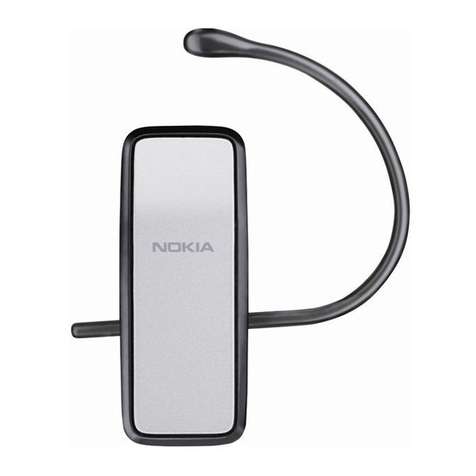
Now Technologies Switch-It Vigo User manual

Switch-It®Vigo
Head Drive & Head Mouse
INSTALLATION GUIDE
Document identifier: NOW.Q.CE.M.EN-SIV-0002-01
Revision: 01
Date of issue: 26 June 2023
©2023 NOW technologies Ltd. All rights reserved.
European representative of the Manufacturer:
NOW technologies Ltd., 18. Reáltanoda street, Budapest, 1053 Hungary
www.nowtech.hu

⚠
Caution
⚠
3
Preparations 3
What’s in the box 3
First steps of installation 4
System connection diagram 4
Assembly of the Vigo headset 4
Fitting the Headrest Sensor 5
Headrest Requirements 7
Setting up with visual feedback 9
Accessories needed for this setup: 9
1. Screw the Cubo mount onto the back of the Omni mount 9
2. Secure the Link to the back of the chair 10
3. Connect Link and Cubo 11
Connect Link and Cubo with the microUSB to microUSB cable provided. 11
Certain conditions can affect the operation of the Vigo: 12
Setting up with audio feedback only 13
When to use this? 13
Secure the Link and the Cubo in the Omni 2 bag 13
Final steps 14
Fasten all loose cables to the appropriate parts of the frame 14
Revision History 15

⚠
Caution
⚠
The Switch-It® Vigo Head Drive components may only be installed by a dealer authorized
and trained by NowTechnologies/Sunrise Medical. The dealer carries out the assembly
according to the instructions given on the installation training. Incorrect installation might
have an adverse effect on performance and will invalidate warranty.
Preparations
Prepare the following materials and tools:
● Powered wheelchair using the R-net system, equipped with an Omni 2 speciality
control interface
● Switch-It Vigo Head Drive
● Either an Omni 2 Cubo mount OR a Sedeo Pro Advanced Omni 2 Bag Mounting
● Cable ties
● Plier
● Allen key set
What’s in the box
- Link
- USB to micro-USB cable to charge the Vigo
- Dongle
- Vigo with plastic “C” mounting ring
- The headband of the Vigo
- Special Micro-USB to Micro-USB cable to connect the Link and the Cubo
⚠Please handle this cable with care!
Due to the nature of its placement, it can be damaged easily. If that happens, please contact
support and ask for a replacement.
Do not attempt to replace the cable with other Micro-USB cables! It is a crosslink cable
specially made for these devices.
- Cubo
- Headrest Sensor

First steps of installation
System connection diagram
Assembly of the Vigo headset
The Vigo headset comes with the so-called C-ring already on it. It provides a perfect fit for
the headset into the headband.
Make sure to check the C-ring's position every time you put the headset on the user, or
adjust the Vigo's position in the headband!
Please do not remove the C-ring from the Vigo!
Removing the C-ring may damage the device.

Grab the Vigo and the Headband and hold them between your thumbs and index fingers like
so:
Then, just pop the Vigo into the Headband by firmly pressing it over the GyroSet symbol.
Make sure you don’t apply pressure to the Multi-function button but the body of the Vigo as it
may damage the button.
To ensure the Vigo is securely attached in the headband, the open end of the C-ring should
always point towards the end or the back of the Vigo (i.e. the "mouth" of the C should be
perpendicular to the headband), otherwise, it can fall out of the headband.
Fitting the Headrest Sensor
Fasten the Headrest Sensor to the headrest of the chair using its velcro strap!
Make sure that the wiring meets the following criteria:
● The Headrest Sensor must be properly connected to Cubo.
○ The cable must be tied to the frame of the wheelchair to avoid accidental
tearing or crushing by the movement of actuators.

○ The cable placement has to be designed so that cables are protected during
accidental crashes if the wheelchair hits an obstacle.
● The Headrest Sensor must be tied to the headrest by the reusable tie and strap in a
way that it won’t move during extended periods of usage.
● Please make sure that the position of the Headrest Sensor is easy to reach by the
user.

Headrest Requirements
Suitable headrests must have a fairly hard foam density and a large enough flat or almost flat
surface space to accommodate the full size of the headrest sensor in its pouch. It can be
mounted on the outside of the headrest or placed under the removable cover of the
wheelchair’s headrest. The removable cover must be a tight fit around the headrest foam to
ensure the sensor is snug and tight between the surfaces to stop it from moving and keep it
secure.
An example of the ideal shape of the headrest:
Unsuitable headrests examples:
Very puffy and soft density foams that do not allow the sensor to operate at optimum
performance.
Headrests that are too curved or with too small a surface to accommodate the size of the
pouch or sensor alone.

Hard rubberized with deep curves and dips not allowing a flat enough surface for the sensor.

Setting up with visual feedback
Accessories needed for this setup:
● An Omni 2 Cubo mount:
● Two sets of bolts, that are provided with the Cubo mount:
○1 pair of 10mm long M4 bolts - these are for attaching the Cubo mount to the
Omni2 mount
Depending on the type of the Omni mount, you may need 16mm long M4 bolts
(e.g. Link-It mounting system)
○1 pair of 6mm long M4 bolts - these are for attaching the Cubo to the Cubo
mount
1. Screw the Cubo mount onto the back of the Omni mount
Use the longer bolts to secure the Cubo mount to the
Omni mount.

Then use the provided shorter (6mm long) bolts to
secure the Cubo itself onto the Cubo mount.
Do not use any other bolts to secure the Cubo
to the mount, as longer bolts may damage it!
● Devices that may produce radio interference,
such as Smartphones, Pagers, Bluetooth
devices must be kept out of the way and placed
at a distance from the Cubo.
● The Cubo should be placed so that the display
is visible for the user and the assistant/carer as
well.
● To take advantage of the IP54 protection of the
casing, cables must face the ground to prevent
rain getting into the connector.
● We recommend placing the Cubo on the same
side on which the user wears the Vigo.
● Please make sure that the placement of the
Cubo allows for protection against mechanical
damages (e.g. falling objects) for the display.
2. Secure the Link to the back of the chair
The Link enclosure has two M4 nuts at the back of the device that is designed specifically for
mounting. As every vehicle and user is unique there is no general mounting bracket
available.
Please make sure that the physical mounting meets the following criteria:
● To take advantage of the IP54 protection of the casing, cables must face the ground
to prevent rain getting into the connector.

● The Link’s mode selection touch interface (touch button with the logo) must be
accessible for the caretaker.
○ Devices that may produce high capacity charges, such as ionisators must be
at a safe distance from the touch interface to avoid accidental activation.
● The audible feedback of the Link is of high importance for the user, placement should
avoid blocking of the speaker.
● Please don’t exceed the minimum working temperature of -20°C and the maximum of
50°C of the Link
In case of using the Sedeo Pro Advanced Omni 2 Bag Mounting for the Omni 2, you can hide
the Link next to it with all its cables in the bag.
3. Connect Link and Cubo
Connect Link and Cubo with the microUSB to microUSB cable provided.
Do not attempt to replace the cable with other microUSB cables! It is a crosslink cable
specially made for these devices.
There are two connector interfaces on the Link.
One is an integrated cable with a D-sub type
connector on it connecting to the Omni.
This needs to be connected to one of the Omni 2
ports (preferably Port 1).
Another oval-shaped port is there to
connect the microUSB to microUSD
cable. The straight, oval shaped end of
this cable has to be plugged in, all the
way into the hole on the Link with the
USB sign facing down.
The other end of the cable connects to the Cubo, like so:

Headrest Sensor Connector
Link Connector
Certain conditions can affect the operation of the Vigo:
The Switch-It® Vigo Head Drive offers unprecedented freedom of movement by using
wireless radio communication. The operation can be disturbed in environments with
extremely high radio interference, which may result in a safety stop.
In such environments the cables may act as antennas, so the positioning of them matters
greatly.
In extreme cases we recommend the use of ferrite beads.
If you need help with the placement contact technical support.

Setting up with audio feedback only
When to use this?
This configuration is recommended in cases where a minimalist aesthetic is the goal and the
user is happy with audio feedback only or when the frame of the wheelchair amplifies
electromagnetic interference in a way that it cannot be counteracted otherwise.
The Sedeo Pro Advanced Omni 2 Bag Mounting provides protection against such
interference and prevents resulting inconveniences.
Secure the Link and the Cubo in the Omni 2 bag
1. Coil up both cables coming out of the Link: the integrated cable with the D-sub type
connector going into the Omni and the microUSB cable connecting to the Cubo.
2. Tie them up with a cable tie or a piece of velcro strap.
3. Hide them all next to the Omni 2 in the bag.
Caution! This solution may impair the audible feedback of the Link and block the
visual feedback of the Cubo.

Final steps
Fasten all loose cables to the appropriate parts of the frame
Fasten the Headrest Sensor and the Cubo-Link cables to fixed points of the wheelchair every
15 or so centimeters with a cable tie or a velcro strap.
Make sure to tuck those cables away from harm as much as possible. Cables sticking out to
the side may get damaged by getting caught during driving or transit.

Revision History
Revision number
Changelog
Date of release
01
Original content
26 June 2023
Other manuals for Switch-It Vigo
1
Table of contents
Other Now Technologies Headset manuals
