NPC Betta FLO BMLS-M Guide

Page 1
SELF-PRIMING CENTRIFUGAL PUMPS
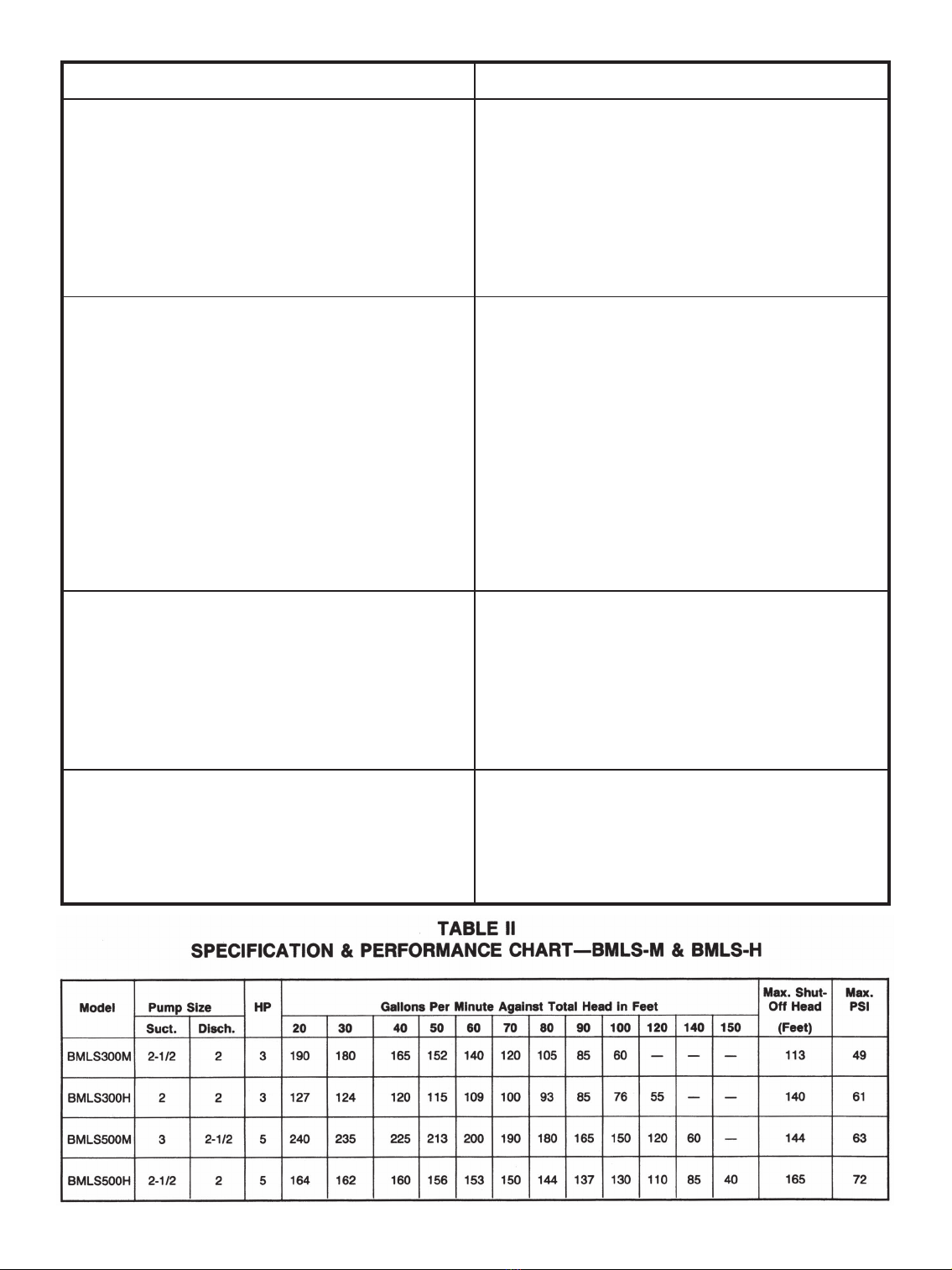
BMLS-M & BMLS-H
INSTALLATION, OPERATION & MAINTENANCE
INSTRUCTIONS
HP Phase Medium Head High Head
3 1 BMLS 300 M BMLS 300 H
3 3 BMLS 300 M3 BMLS 300 H3
5 1 BMLS 500 M BMLS 500 H
5 3 BMLS 500 M3 BMLS 500 H3
GENERAL INSTRUCTIONS
Examine unit for any visible shipping damage. Immediately
report any damage to the carrier. Check all accessory parts
carefully against the invoice. All pipe used should be clean
and free from rust and scale. Use pipe joint compound on
all joints to avoid leaks.
INSTALLATION & OPERATION
Pump Location: Locate the pump as near the well or water
source as possible, using short, direct suction pipe. Keep
the static suction lift (vertical distance between the center
line of the pump and water level) to a minimum. Mount the
pump on a solid, level foundation, which provides a rigid
and vibration free support. It should be located where the
unit is readily accessible for service and maintenance. The
pump should be protected against flooding and excessive
moisture.
Piping: Both suction and discharge piping should be
independently supported at a point near the pump to avoid
strains being placed on the pump. Start all piping at pump to
avoid strains left by a gap at last connection. It is advisable
to increase the size of both suction and discharge piping at
the pump if any appreciable run of pipe is required. Never
use a smaller suction pipe than the suction connection on
the pump.

Page 2
*
Suction Piping: The suction pipe must be kept free from
air leaks. The suction pipe must have a gradual slope upward
to the pump. Avoid any fittings which may cause an air trap.
A check valve is a built-in feature and no foot valve is
required.
Discharge Piping: A gate valve and union should be
installed in the discharge line. For removal of the pump for
service, close the gate valve, and disconnect at the union.
Priming the Pump: A tee installed in the discharge opening
of the pump and provided with a priming plug at the top
position; will enable you to fill the pump with water. Once
filled and the priming plug replaced, the pump will prime.
The priming time depends upon the vertical and horizontal
distance between the pump and the water level. The pump
should prime itself time after time as long as the built-in
check valve functions.
CAUTION: DO NOT run the pump before filling the pump
case with liquid, as it may damage the seal.
Storage of Pump: Drain liquid from pump to prevent
freezing. It is recommended that a good rust inhibitor be
put in the liquid and to prevent excessive corrosion. Be sure
motor is kept dry and covered.
When restoring the use of the pump, replace all plugs and
make sure all connections are tightly sealed. After a complete
check is made, make the initial prime according to directions
under the section, Priming the Pump.
ELECTRICAL
WIRING:
Check wiring and fuse charts before connecting wires to
service lines. Make sure the voltage and frequency of the
power supply agrees with what is stamped on the motor
nameplate. If in doubt, check with the power company.
Single Phase: Determine incoming voltage to motor. Where
possible, use 230V. Connect wiring to terminal board located
inside conduit box cover. Be sure voltage connections agree
with wiring diagram on motor nameplate.
Three Phase: Three phase motors require magnetic starters,
and can run in either direction, depending on how they are
connected to the power supply.
To Check for Proper Rotation: Remove the motor end
cover. This exposes the motor shaft. If hook-up is correct,
the shaft will rotate clockwise. If rotation is not clockwise,
reverse any two leads to the starter. The rotation will now be
correct.
GROUNDING THE MOTOR:
WIRING TO THIS PUMP MUST BE INSTALLED AND
MAINTAINED IN ACCORDANCE WITH THE
NATIONAL ELECTRICAL CODE OR YOUR LOCAL
ELECTRIC CODE. IF MORE INFORMATION IS
NEEDED, CALL YOUR LOCAL LICENSED
ELECTRICIAN OR YOUR POWER COMPANY.
Permanently ground the motor in accordance with the
National Electrical Code Article 250 or applicable local
codes and ordinances. It is recommended that a permanent
ground connection be made to the unit using a conductor of
appropriate size from a metal underground water pipe or a
grounded lead in the service panel. Do not ground to a gas
supply line. Do not connect to electric power supply until
unit is permanently grounded. Connect the ground wire to
the approved ground and then connect to the terminal
provided.
A metal underground water pipe or well casing at least 10 ft.
long makes the best ground electrode. If plastic pipe or
insulated fittings are used, run ground wire directly to the
metal well casing or use ground electrode furnished by the
power company.
There is only one proper ground connection on the motor. It
is located under the motor canopy and is painted green and
identified as GRD. Ground connection must be made to this
terminal. See wiring diagram on next page.
*

Page 3
4. Pry loose the ceramic seal by applying a screwdriver
between the seat and cavity in the adapter. Clean the
cavity from which seal was removed and the motor
shaft. (Figure 2)
INSTALLATION OF NEW SEAL:
1. Bolt adapter back on motor housing.
2. Clean polished surface of ceramic seat with a clean
cloth.
3. Wet the “O” ring in the ceramic seat with soap solution.
4. Press seat into cavity firmly and squarely with finger
pressure. If seat will not locate properly in this manner,
place cardboard washer over polished face of seat, and
use piece of standard pipe for pressing purposes.
(Figure 3)
5. Dispose of cardboard washer and again ascertain that
polished surface of seat is free of dirt or foreign
particles, and has not been scratched or damaged by
the insertion.
6. Inspect shaft to make sure that it is clean.
7. Clean face of rotating sealing washer with clean cloth.
8. Apply soap solution to inside diameter and outer face
of rubber drive ring.
9. Slide seal assembly on shaft (sealing face first) as far
as possible. This will insure a tight seal. Replace gasket
against shaft seal.
10. Slide impeller on shaft with key in position. Place
gasket, washer and gasket back in position on motor
shaft. Tighten impeller screw in shaft. (Figure 4)
11. Reassemble pump.
MAINTENANCE:
Be sure to drain pump during freezing weather to prevent
damage from frost. To drain, remove priming plug, or
suction trap cover, and drain plugs directly below the
suction inlet of the pump. Drain the suction pipe to a joint
below the frost line. All other pipes that may be exposed to
freezing temperatures should also be drained. Store the
pump as directed in the section under Storage of Pump.
WIRING DIAGRAM: 10-32 GROUND SCREW
(BINDING HEAD)
The motor grounding conductor need not be larger than the
circuit conductors supplying the motor providing circuit
conductors conform to the wiring data provided in this
manual.
PUMP SERVICE
This pump requires little or no service other than reasonable
care and periodic cleaning. The trap on suction trap models
should be reasonably clean at all times. After a reasonable
time of operation, the shaft seal may become worn and
require replacement. Follow the procedure as outlined in
this manual.
THE SHAFT SEAL:
The shaft seal consists of two parts, a rotating member and
a ceramic seat.
CAUTION: The highly polished and lapped faces of the
seal are easily damaged. Read instructions and handle the
seal with care.
REMOVAL OF OLD SEAL:
1. Remove 8 capscrews which hold the motor and adapter
to the pump body, and pull away as an assembly. Be
careful not to damage adapter gasket.
2. The impeller is keyed on the shaft. Remove impeller
screw, turn counter-clockwise, and slide impeller off of
shaft. NOTE: Be careful not to damage gaskets and
washer. It is not necessary to remove the key. Carefully
remove the rotating parts of the seal by prying up on
the sealing washer with two screwdrivers. (Figure 1)
3. Remove 4 capscrews which hold adapter to motor
housing and lay adapter on a clean surface.
Page 4
Failure to Pump
1. Pump not properly primed.
2. Speed too low.
3. Total head more than that for which pump was
intended.
4. Suction lift too great.
Reduced Capacity and/or Head
1. Air pockets or leaks in suction line.
2. Clogged impeller.
3. Strainer too small, or clogged.
4. Insufficient submergence of suction pipe.
5. Excessive suction lift.
6. Total head more than that for which pump was
intended.
7. Excessively worn impeller and wearing ring.
Pump Loses Prime
1. Air leaks in suction line.
2. Excessive suction lift and operating too near shut-
off point.
3. Water level drops while pumping, uncovering
suction piping.
Mechanical Troubles and Noise
1. Bent shaft and/or damaged bearings.
2. Suction and/or discharge piping not properly
supported and anchored.
1. Make sure pump casing and suction line are full of
water. See Priming Instructions.
2. Check voltage at motor terminals and at meter when
pump is operating. If low, refer to wiring instructions,
or check with your Power Company. Check loose
connections.
3. A pump designed for higher head is needed.
4. Locate pump closer to source of water. Make sure
suction piping is large enough.
1. Check suction piping.
2. Remove and clean.
3. Use larger strainer, or clean.
4. Add lengths of suction pipe to keep submerged and
well below the water surface.
5. If caused by suction pipe friction, enlarge piping.
Otherwise, move pump closer to water level.
6. A pump designed for higher head is needed.
7. Order replacement parts using Repair Parts List in this
manual.
1. Check suction piping.
2. Move pump nearer water level.
3. Check water supply. Add length of pipe to suction to
keep submerged and under water.
1. Take motor to authorized motor repair shop.
2. See that all piping is supported to relieve strain on
pump assembly.
TROUBLE AND CAUSE REMEDY

Page 5
Page 6
This manual suits for next models
9
Table of contents
Popular Water Pump manuals by other brands


Sykes AmeriPumps
Sykes AmeriPumps GP100M Operation and maintenance instructions

DUROMAX
DUROMAX XP WX Series user manual

BRINKMANN PUMPS
BRINKMANN PUMPS SBF550 operating instructions

Franklin Electric
Franklin Electric IPS Installation & operation manual

Xylem
Xylem e-1532 Series instruction manual

Milton Roy
Milton Roy PRIMEROYAL instruction manual