NPCatb M 02-01 User manual

GAS ANALYZER
TOXIC AND FUEL GASES
М02-01
Operating Manual
(Short version)

2
Contents
Page
1. Purpose 3
2. Technical specifications 4
3. Operation and description 5
4. Preparation for work 8
5. Operating procedure 10
6. Safety requirements 13

3
ATTENTION!
Read this instruction manual carefully before switching on the gas analyzer!
This manual explains how to use the gas analyzer toxic and fuel gases М 02-01,
consider of operating principles and technical characteristics for correct appliance
1 Purpose
1.1 Analyzer M 02-01 are designed for rapid automatic continuous measuring
methane concentrations, oxygen concentration, carbon monoxide concentration, carbon
dioxide concentration, the hydrogen sulfide concentration in the atmosphere for general-
purpose object class V-1a, and in underground mines, including dangerous by gas or dust
and sudden outburst (blast).
1.2 Type of gas analyzer - portable, automatic, multi-channel, for individual use.
1.3 Operating conditions of gas analyzers:
- the range of ambient temperature from –30 to + 40 °C, briefly in the ranges from
30-40 °C below zero and 40-50 ° C above zero;
- relative humidity up to 100 % at + 35 °C;
- the range of atmospheric pressure from 87.8 to 119.7 kPa (from 660 to 900 mm
Hg); - the speed of the gas air flow to 8 m/s;
- vibration with frequency (5-35) Hz and amplitude not more than 0.35 mm.
1.4 Gas analyzers provide:
- continuous measurement and digital indication of the monitored component;
- indication and signaling (sound and light intermittent signals) of exceeding the
established threshold values for the concentration of methane (or methane-hydrogen
mixture), carbon monoxide, carbon dioxide, hydrogen sulfide, oxygen;
- continuous automatic recording of information about the concentration of the
measured component and the parameters of the gas analyzer operation in real time in the
archival memory (the function of the "black box");
- fixation of the results of measurements of the concentration of the monitored
component at the command of the operator (immediately or with a delay), storing them in
the memory of the gas analyzer;
- sampling and indication of the fixed values from the gas analyzer memory;
- transmission of information stored in the "black box" mode or separately by the
operator's command, via the infrared port to the personal computer;
- indication of the current date and time;
- indication of the ambient temperature;
- indication of atmospheric pressure;
- fault indication;
- charge management, indication and signaling about the discharge of the battery;

4
- signaling about the «ON» position;
- information exchange with mine positioning systems when installing the
appropriate module in the gas analyzer.
1.5 Method of sampling - diffusion. Can be equipped with sampling devices.
1.6 In terms of resistance to climatic conditions, gas analyzers correspond to the
performance of NF category «2» (temperate and cold climate) in accordance with GOST
15150-69 for operation at temperatures from minus 30 to plus 40 ° C.
1.7 The body of the gas analyzer provides a degree of protection against access to
hazardous parts, from ingress of external solid objects and from penetration of water - IP66.
2 Technical specifications
2.1 Main measured parameters:
- methane volume fraction measurement ranges from 0 to 2.5 (5 to 100) %;
- range of indications of the volume fraction of methane from 0 to 100 %;
- measurement range of the volume fraction of oxygen from 0 to 25 %;
- measurement range of carbon monoxide volume fraction from 0 to 400 ppm;
- measurement range of the volume fraction of hydrogen sulfide from 0 to 100 ppm;
- measurement range of carbon dioxide volume fraction from 0 to 5 %;
- range of indications of the volume fraction of carbon dioxide from 0 to 100 %;
- range of ambient air temperature readings, from –50 to + 50 °C;
- range of atmospheric pressure readings, kPa from 15 to 115.
2.2 The sound pressure level developed by the acoustic radiator at a distance of 1 m is
not less than 75 dB.
2.3 Electrical power of gas analyzers is provided by the built-in power supply with a
nominal voltage of 3.7 V.
2.4 Operating time at least 25 minutes after a signal «battery discharge» at an ambient
temperature from –10 to + 40 °C.
2.5 Time of continuous operation of gas analyzers without recharging the power
supply unit with an alarm time of not more than 1 hour and backlight operation no more
than 30 minutes at ambient temperature:
- + (25 ± 5) °С, not less than 70 hours;
- –(28 ± 2) °С, not less than 10 hours.
2.6 Operating time without adjusting the reading is not less than 30 days.
2.7 Warm-up time not more than 90 seconds, including the time of automatic zero
setting when switched on.
2.8 Overall dimensions - not more than (132 x 67 x 25) mm.
2.9 Weight-not more than 0.19 kg.
2.10 In operation, the gas analyzer signals the on state - a short light and sound signal
every minute.
2.11 Тhe gas аnalyzer has two types of memory:

5
- archive memory, which are entered automatically with reference to the real-time
records, including: the results of measurements of the concentration of the controlled
components, temperature, pressure, the generalized fact of errors with the marking
"E1"..."E9", the fact of switching on the gas analyzer, the fact of discharge of the battery of
the power supply. Archive memory is read-only;
- memory of episodic measurements, in which, at the operator's command
(immediately or with a delay of 30 s, if necessary, the delay time can be increased or
decreased in the range from 0 to 99 s immediately before the measurement) are recorded at
the time of recording the readings, including: the value of the measured concentration of
methane (or combustible gases, or oxygen, or carbon monoxide, or hydrogen sulfide), the
value of the ambient temperature, the value of atmospheric pressure, the value of the current
time, generalized fact error appearance marked "E1" ... "E9", record number.
2.12 The volume of the archive memory allows you to memorize the records fixed
with a set time interval of 2 minutes for 60 hours with continuous operation of the gas
analyzer. After the specified time, the newly entered records are stored in memory, erasing
(overwrite) the first.
2.13 The amount of memory for episodic measurements is 4000 records. At filling of
the specified volume new records are brought in a place of the first. It is possible to clear
(format) the memory of occasional measurements in the tuning mode of the gas analyzer.
2.14 The operator can request from the memory of occasional measurements any
record with all the recorded values in the record displayed on the screen.
2.15 Records from the archive memory and the memory of occasional measurements
can be sending to a personal computer via an infrared port.
3. Operation and description
3.1. The action of the gas analyzer on the channel for measuring the volume fraction
of methane (or methane-hydrogen mixture) is based on measuring the signal of a
thermocatalysis sensor. The gas analyzer uses a scheme of periodic supply of voltage to the
sensor with a period of 7.5 sec. and an algorithm for auto-correction of readings.
When the volume fraction of methane exceeds 5.0%, the gas analyzer automatically
switches to the regime of thermal conductivity measurement of the volume fraction of
methane in the range up to 100%.
The action of the gas analyzer on the channel for measuring the volume fraction of
carbon dioxide is based on the thermal conductivity method.
The action of the gas analyzer on the channels for measuring the volume fraction of
oxygen, carbon monoxide and hydrogen sulphide is based on the electrochemical
measurement method.
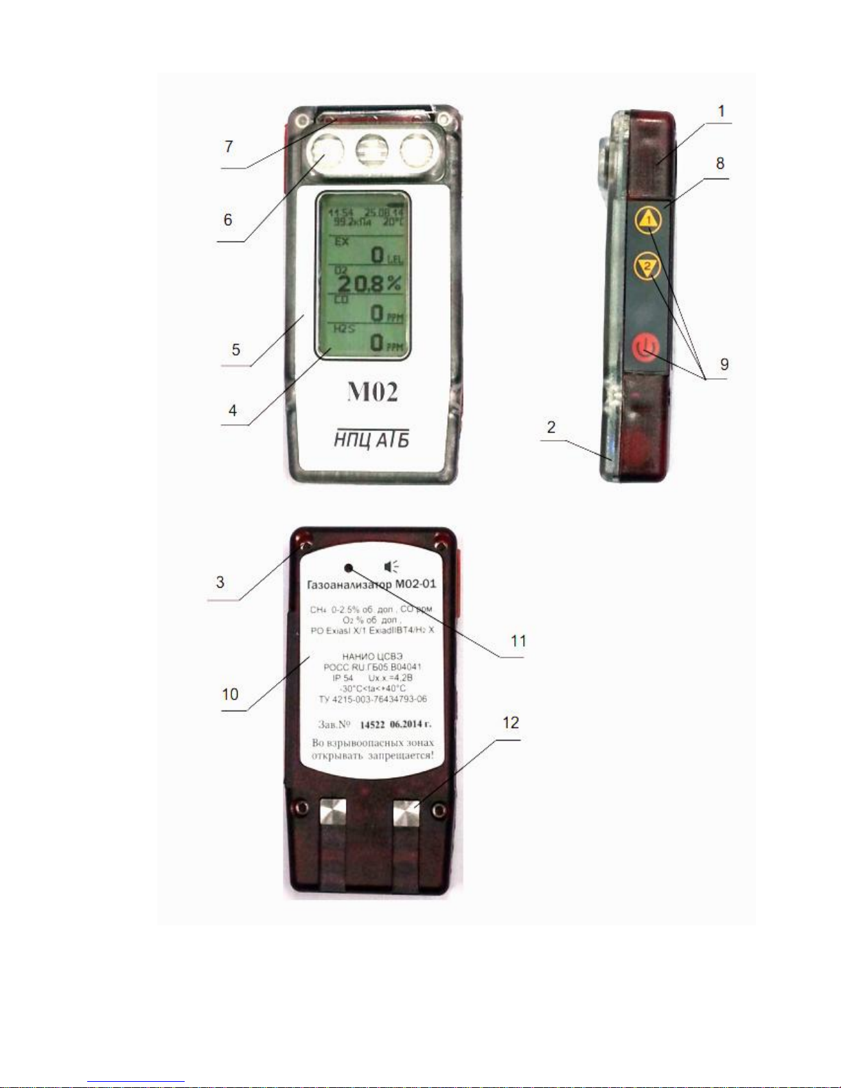
3.2 Appearance of the gas analyzer is shown in Figure 1.

6
Structurally, the gas analyzer is a protective shell of impact-resistant plastic,
consisting of a housing (1) and a cover (2), fixed to the body by four screws (3), one of
which is for sealing the gas analyzer with a special key. The cover has a rubber seal.
The housing has a measuring board and a power supply unit consisting of a Li-ion
battery and a protection board.
The power supply unit is located in the compartment of the lower part of the housing
and connect with the measuring unit by a two-wire cable with a connector.
At the request of the consumer, a radio module can be installed in the gas analyzer.
3.3 On the front surface, of the gas analyzer is located:
- display window (4);
- front shield (5);
- openings for supplying the gas mixture to the sensors (6), made in the form of a
grate consisting of inclined plates preventing direct moisture penetration onto the sensors.
A light-conducting zone (7) is located at the top of the cover to pass the signals of
four alarm LEDs, a battery charge LED, and signals from the infrared port.
3.4 There is a keyboard (8) with three buttons (9) on the side surface of the housing:
- scroll buttons - move through the menu items, change the digital value;
- execution buttons - switching on, switching off the gas analyzer, executing
commands.
WARNING! The commands are executed when the pressed button is release.
3.5 On the back of the case (1) there are:
- back shield (10);
- acoustic radiator window (11);
- self-cleaning contacts (12) for charging the battery of the power supply unit.
3.6 The gas analyzer does not have aggressive substances in its design and does not
require special disposal.

7
Figure 1.

8
4. Preparation for work
4.1 Checking the performance of the gas analyzer
4.1.1 In clean air, switch on the gas analyzer by pressing the button .
At the same time, a view window for M 02-01 with measuring channels CH4, O2, CO,
H2S
The lower area of the window displays the main menu:
« TURN OFF » - turn off the gas analyzer;
« SETUP » - go to setup mode;
“14.0 / BAEC” - 14.0 - software version, BAEC - checksum.
NOTE -the concept of "clean air" - atmospheric air in which there are obviously no
hydrocarbons.
4.1.2 Wait 5 seconds, ignoring the main menu suggestions.
The gas analyzer will pass to the testing phase (automatic zero or warm-up) and a
view window for M 02-01 with measurement channels CH4, O2, CO, H2S will appear on the
display.
The upper part of the window shows the current time, date, ambient temperature,
atmospheric pressure, battery icon and the degree of its charge (black field), as well
as the sign in the upper left corner in the case of installation in the gas analyzer radio
module.
The status line (immediately below the temperature) displays a message about the
action performed during the testing process.
In the lower field - the « TEST » indicator blinking during the test time and the
values of the set alarm thresholds (the first and second)
S M C АТB
O2 CO H 2 S
►T U R N O F F .
S E T U P
1 4 . 0 / В А Е С
М02
СH 4

9
4.1.3 Wait until the end testing process (no more than 90 seconds).
Upon its completion, the gas analyzer will go into the measurement mode and a view
window for M 02-01 will appear on the display in full configuration with a channel for
measuring hydrogen sulfide.
The gas analyzer readings from the channel for measuring the volume fraction of
methane should be set from «0.00%» to «0.05%», along the carbon monoxide measurement
channel from «0 ppm» to «2 ppm», through the hydrogen sulfide measurement channel
from «0 ppm» to «1 ppm », and the reading on the channel for measuring the volume
fraction of oxygen should be «20.8%» - «20.9%».
15:24 08.08.09
100.2 k P а24°С
A D J U S T M E N T
С Н 4 ТЕSТ
1 ▪ » 1 . 0 0 %
2 ▪ » 2 . 0 0 %
О2 ТЕSТ
1 ▪ » 2 0 . 0 %
2 ▪ » 1 8 . 0 %
СО ТЕSТ
1▪» 2 0 P P M
2▪» 8 5 P P M
Н 2 S Т Е SТ
1▪» 1 0 P P M
2▪» 2 0 P P M
15:24 08.08.09
100.2 k P а24°С
A D J U S T M E N T
D J U S T M E N T Н У Л Ь
С Н 4 Т Е SТ
1 ▪ » 1 . 0 0 %
2 ▪ » 2 . 0 0 %
О2 ТЕSТ
1 ▪ » 2 0 . 0 %
2 ▪ » 1 8 . 0 %
СО ТЕSТ
1▪ » 2 0 P P M
2▪ » 8 5 P P M
Н 2 S Т Е SТ
1▪ » 1 0 P P M
2▪ » 2 0 P P M
15:24 08.08.09
100.2 k P а24°С
СН4
0.00 %
О2
20.9 %
СО
0P P M
Н2S
0PPM

10
4.2 WARNING! When the operator performs actions that are not provided by the
logic of system the gas analyzer, a warning signal is given about the incorrect actions in the
form of a short intermittent light and sound signal.
5. Operating procedure
5.1 Gas analyzer operation in the measuring mode
To ensure the establishment of stable readings and a signal of an enabled state is 1
time per minute is fed a short light and sound signal. After that, you can start working with
the gas analyzer.
5.2 Alarm threshold concentration
When the threshold values of the concentration of the measured component are
reached, a light-sound intermittent signal appears, he display illumination turns on, and a
blinking icon of the reached first or second threshold level appears on the screen in the gas
code line, respectively, for M 02-01 with measurement channels CH4, O2, CO, H2S:
The alarm of the first threshold (light and screen backlight) can cancel by pressing
any of the buttons on the keyboard. At the same time, during the entire time of exceeding
the first threshold, the first threshold icon « 1▪» will display statically, as well as the current
value of the methane or oxygen concentration, respectively.
The alarm of the second threshold of each channel is not deactivated during the time
of exceeding the concentration of the set level.
15:24 08.08.09
100.2 k P а24°С
СН4
0.00 %
О2 1▪»
19.6 %
СО
0PPM
Н2S
0PPM
15:24 08.08.09
100.2 k P а24°С
СН4
0.00 %
О2 1▪»
19.6 %
СО 2▪ »
102PPM
Н2S
0PPM

11
5.3 Error alarm
When a malfunction appears on the screen in the process of operation, instead of the
concentration of the measured component, the symbol "E" (ERROR) "E1"..."E9" appears
on the screen than activated a continuous light and sound alarm, which lasts about 5
seconds.
In this case, it is necessary to turn off the gas analyzer and transfer to the technical
support service.
Do not use faulty gas analyzer.
5.4 Battery discharge alarm
When the battery of the power supply discharged below the permissible level,
warning signals about the discharge in the form of a light and sound signal (continuous
sound for (5 –6) seconds with the illumination of the display screen) and a flashing contour
of the battery icon on the display screen.
After the warning signals, the gas analyzer can work for another 25 minutes at a
positive ambient temperature or 1 minute at an ambient temperature below (–10 °C), and
then automatically turns off with a short-term light and sound signal at the time of
shutdown.
If you try to turn on the detector after it is disconnected due to the battery discharge
by the button, there will be an intermittent light signal during the hold button , but
the detector will not turn on. If necessary, you can try switching on again only after
charging the battery for at least 25 minutes.
5.5 Switching off the gas analyzer in the measurement mode
5.5.1 Press the button of the keyboard.
15:24 08.08.09
100.2 k P а24°С
СН4
E2.1
О2
20.9 %
СО
0PPM
Н2S
E3

12
A new active window with a set of working menu items appears on the display
5.5.2 Use any of the keyboard scroll buttons to move the active marker
"►" to "TURN OFF"
5.5.3 Press the enter button of the keyboard.
In this case, the window with the working menu will be replace by the deactivation
window
15:24 08.08.09
100.2 k P а
24°С
►E X I T
L I M I T S
D E V I C E S T A T U S
T U R N O F F .
15:24 08.08.09
100.2 k P а
24°С
E X I T
L I M I T S
D E V I C E S T A T U S
►T U R N O F F .

13
5.5.4 Use any of the scroll buttons the keyboard to move the active
marker to "YES" item, and press the button . The gas analyzer will turn off, as
indicated by a continuous light and sound signal and the subsequent disappearance of the
signal, the disappearance of information on the screen.
NOTE - The gas analyzer in the measuring mode can be switched off according to the
above diagram if it does not have a shutdown lock. In the event of an interlock, the gas
analyzer can be switched off automatically by installing it into the charger.
6 Safety requirements
6.1 When preparing and carrying out work with the gas analyzer, observe the
requirements of the regulatory documents on occupational safety applicable in the
industries where this gas analyzer is used.
6.2 WARNING! During operation, preserve the gas analyzer against shocks and
falls, as well as water and dirt entering the sensor and sound emitter hole
6.3 WARNING! The content of aggressive impurities (chlorine, sulfur, phosphorus,
arsenic, antimony, silicon and their compounds, poisoning the catalysis active elements of
the thermocatalysis sensor) in the controlled environment should not exceed the maximum
allowable concentration of the working area.
6.4 WARNING! Do not replace or charge the power supply unit in a hazardous area.
6.5 Do not use a gas analyzer with a damaged housing.
15:24 08.08.09
100.2 k P а
24°С
T U R N O F F .
►NO
Y E S
Table of contents
Popular Measuring Instrument manuals by other brands

Precision Digital Corporation
Precision Digital Corporation Trident PD765 quick start guide

PeakTech
PeakTech 2801 Operation manual

Schaller
Schaller FL2 user manual

Rohde & Schwarz
Rohde & Schwarz R&S CMW-KM5 Series user manual

RPB
RPB GX4 08-400 instruction manual

PCB Piezotronics
PCB Piezotronics IMI SENSORS ICP 624B21 Installation and operating manual

Axis
Axis ME-03 user manual

Associated Research
Associated Research HYPOTULTRA III 7620 quick start guide

Virginia Diodes
Virginia Diodes ZBD Operational manual

ABB
ABB EasyLine Series Instructions for Installation start-up and operation

Thermo Electron
Thermo Electron EPD MK2 Technical manual

Meatest
Meatest M921 user manual