NPZ TAL-100RS User manual

1
TAL REFRACTING
TELESCOPES
TAL-100RS
TAL-125R
INSTRUCTION MANUAL

2
NPZ Optics State Corp.
(Novosibirsk Instrument-making plant)
D. Kovalchuk 179/2 Novosibirsk,
630049 RUSSIAN FEDERATION
Fax +7 3832 261594
www.npzoptics.com

3
Page
General instructions. . . . . . . . . . . . . . . . . . . . . . . . . . . . . . 4
Technical specications . . . . . . . . . . . . . . . . . . . . . . . . . . 5
Inventory list . . . . . . . . . . . . . . . . . . . . . . . . . . . . . . . . . . . . 6
Construction of the telescope . . . . . . . . . . . . . . . . . . . . . .8
Preparing telescope for observations . . . . . . . . . . . . . . . .11
Assembling the telescope . . . . . . . . . . . . . . . . . . . . . . . . . . .11
Balancing the telescope . . . . . . . . . . . . . . . . . . . . . . . . . . . . 12
Aligningthenderscope............................13
Powersupplyandhandcontroller.....................14
Polar alignment . . . . . . . . . . . . . . . . . . . . . . . . . . . . . . . . . . . 15
Calibrating the setting circles . . . . . . . . . . . . . . . . . . . . . . . . 17
Observations . . . . . . . . . . . . . . . . . . . . . . . . . . . . . . . . . . . . 18
Visual observations . . . . . . . . . . . . . . . . . . . . . . . . . . . . . . . .18
Astrophotography . . . . . . . . . . . . . . . . . . . . . . . . . . . . . . . . . 19
Maintenance . . . . . . . . . . . . . . . . . . . . . . . . . . . . . . . . . . . . 20
Collimation (alignment) of the optics . . . . . . . . . . . . . . . . 21
Storage . . . . . . . . . . . . . . . . . . . . . . . . . . . . . . . . . . . . . . . . .22
Acceptance certicate . . . . . . . . . . . . . . . . . . . . . . . . . . . . 23
AppendixA:Brighteststarsvisible
in the Northern Hemisphere . . . . . . . . . . . . . . . 24
Due to continuous product improvements, specications are
subject to change without notice.
TABLE OF CONTENTS

GENERAL INSTRUCTIONS
Warning!
Never observe the Sun directly through your telescope or its
nder scope - permanent eye damage could result.
Do not let children hold observations through telescope without
adult’s control.
The telescope is designed for visual observations of celestial
objects and for astronomical photography. It requires careful
treatmentandsomeknowledgeofastronomy.Onlyinthiscase
theuseoftelescopewillbringsatisfactiontoitsowner.
Thetelescopemaybeusedatanambienttemperatureranging
from30°to-30°C.
When buying the telescope inspect the package to make sure
thatthe originalpackaging isin goodcondition, andseals are
notbrokenormissing.Havingopenedthepackage,checkthe
presenceofallcomponentsdescribedininventorylist.
Readinstructionmanualrstbeforeusingthetelescope.
4

Specication
Aperture, mm
Focal length, mm
Focal ratio
Telescope magnication, x
Resolving power
Limiting visual magnitude
Finderscope magnication, x
Finderscope aperture, mm
Focuser
Right ascension turning angle
Declination turning angle
Latitude adjustment range
Input voltage V AC
Frequency, Hz
Power, Watts
Output voltage, V
Dimensions, mm:
OTA* length
Telescope height
OTA weight, kg
Telescope weight, kg
125
1125
1:9
45; 180;
1"
12,0m
6
30
1,25";2"
360о
(24ч)
±90о
0...70о
220
50
5
12 DC
1250
1500
6,0
25
100
1000
1:10
40; 160;
1,3"
11,2m
6
30
1,25";2"
360о
(24ч)
±90о
0...70о
220
50
5
12 DC
1080
1450
4,3
23
TAL-100RS TAL-125R
*Optical Tube Assembly
TECHNICAL SPECIFICATIONS
5

6
INVENTORY LIST
Component
Telescope
Finderscope:
6Xx30
Polar axis nderscope 6xx23
Equatorial mount
MT-3S (MT-3S-2D):
with counterweight 2.2 kg
with counterweight 3.7 kg
Tripod:
wooden
metal
Power supply
Hand controller
Power cord (10 m)
Spare parts and accessories:
Plossleyepiecef’=6.3mm
Plossleyepiecef’=25mm
Reticle
T-adapterM42x0.75
Instruction manual
Optional accessories:
Pier:
C75(1000mm)
C110(800mm)
Plossleyepieces(1.25’’):
f’=7.5mm
f’=12.5mm
f’=17mm
f’=20mm
f’=32mm
f’=40mm
Superwideangleeyepieces(1.25’’):
f’=10mm(60°)
f’=15mm(65°)
f’=20mm(65°)
+
+
+
-
+
-
+
+
+
+
+
+
+
+
+
-
-
-
-
-
-
-
-
-
-
-
+
+
+
+
-
-
+
+
+
+
+
+
+
+
+
-
-
-
-
-
-
-
-
-
-
-
TAL-100RS TAL-125R
..
..
..

7
Ultrawideangleeyepieces(80°):
f’=15mm(1.25’’)
f’=20mm(2’’)
f’=24mm(2’’)
f’=25mm(2’’)
Directobservationlens:
PP-45°(1.25”)
PP-45°(2”)
2x Barlow lens
3x Barlow lens
Guideeyepieces12.5mm(1.25’’)
Off-axisguider(2’’)
ColorltersM28.5x0.6:
black
neutral
yellow
blue
red
green
ColorltersM48x0.75:
black
neutral
yellow
blue
red
green
Powercordextensioncablewithcaradapter
(10m)
-
-
-
-
-
-
-
-
-
-
-
-
-
-
-
-
-
-
-
-
-
-
-
-
-
-
-
-
-
-
-
-
-
-
-
-
-
-
-
-
-
-
-
-
-
-
Component TAL-100RS TAL-125R

8
CONSTRUCTION OF THE TELESCOPE
The telescope consists of three
mainparts:opticaltubeassembly
(OTA) (1), German equatorial
mount(2),apierortripod(3).
The optical tube is a basic component
ofthetelescope.Itincludesallmain
optical units such as a primary mirror,
acorrectorandaneyepieceunitwith
focusingmechanism.
A Refractor Telescope: parallel
beamofraysentersthetubeofthe
telescopeandisprojectedatthefocal
plane of the eyepiece (2) with the
helpofachromaticeyepiece(1).
Forcomfortobservationseyepiece
unitisinclinedon90°relativelyto
theopticalaxisofthetelescopewith
helpofatdiagonalmirror(3).
Astandardsetincludestwoeyepie-
cesandaBarlowlens,whichallow
observing celestial objects with
variousrateofmagnication.
The OTA supplied with a nder-
scope,makessearchingforceles-
tial objects easier.
Mirrors’ effective areas are cove-
red with high reection aluminum
coatings with protective level.

9
All lenses surfaces are covered
withantireectingcoating.
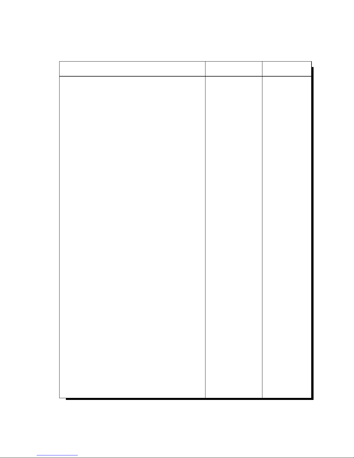
The eyepiece unit includes a
focuserwithaneyepiecetube.
Focuseroffrictionaltypeconsists
ofanaxiswithhandwheels(1)for
shiftinganeyepiecetube.
Smoothnessofaneyepiecemotion
isregulatedwithascrew(2).
Screw(3)xesaneyepiecetube
intheadjustedposition.
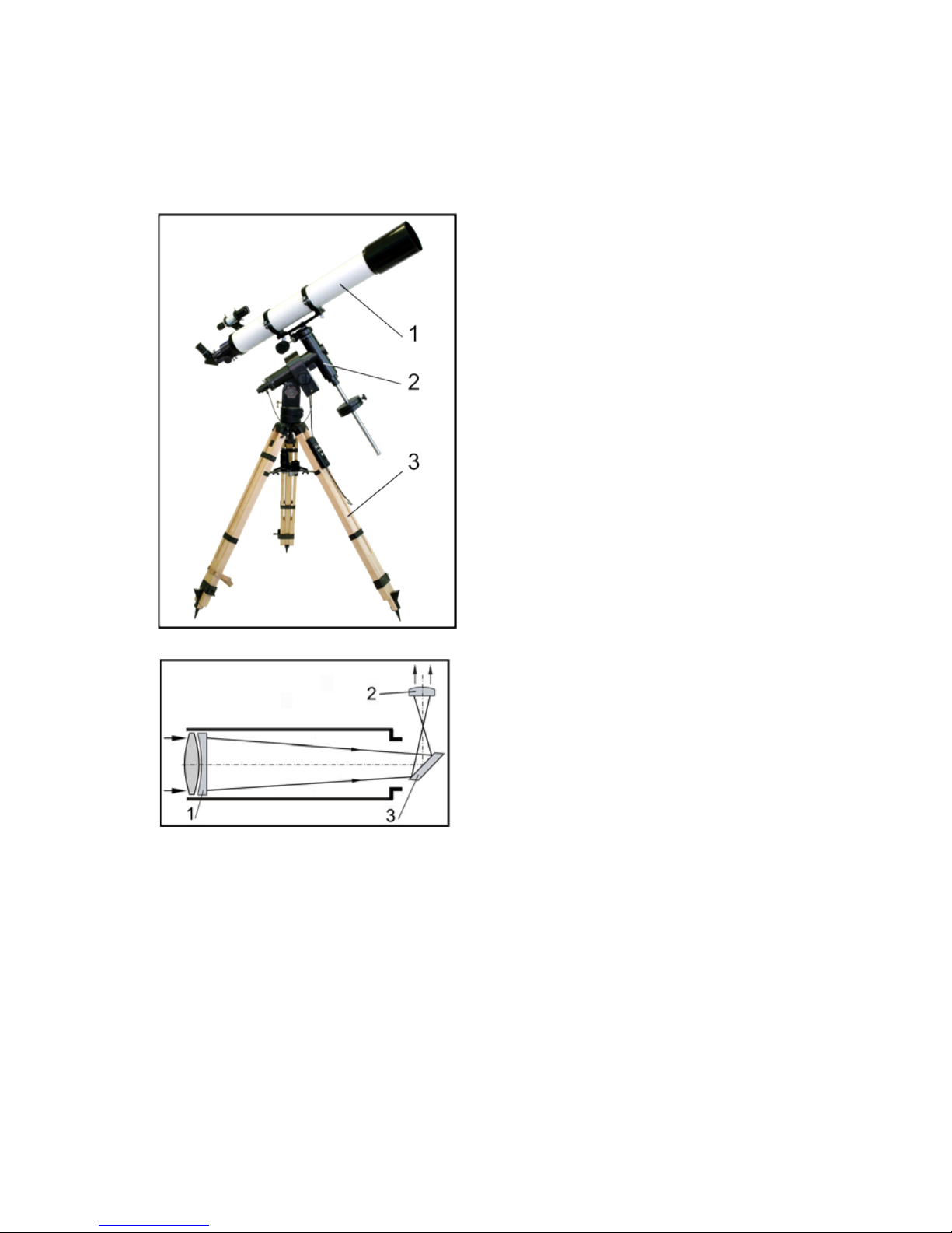
The equatorial mount is designed
for pointing the telescope at the
celestial objects and tracking their
movement.
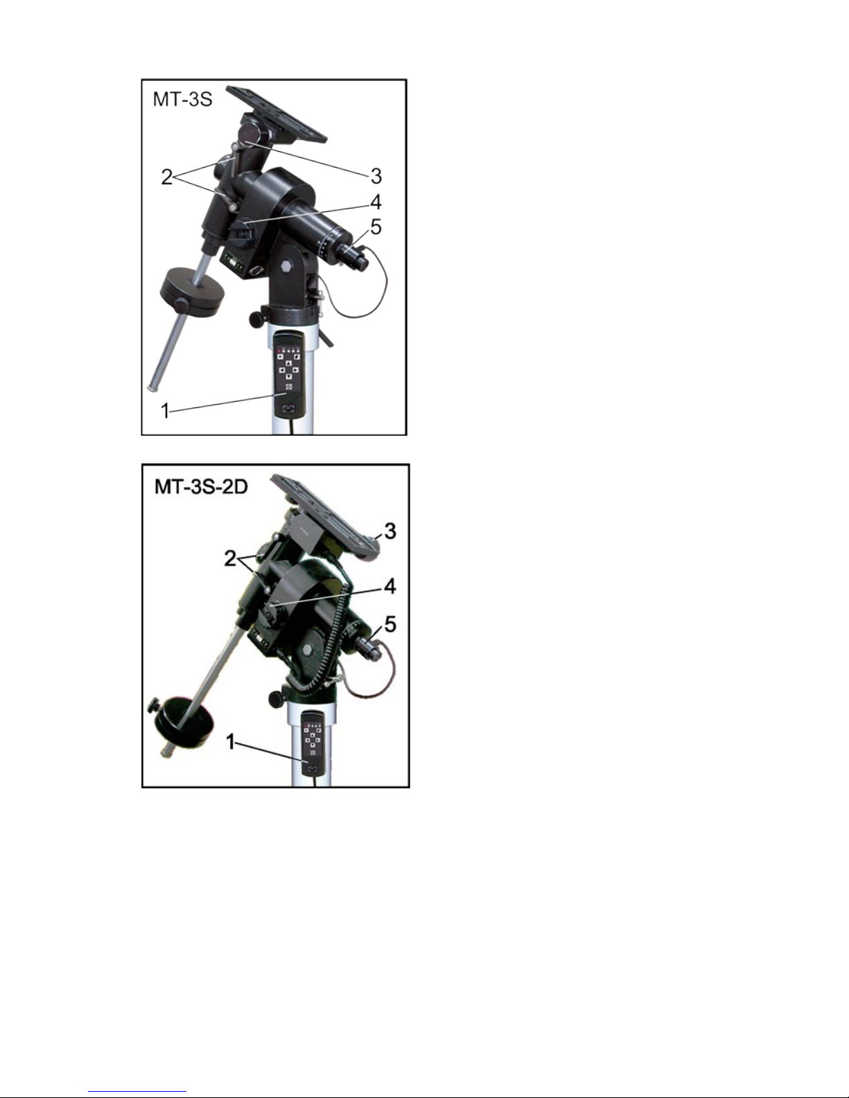
MT-3S mount consists of two
perpendicular axes: the polar axis
andtheaxisofdeclination.Thereisa
mounting plate with OTA rings on the
toppointofthedeclinationaxis,and
a counterweight shaft with counter-
weightsontheotherside.
The mount head has a clock drive
embedded, which enables tracking
ofcelestialobjectswithuserdened
speed.
Thespeedissetbyahandcontroller
and has three tracking rates: solar,
lunarandstellar,aswellastwoadditi-
onalcorrectionspeeds-acceleration
anddecelerationat50%.Handcon-
troller has a night light lamp.

10
Fortherstsight-inontheobject,
loosen the telescope’s Dec. and
R.A.locks(1)andmovetheteles-
copetocenteranobjectintheeld
ofview.
The fine alignment is done by
manual Dec. slow-motion controls
(2) on Dec. axis, and R.A. slow-
motioncontrols(3)embeddedinto
theclockdrive.
Thepolaraxishasembeddedpolar
axisnderscope(optional)(4)and
isxedinatripod(pier)mounting
headwithalatitudedial.
The pier servesforholdinganequa-
torialmountwithanOTA.Itconsistsof
thetubeandthreeattachablelegs.
The tripod canbebetterused ona
ruggedterrain.

11
ASSEMBLING THE TELESCOPE
Takeatripodoutofthepackage.
Place the pier on a firm plain
surface. Regulate the needed
height with help of pullout legs,
whicharexedbyknobs(1).The
pin (2) should be oriented to the
North.Thetripodisequippedwith
anaccessoryshelf(3)forcomfort
observation.
Taketheequatorialmountoutofthe
packageandplaceitonthetopof
thetripod.
Checkthepin(1)tobebetweentwo
azimuthadjustmentknobs(2).
Fixthemountonthetripodtightly
with help of knob (3). Make sure
thereisnowobblingofthemount
onthetripod.
Threadthecounterweightshaft(2)
intothebaseoftheDeclinationaxis
(6)oftheequatorialmountandx
it with the lock-nut (5). Unscrew
the safety washer/knob (1) and
slidethe counterweight(3) tothe
midpointonthecounterweightshaft
andsecureitinplacewiththelock
knob(4).Screwbackinthesafety
washer/knob(1).
Fix the tube rings (7) on the
mounting and lay out the OTA in
the rings.
PREPARING TELESCOPE FOR
OBSERVATIONS

12
Place the nderscope bracket (1)
inthewedgeslides.Fixthender-
scopewithsixthumbscrews(2).
Place the polar axis in the horizontal
position(0°onthelatitudedial),usingthe
widthadjustmentmechanism(1)withthe
loosenslow-motioncontrol(2).
Enable unrestricted motion of the
polar axis, turning the handle (1)
counter clock-wise.
Slide the counterweights along
the counterweight shaft until they
counterbalance the OTA.
Fix the polar axis.
Nowenableunrestrictedmotionof
theDec.axis,turningthehandle(2)
counter clock-wise.
FixthetubeandtheDec.axis.
Repeat balancing each time when
placing additional accessories on
the telescopic tube, such as photo
and video cameras, eyepieces,
guidesandotherdevices,whichen-
largetheweightoftheOTA.Keep
inmindthatifthetelescopeisnot
balancedproperly,theclockdrive
periodicerrorwillincrease.
BALANCING THE TELESCOPE
Toprovideasmoothmotionofthetelescopeandreliableoperationof
equatorialmountdrives,thebalancingofthetelescopesisrequired.

13
Place the crosshair (2) into the
eyepiece f’=25mm (1) and then
inserttheeyepieceinthefocuser
tube(3).
Point the telescope at the distant
object (at least 400 meters/yards
away), and then center it in the
telescopic eld of view using the
reticle. Fix telescope in this position
withtheR.A.andDec.locks.
Now, looking through the finder
scopeandusingthesixalignment
thumbscrews, center the object on
theintersectionofthecrosshairsof
the nder scope. In future, check
the coalignment of the telescope
andthenderscopepriortoobser-
vations.
ALIGNING THE FINDER SCOPE
Highmagnicationofthemaintelescopemakesitdifculttonda
requiredcelestialobjectintheskybecauseofthesmalleldofview.
Thisiswhythetelescopeisequippedwithalow-powernderscope
withawideeldofview.Thenderscopemakesiteasiertolocate
theobjectyouwantandthentoobserveitintheeldofviewofthe
telescope.However,fortheproperuseofthenderscope,itmust
bealignedwiththemaintelescope,sothatboththenderscopeand
the telescope point at the same position in the sky.

14
Place the switch of the power
supplyinthe“0”position.
Connect the power supply 12V
output with the mount socket using
thepowercord.
Plug in the power supply into the
220/110 V AC power outlet.
Placetheswitchofthepowersupply
inthe“l”position.TheLEDlighton
thepowersupplyshouldturnon.
Connecthandcontrollertothemount
withthespecialcutoffpoint(1).
Pressoneofthespeedbuttons(1)
to start the clock drive. The LED
lightonthehandcontrollershould
turnon(2).Pushthesamebutton
againtostoptheclockdrive.
Press one of the two speed
correction buttons (3) while clock
driveisworking,ifnecessary.The
LED light on the hand controller
should blink (2) while button is
presseddown.
POWER SUPPLY AND HAND CONTROLLER
Warning!
Always connect power supply to the mount using the power cord
with power supply disconnected from the power outlet.
Use only original manufacturer’s power supply fuse or analogue
(consult your dealer).
Always disconnect all the power, if replacing the power supply
fuse.

15
If the telescope is used in the
Southernhemisphere,thedirection
oftheclockdriverotationmustbe
changed.
Thisisdonewithhelpofswitcher
insidethehandcontroller.
Open the hand controller cover
and place the inside switch with
«N/S» (North/South) markings in
therequiredposition.
Releasethelatitudelock(1).Using
latitudeadjustmentknob(2),move
R.A.axisupordowninordertoset
the latitude of your location (see
latitudedial).
Re-tightenthelatitudelock(1).
POLAR ALIGNMENT
DuetotheEarth’srotation,celestialobjectsmoveinthetelescope
eldofview(thehighertelescopemagnication-thefasterthose
movementsappear).
Polaralignmentofthetelescopeallowsmorecomfortableobservations,
becauseyoucanfollowobjectsbymovingthetelescopeaboutone
axis,thepolaraxis(orRightAscension(R.A.)axis),whichisinparallel
withtheEarth’saxis.

16
For visual observations point the
R.A.(polar)axisofthetelescope
towardsPolaris(αUMi).Seethe
picture.
With this level of pointing
accuracy, very little use of the
Dec. slow-motion control is nece-
ssary for celestial objects tra-
cking.Lesscorrectionisrequired,
when polar alignment is done
more precisely.
More precise polar alignment is
requiredforastrophotography.
MT-3S mount equipped with
a polar axis finder scope (1),
for precise polar alignment,
with a reticle illumination. The
reticle also has major stars of
the Ursa Minor constellation,
includingPolaris,depictedforthe
Northernhemi-sphere,andstars
oftheOctansconstellationforthe
southern hemisphere.
Match stars depicted on the
reticle with the celestial objects
inthesky,usingazimuth(2)and
latitude (3) adjustment knobs
androtatingthepolaraxisnder
scopearounditsaxis.
Ursa Major
Axisofdec-
linations
Polar axis
Polaris

17
Level the Dec. axis (put it in the
horizontalposition)andbyrotating
R.A. setting circle put it in a «0»
(zero)position(seepicture).
For the Dec. setting circle calibration
ndabrightstarfromthestaratlas,
and bring selected object to the
centerofthetelescopiceldofview.
RotatingDec.settingcircle(1),set
theDeclinationofthestarobserved.
Correct Dec. setting circle calibra-
tion by selecting next star.
CALIBRATING THE SETTING CIRCLES
R.A.andDec.axeshavesettingcircles,whichenableobserverto
locateanobjectintheskybyitscelestialcoordinates–rightascension
(R.A.)andDeclination(Dec.).
Calibration of setting circles is done after polar alignment of the
telescope.

18
OBSERVATIONS
Point the telescope at any chosen
object, and do some coarse
adjustments to put it in the nder
scopeeldofview.Thencenterthe
object using slow motion controls
–rstinthenderscopeandthen
in the main telescope field of
view, when observing through the
eyepiece.
Use focus knobs to focus, when
changing eyepieces.
Provided eyepieces give several
magnification options for an
observer.
VISUAL OBSERVATIONS
Whenusinghighermagnicationnotonlythevisibleimagesizeappears
largerinthetelescope,butalsoblurringanddistortionoftheimage,
startwinkle,causedbyatmospherebecomemoresignicant.
Pleasenotethatsomenightscouldhavebadobservationconditions
becauseoftheatmosphericturbulence.EvenobservingneMoon
surfacedetailscanbedifcult.
Avoidobservationsthroughawindow,becauseofthewindowglass
aberrations,andtemperaturedifferencesbetweeninsideandoutside
air,whichwillcauseimagestolookblurredanddistorted.
Putasoftcoveronthetelescopeanditspowersupplyafterobserva-
tions,ortoprotectitfromrain/snow.
TAL-100RS
Plosslf'=25mm Plosslf'=6.3mm
40x160x
TAL-125R
Plosslf'=25mm Plosslf'=6.3mm
45x180x
..
..
..
..

19
To mount the camera on the teles-
cope, take the mirror (1) and a
camera adapter (2) away and
unscrew the camera objective.
Screwthecameraadapterintothe
focuserdrawtube.
AttachtheT-ring(T-adapter)tothe
cameraandthreaditontotheca-
meraadapter.
Preciseguidingcanbedonewithan
off-axisguideroraguide-telescope
(soldseparately).
Use slow motion controls and
buttonsofhandcontrollertoavoid
shiftingofthestarfromthereticle.
To minimize such adjustments
andforbetterphotographyquality
more precise polar alignment is
required.
ASTROPHOTOGRAPHY
Astrophotography is executed with compact reex camera with
objectivethread M42x1(M42x0.75 threadcamera adapteris also
suppliedwiththetelescope).

20
Inordertokeeptelescopeingoodoperatingconditiononeshould
providegoodcareandmaintenancefortheinstrument.Pleasenote
that lens or mirror surfaces should be cleaned as infrequently as
possible, only when absolutely necessary.
Optics self-cleaning only permitted after expiration of manufac-
turer limited warranty!
Keeptelescopecleanandprotectitfromanyphysicaldamage.
Useaclean,softclothtoremovedustfromallmetallicsurfaces.
Thenwipethemwithaclothwettedinacid-freevaselineanddry
with a napkin.
Wipetheobjectiveandeyepiecelensesbydrylinennapkin.Grease
spotsremovebycottoncloth,wettedwiththepurespirit(alcohol).
Usethecottoncloth,wettedwiththepurespirit(alcohol),without
pressuretocleanthesecondarymirrorsurface,havingremoveddust
fromtheirsurfacesbysoftbrushrsttoavoidsmallscratches.
Keepthedustcoveronthefrontofthetelescopeandtheendcap
onthefocusertubewhennotinuse.
MAINTENANCE
This manual suits for next models
1
Table of contents
Other NPZ Telescope manuals