NPZ TAL-150K User manual

1
TELESCOPE TAË-150K
Service manual

2
CONTENTS
Page
1. General directions 3
2. Specifications 4
3. Standard equipment 5
4. Design and principle 8
5. Optical train 12
6. Preparation for operation 15
6.1. Telescope assembling 15
6.2. Telescope balancing 15
6.3. Precautionary measures 16
7. Order of operation 18
7.1. Operation with telescope 18
7.2. Photographic observations 19
7.3. Telescope and atmospheric conditions 19
8. Maintenance 20
9. Rules of storage 22
10. Acceptance certificate 22
Supplement. Table of close stellar pairs for testing
image quality of the telescope 23
The telescope is subject to continuous development and improvement,
consequently it may incorporate minor changes in detail from the information
contained herein.
11.01

3
1. GENERAL DIRECTIONS
ATTENTION!
Telescope TAË-150K (hereinafter in the text referred to as «telescope») is
not intended for direct visual observation of Sun at full operating aperture.
Because of high light intensity an image of Sun in focus of primary mirror has
a high temperature. To avoid on overheating of corrector it is recommended
to avoid any direct observation of Sun disk.
One should remember that overheated corrector being in field of direct
sunlight can be out of order or make a turbulent air torrents in telescope tube
that to reduce considerably a quality of image.
Also if it is necessary to leave a telescope out of door (for example, to dry it)
one should orient it so that the direct sunlight do not get into the optical system.
The telescope can operate normally at the ambient temperature from 30°C
to minus 30°C.
It is a precise powerful amateur astronomer telescope. It demands a careful
handling and certain knowledge in the field of astronomy. Only in this case
user will be fully satisfied.
When buying the telescope one should pay attention to the package safety
ensured by the seal of the manufacturing plant. After unsealing the case one
should check compliance of the complete set denoted in the list of enclosure.
Prior to using the telescope one gets acquainted with its handling and order of
operation.

4
2. SPECIFICATIONS
Diameter of objective lens (operating aperture), mm 150
Focal length, mm 1551
Relative aperture 1:10.3
Magnification and angle field of view (changeable):
- with the eyepiece f=25 mm 61x
41.5¢
- with the eyepiece f=10 mm 125x
20¢
- with the eyepiece f=25 mm and Barlow lens 158x
16¢
- with the eyepiece f=10 mm and Barlow lens 321x
8¢
Photographic angle field of view 40¢
(23.3mm)
Screening of pupil in center 13%
Resolution limit 0.8²
Pellucid capacity 13.4m
Range of slow-motion control on the axes within ±4°
Rotation of the telescope:
in right ascension (hour-long angle) 360° (24h)
in declination 360°
Operation limit by latitude 0°-70°
Angular field of view of the finderscope 8°
Magnification of the finderscope 6x
Voltage of the supplying mains, V 220(110V)±10%
Current frequency 50Hz (60Hz)
Output voltage of the supply unit, V 12
Size of the telescope, mm:
length tube 425
height 1130
Weight of the telescope, Kg 23

5
3. STANDARD EQUIPMENT
Name Qty
Telescope 1
Supply unit 1
Eyepiece of f=25mm 1
Finderscope 1
Equatorial mounting 1
Supports 3*
Tripod 1*
Pier 1*
Car mains bundled conductors 1
Control console 1
Accessories and Parts
Eyepiece of f=10 mm 1
Barlow lens 1
Reticle 1
Black light filter (solar) 1
Neutral light filter (gray, lunar) 1
Blind 1
Bushing 1
Adapter 1
Stopper 1
Screwdriver 1
Napkin 1
Fuse link ÂÏT19-0.16À (220V) 1
Fuse link ÂÏT19-0.32A (110V) 1
Brush N 6 1
Housing 1
Service manual 1
* Telescope can be completed with a metal pier or tripod

6
Fig.1. General view:
1 telescope tube; 2 equatorial mounting; 3 control console; 4 cable
assembly; 5 supply unit; 6 support; 7 pier; 8 eyepiece unit; 9 finderscope
4
3
2
1
8
9
7
65

7
Fig. 2. General view with tripod :
1,3 - stoppers; 2 - table
3
1
2

8
4. DESIGN AND PRINCIPLE
The telescope (fig.1, 2) consists of three basic units such as the telescope
tube, equatorial mounting, pier with supports or tripod and supply unit.
The tube 1 (fig.1) is the basic part of the telescope, which embodies the
optical units such as a primary mirror, corrector, eyepiece set and finderscope.
The primary mirror 1 (fig. 3) is fastened with the collet bushing 2 in the
center hole. The blending tube 3 on the collet bushing prevents stray light. The
Fig. 3. Assemble of primary mirror together with eyepiece set:
1 - mirror; 2 - bushing; 3 - blending tube; 4 - screws;
5 - bushing; 6 - focusing mechanism; 7 - diagonal mirror; 8 - eyepiece;
9 - screw; 10 - back flange; 11 - screw
1
23
11
10 8
9
7
65
4

9
mirror is adjustable on ball hinge by means of the six screws 4.
The corrector (fig.4) consists of secondary mirror 2 and meniscus lens 3
spaced by means of padding rings 4 in the mounting 1. The corrector is
6
7
2
13
4
5
Fig. 4. Corrector:
1 - mounting; 2 - reflecting lens; 3 - meniscus; 4 - padding ring;
5 - hinge bushing; 6 - hinge ped; 7 - adjusting bolt-screw; 8 - cap
8

10
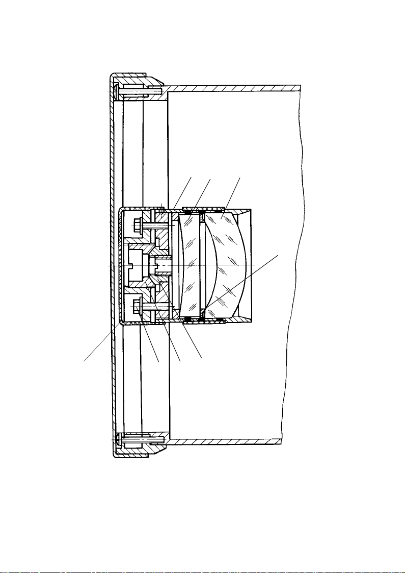
adjustable on the ball hinge 5,6 by means of adjusting screws 7. The
corrector assembly is mounted in the telescope tube.
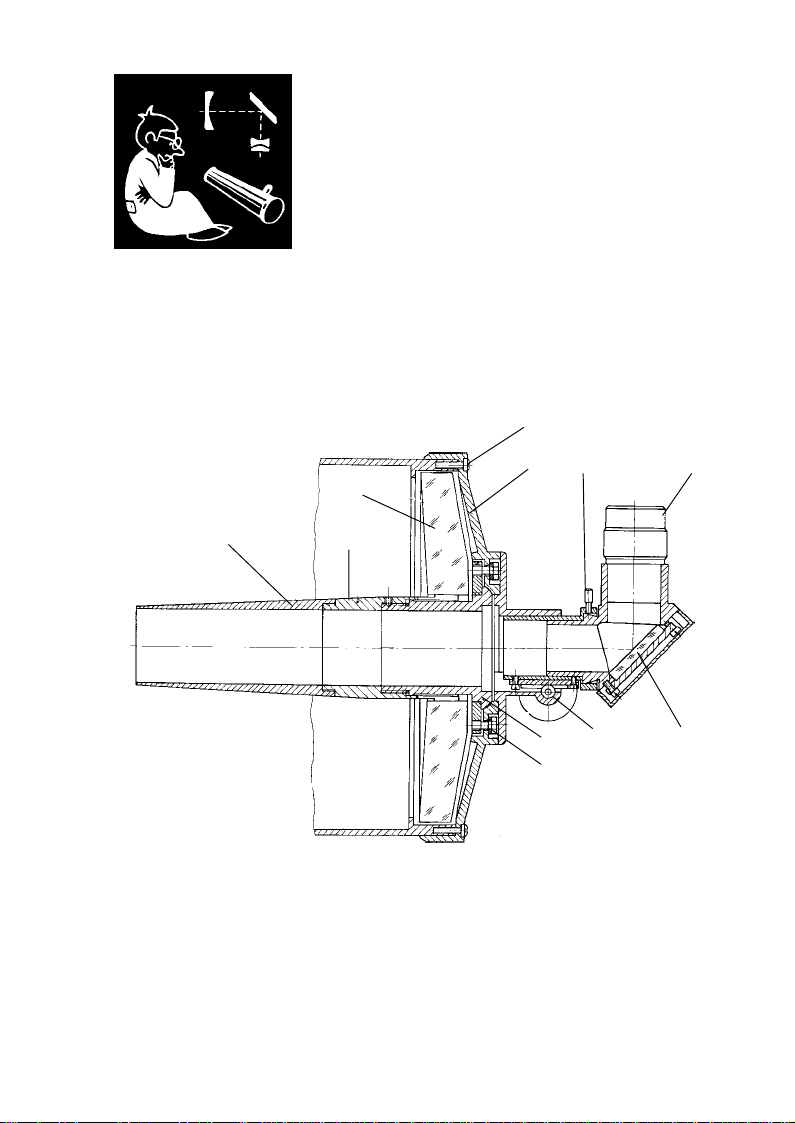
Eyepiece set (fig.3) consists of focussing mechanism, diagonal mirror, set of
symmetrical eyepieces f'=25mm and f'=10mm fixed in the mounting of 31.8mm
(1.25), Barlow lens mounted in the same one.
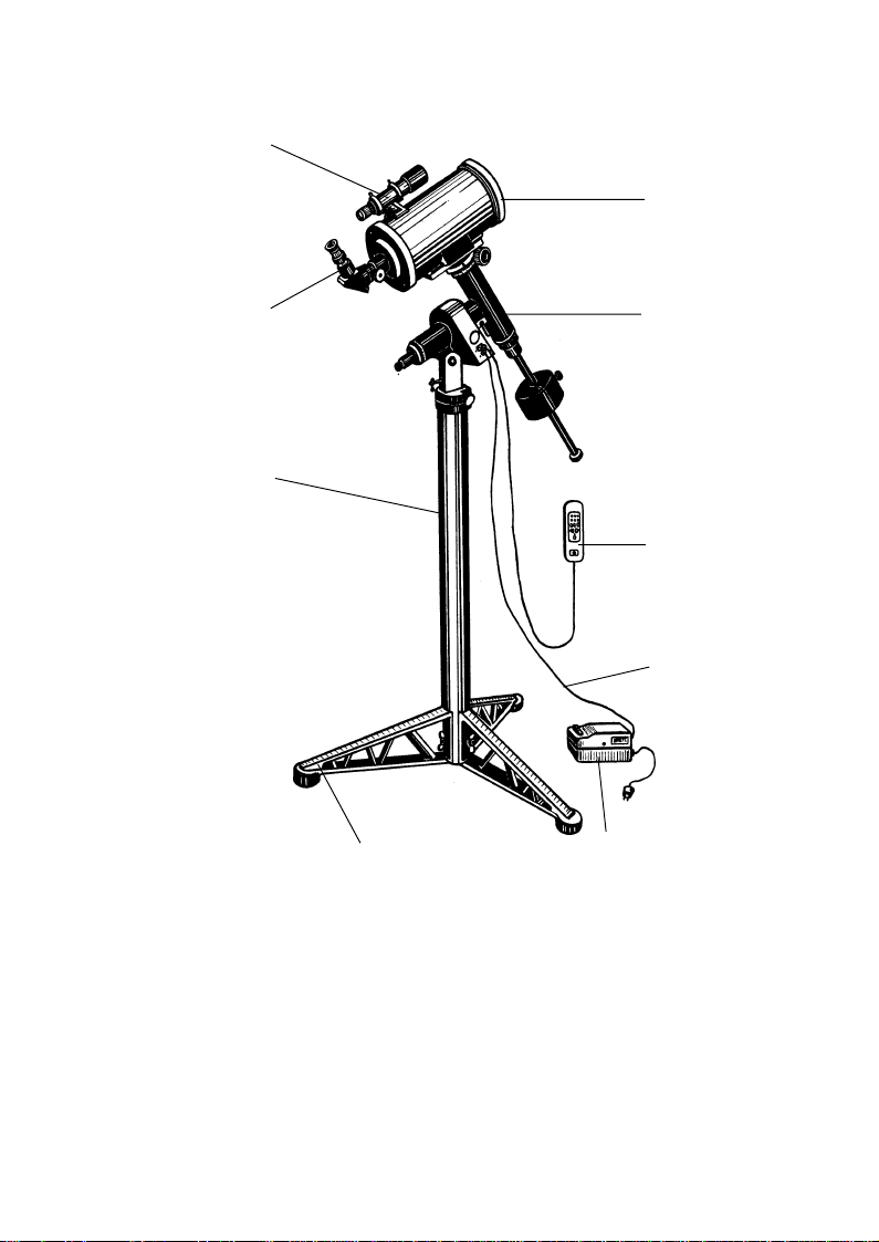
Finderscope 6 (fig.1) is a telescope with 8x magnification and view field 7°.
The equatorial mounting (fig.5) comprises the polar axis unit 5 and
declination axis unit 9 that are perpendicular each other. The declination axis
unit is provided with the bracket 7 for telescope tube on the one side and with
the movable counterweight 10 on the other side to adjust the telescope balance.
The pole finder 3 inside the polar axis unit is provided to align the mounting
with the polar axis. The polar axis unit is attached to the bracket 1 provided
with the latitude scale. The alignment to polar axis is ensured by means of
elevation gear 2 and direction gear 12.
The mounting is provided with the watch drive inside for automatic tracking
a celestial object at specified speed.
Each of axis units is provided with the setting circle 4, 8 to define the right
ascension and declination angles of an object viewed.
The buttons 2 of the control console (fig.7) select three tracking rate: they
are the celestial, solar and lunar speeds; and the buttons 3 can switch on two
adjustment mode which speed up or slow down the tracking with factor 2.
The control console is connected to the mounting by means of plug 5. The
control console is provided with the local lighting activated by the button 4.
Pier 3 (Fig. 1) consists of a pipe with three supports 4.
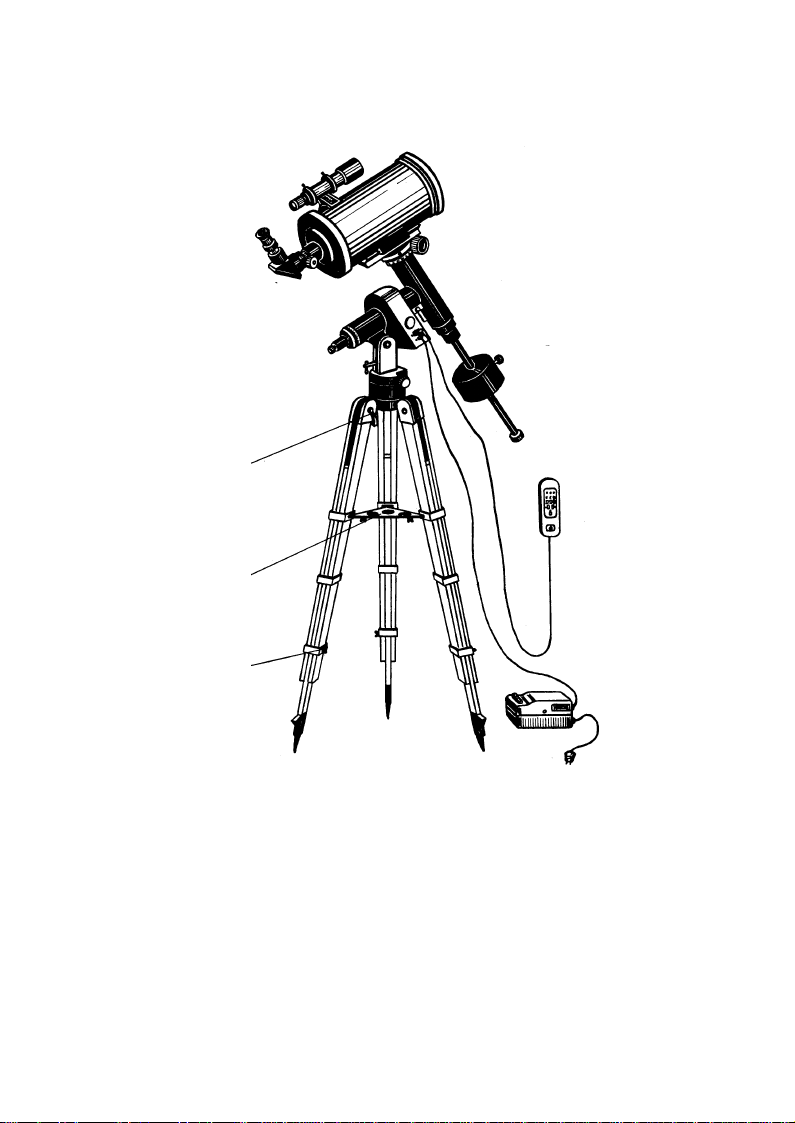
The tripod (Fig. 2) allows to adjust a height of telescope and to fix each leg
of tripod with the help of stops 1 and 2. It is completed with table 3.
Supply unit 7 (a step-down transformer) is designed for converting of voltage
supply mains 220V, 50 Hz (or 110V, 60Hz) in to the voltage supply 12V which
is necessary to supply a safe operation of telescope.

11
Fig. 5. Equatorial mounting:
1 bracket with scale; 2 elevation gear; 3 pole finder; 4 - right
ascension scale; 5 polar axis unit; 6 fine-motion handwheel; 7 bracket;
8 declination scale; 9 declination axis unit; 10 counterweigh; 11 lock
handle; 12 direction gear
8
9
10
11
1
2
3
4
5
6
7
12

12
5. OPTICAL TRAIN
Telescope TAL-150K is developed on the basis of Klevzovs original optical
train, which does not use any aspherical surfaces. Klevzovs optical train (fig.6)
consists of primary concave mirror 1 and correcting unit consisting of two single
lenses 2,3. The lens 2 is made in form of negative meniscus directed by concave
side to the observed object. The lens 3 is negative one having a reflecting
surface.
Reflecting from the primary mirror 1 a beam passes through correcting lenses
2,3, reflects from the reflecting surface of lens 3, passes through correcting lens
forming an image of observed object in the focal plane which is located behind
a primary mirror 1.
In the main the Klevzovs optical train is an improved Kassegran optical
train, which has a spherical primary mirror and double lens corrector having a
reflecting surface that to allow reducing an aberration. A meniscus 2 corrects a
spherical aberration and coma and fully compensates a little longitudional
chromatic aberration with the help of negative lens 3. Because two lenses of
corrector are made of the same mark of glass a secondary color of system is
extremely little one, and correction of the residual aberration is perfect that to
Fig. 6. Optical train of telescope:
1 - primary mirror; 2 - eyepiece; 3 - diagonal mirror- lens;
4 - secondary mirror; 5 -meniscus; 6 - viewfinder
61
2
3
45

13
allow obtaining an image of observed object which can be compared with the
image of object obtained with the help of mirror telescope. Besides, Klevzovs
optical train is not subject to unadjastment.
The lacks of aspherical surfaces, high quality of correction of the residual
aberration in the wide range of spectrum and small length are indisputable
advantages of Klevzovs optical system. The telescope has a possibility to achieve
F - number to 8.7 that to allow satisfying all requirements of amateur astronomer.
Telescope is completed with two symmetrical eyepieces f'=25mm and
f' = 10 mm and 2xBarlow lens. For easy observation of celestial objects near by
zenith an eyepiece set of telescope is turned to optical axis of tube by 90° with
the help of diagonal mirror 4. To locate an object in the center of view field the
telescope is completed with finderscope, which consists of objective lens 8,
reticle with the cross 9 and eyepiece 10.

14
1
2
3
4
5
Fig. 7. Control console:
1 indicator; 2 speed selection buttons; 3 tracking correction buttons;
4 local lighting switch; 5 plug

15
6. PREPARATION FOR OPERATION
6.1. Telescope assembling
Prior to assembling the units and parts should be cleaned from the sluicing
compound of the plant.
The telescope is assembled in the following way.
Three supports provided with captive screws are fixed to the lower end of
the pier through holes. The equatorial mounting is set on the upper end of the
pier. At the same way it is fixed on the tripod.
The polar axis is set by inclining the equatorial mounting by the scale to the
latitude of the observers site and fixed with a handle 2 (fig.5). The telescope
tube is mounted on the supports of the saddle and fixed by means of two clips
with the help of hinged screws.
The finderscope is mounted on the tube in two rings and fixed with six set
screws available on the rings.
In transportation and storage a hole in the eyepiece tube is plugged with a
stopper which should be removed and put in the case in preparation for
operation.
For obtaining the required magnification of the telescope the respective
eyepiece or the eyepiece with Barlow lens (Fig. 6) is inserted in the eyepiece
tube.
Set the power switch to position I. Connect the power source output 12 V to
the socket in mounting. Connect the power source to mains 220 V, 50 Hz (110 V,
60 Hz). The power indicator will light.
Connect the control console to the mounting and press one of the buttons 2.
If the indicator 1 lights the telescope is ready to operate. Repeated pressing of
the button will switch of the watch drive.
6.2. Telescope balancing
It is important to adjust the proper balance of movable parts on the equatorial
mounting.
In order to balance the telescope on declination axis, set the declination
axis horizontally, loosen the locking handwheel and move the tube along the
bracket until complete balance is reached. Lock the tube position again.
Set the polar axis horizontally, loosen the locking handle 11 and adjust the
position of the counterweight 10 to balance the telescope around polar axis.
In the case the telescope is provided with optional tools (e.g. photo camera)
the telescope should be balanced again.

16
6.3. Precautionary measures
The rate of the fuse link mounted in the supply unit must be in compliance
with the rate denoted under the fuse link holder.
Mount the fuse link only after complete disconnection of the supply unit
from the mains.
Connect the bundled conductors to the watch drive and supply unit when
the supply unit is disconnected from the mains.

17
Fig. 8. Tools and accessories:
1 cap; 2 eyepieces; 3 Barlow lens; 4 light filters; 5 screwdriver; 6 napkin; 7 blind;
8 reticule; 9 adapter; 10 bushing
5
4
3
2
1
67
8
9
10

18
7. ORDER OF OPERATION
7.1. Operation with telescope
Choose a site and prepare it for telescope installation. It should be even and
solid. Install the telescope on the site and check whether the telescope stand
stably.
Aim the polar axis at the pole and elevate it by the angle according to
geographic latitude of your observation site by means of elevation 2 and
direction 12 gears. Test the aiming with the pole finder. The reticule of the pole
finder is marked with the objects of the Ursa Minor (Dogs-tail constellation),
including the Pole Star (for northern hemisphere), and of the Octans constellation
(for southern hemisphere), facilitating the aiming to celestial pole.
If the telescope is reasonably well aligned with the polar axis, therefore,
very little tracking corrections are necessary during observation.
The handwheel 6 ensures the declination correction. The right ascension is
corrected by means of button 3 of the control console (Fig.7). All corrections
are applied to continuous operating drive.
Note if you travel from the Earths Southern Hemisphere to the Southern one
and vice versa you should change the direction of watch drive revolution. This
procedure is performed once by means of the dedicated switch inside the control
console. To do it open the control console and set the switch to appropriate
position.
The magnification of the telescope is large and consequently its field of
view is low. Therefore the telescope is provided with the viewfinder.
The optical axes of telescope and viewfinder must be aligned. Set the reticule
8 (fig.8) into the eyepiece 25 mm and then mount them into the focuser. Aim
the telescope at a remote object. Align the objects image with the crosshair by
means of six setting screws.
After aiming of polar axes the setting circles can be used to find a celestial
object by its coordinates.
The right ascension circle is to be set first. Set the declination axis 9 (fig.5) unit
horizontally exactly and turn the circle to 0 mark.
To set the declination circle, find out declinations of two or three bright
stars in the celestial objects tables and get the selected star into center of view
field at maximal magnification.
Then turn the declination circle to declination coordinate of the star.

19
7.2. Photographic observations
Photographing star fields is carried out with the use of the telescope in the
main focus. To make it one should use a small size 35-mm camera or other
devices having fitting thread of 42x1.0mm or 42x0.75mm. To mount a camera
it is necessary to remove eyepiece from tube and to mount a bushing with the
thread of 42x1.0mm. If it is necessary one should mount an adapter on the
bushing when using the telescope with camera provided with the thread
42x0.75.
Mounted a camera one should make a focus it and to balance the telescope.
The exposures, which are required for photographing the star fields, are
tenths of minutes without hindrance of the street lighting. Therefore, for this
period of time one should see to it that the camera follows the sky precisely in
its diurnal rotation. Near the center of the field of view of the camera one
chooses the bright star to which the telescope is pointed. To keep the star on
the reticle cross hairs of the finderscope is the problem for an observer for the
whole period of exposure. As the cross-hairs of the finderscope is not illuminated,
the image of the guide stair should be slightly defocused in order to cross a
light circle of the unsharp image of the star by the cross-hairs and to keep the
star in this position for the period of exposure.
One applies minor corrections for a clockwork drive keeping the star on the
cross hairs for the whole period of exposure. One corrects the position of the
guide star with the micrometer screw of the declination axis if necessary. To
obtain the minimum corrections in declination the polar axis should be set as
precisely as possible to the celestial pole. One should remember that if the
polar axis is set incorrectly, even in the case when the star image is kept on the
cross-hairs, the images of the stars at the edges of the field of view appear as
dashes.
7.3. Telescope and atmospheric conditions
Telescope has a high magnification. In this case one should remember the
following feature. When increasing a magnification of telescope a distortion of
image to be made by aerial heterogeneity becomes more visible. It is a
scintillation and distortion of image of remoted objects, scintillation and distortion
of image of stars, reduction of sharpness of small parts of Moon and stars. So,
one should make a testing of telescope resolution by double pares of equal
brightness and permeability by photometric standards, observation of little
contrast parts of planets in good atmospherical conditions such as calm, high
transparence of atmosphere and low turbulent air torrents.
Because a resolution of telescope TAË-150K is sufficiently high the testing
should be made in atmospherical conditions which are valued by Pikerings
scale. It is 6 scopes that to allow obtaining the satisfactory and good images
when diffractional disk of star is visible constantly.

20
There are some meteorological factors, which can reduce a quality of image
such as mist, dust and so on. These factors reduce a transparence of atmosphere
that to reduce a permeability of telescope considerably. This factor is especially
noticeable in observation of remoted objects, but sharpness of image is not
changed.
It is not necessary to remind that observation through the window is possible
if the ambient temperature in the room and temperature out of door are not
different. Otherwise the warm air coming out of the window deteriorates the
images so that observations are impossible whatsoever. Besides, inequality of
surfaces of window can distort an image.
If it is necessary to make an observation out of door, one should stay the
telescope in the street within 30 minutes so that all parts of telescope have the
same temperature.
In observation at cold damp nights a moisture can penetrate into the telescope
tube. If the telescope is covered, optical surfaces can get misted under direct
sunlight. So, one should protect the telescope from the direct sunlight. It is
recommended to stay it in dark cold room for some time. But if the mirror got
misted it is not necessary to wipe it. One should open the telescope and stay it
within 30 minutes in daylight. The moisture is evaporated in full.
After operation one should pack the telescope and store it according to the
rules of storage.
8. MAINTENANCE
For faultless operation the telescope should be kept in cleanness and protected
against mechanical damage. The metal surfaces are periodically cleaned by
using clean soft napkins, then wiped with a napkin impregnated with acidless
vaseline, after that with a dry napkin.
The aluminized mirrors require particular care. The accumulated dust is
removed only with the use of a soft brush or cotton wool tampon. If a visual
inspection reveals the need to clean the main mirror prepare it as follows:
remove the eyepiece assembly with gearing, remove the screws 11, mark the
position of thread holes in mirror assembly for following reassembly, extract
the mirror assembly and place it with mirror surface upward. Clean the surface
Other manuals for TAL-150K
1
Other NPZ Telescope manuals
Popular Telescope manuals by other brands

ORION TELESCOPES & BINOCULARS
ORION TELESCOPES & BINOCULARS SkyView Deluxe 4.5 EQ 9402 instruction manual

ASTRO-PHYSICS
ASTRO-PHYSICS PASILL4 manual

Orion
Orion 5188 manual

Bushnell
Bushnell Northstar 78-7830 instruction manual

Orion
Orion 9966 instruction manual

Carson
Carson SkyRunner SV-350 instruction manual