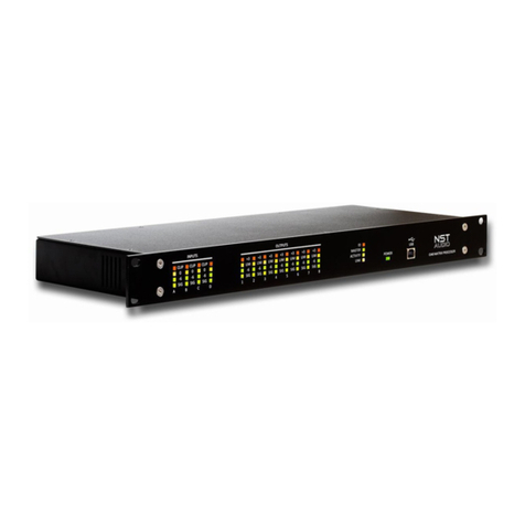
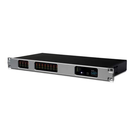
NST Audio D48 User manual

D48S / D48 –Matrix Signal Processors
User Manual
Revision 1.4
www.nstaudio.com
© NST Audio Ltd 2017

2
Contents
Contents Page 2
Declaration of Conformity 3
Important Safety Instructions 4
WEEE and ROHS 5
Thank you, Unpacking and Installation 6
Overview and Key Features 7
Front Panel Overview 8
Rear Panel Overview 9
Front Panel Controls and LCD in Detail 10
Menu Options in Detail 11
D-Net Computer Control Software 12
Technical Specifications 13
Maintenance, Servicing, Warranty and Contact 14

3
EU Declaration of Conformity
This declaration is issued under the sole responsibility of the manufacturer.
The object of the declaration is in conformity with the relevant Union harmonisation Legislation.
NST Audio Ltd
32 Whitewall
Norton
YO17 9EH
England
United Kingdom
accept responsibility that the following products:
Kind of equipment: Audio processor
Model: D48S / D48
are manufactured in accordance with EMC Directive 2014/30/EU,
in compliance with the following technical regulations: EN55103-1:2009, EN55103-2:2009
And in accordance with the Low Voltage Directive 2006/95/EC,
in compliance with technical regulations: EN/IEC60065:2014
Signed:
Name: Dan Cartman
Position: Research and Development Manager
Date: April 2017

4
Important Safety Instructions
Terminals marked the lightning symbol carry electrical current of sufficient magnitude to constitute risk of electric shock. Use only high-quality
cables with plugs pre-installed. All other installation or modification should be performed only by qualified personnel. This symbol, wherever it
appears, alerts you to the presence of un-insulated dangerous voltage inside the enclosure - voltage that may be sufficient to constitute a risk
of shock. This symbol, wherever it appears, alerts you to important operating and maintenance instructions in the accompanying literature.
Please read the manual.
Caution:
To reduce the risk of electric shock, do not remove the top cover (or the rear section). No user serviceable parts inside. Refer servicing to
qualified personnel.
Caution:
To reduce the risk of fire or electric shock, do not expose this appliance to rain and moisture. The apparatus shall not be exposed to dripping or
splashing liquids and no objects filled with liquids, such as vases, shall be placed on the apparatus.
Caution:
These service instructions are for use by qualified service personnel only. To reduce the risk of electric shock do not perform any servicing other
than that contained in the operation instructions. Repairs have to be performed by qualified service personnel.
1. Read these instructions.
2. Keep these instructions.
3. Heed all warnings.
4. Follow all instructions.
5. Do not use this apparatus near water.
6. Clean only with dry cloth.
7. Do not block any ventilation openings. Install in accordance with the manufacturer’s instructions.
8. Do not install near any heat sources such as radiators, heat registers, stoves, or other apparatus that produce heat.
9. Do not defeat the safety purpose of the polarized or grounding-type plug. A polarized plug has two blades with one wider than the other. A
grounding-type plug has two blades and a third grounding prong. The wide blade or the third prong are provided for your safety. If the
provided plug does not fit into your outlet, consult an electrician for replacement of the obsolete outlet.
10. Protect the power cord from being walked on or pinched particularly at plugs, convenience receptacles, and the point where they exit from
the apparatus.
11. Use only attachments/accessories specified by the manufacturer.
12 . Use only with the cart, stand, tripod, bracket, or table specified by the manufacturer, or sold with the apparatus. When a cart is used, use
caution when moving the cart/apparatus combination to avoid injury from tip-over.
13. Unplug this apparatus during lightning storms or when unused for long periods of time.
14 . Refer all servicing to qualified service personnel. Servicing is required when the apparatus has been damaged in any way, such as power
supply cord or plug is damaged, liquid has been spilled or objects have fallen into the apparatus, the apparatus has been exposed to rain or
moisture, does not operate normally, or has been dropped.
15. The apparatus shall be connected to a MAINS socket outlet with a protective earthing connection.
16. Where the MAINS plug or an appliance coupler is used as the disconnect device, the disconnect device shall remain readily operable.
17. Correct disposal of this product: The wheeled bin symbol indicates that this product must not be disposed of with household waste. Please
refer to the WEEE page of this manual.

5
WEEE
Once your NST Audio product has reached the end of its useful life, please ensure that is recycled in a
proper manner.
"The WEEE Regulations 2013 are the UK interpretation of the EU WEEE Directive and aim to reduce the
quantity of waste electrical and electronic equipment (WEEE) disposed of in the UK".
EEE producers are required to pay for the reuse, recycling and recovery of the products by registering as
an EEE producer which requires them to join a producer compliance scheme.
NST Audio has been registered with producer compliance scheme Comply Direct since 2015 ensuring
100% compliance with the WEEE regulations 2013.
Our WEEE Producer Registration Number is WEE/HG5453ZY.
Old electrical equipment can be recycled along with its metal enclosure. Our products are marked with a
crossed-out wheeled bin symbol on the rear of the product.
Please do not throw any electrical equipment (including those marked with the crossed out wheeled bin
symbol) in your general waste bin.
NST Audio Ltd. is able to arrange WEEE collections for our customers through a trusted network of WEEE
recycling facilities made available by Comply Direct. We are able to arrange collection and transportation
of your WEEE to reprocess and recycle ensuring the minimum goes to landfill.
ROHS
The Restriction of Hazardous Substances in Electrical and Electronic Equipment (RoHS) Directive
(2011/65/EU).
NST Audio Ltd products are RoHS compliant, and are available for export as lead-free and RoHS
compliant.
NST Audio Ltd is committed to eliminating the use of hazardous substances in the materials,
manufacturing and packaging of our audio amplifier and other audio products in strict accordance with
the RoHS directive.
With regards to the RoHS Directive 2002 / 95 / EC of the European Parliament and of the Council of 27
January 2003 on the restriction of the use of certain hazardous substances in electrical and electronic
equipment, we declare that to the best of our knowledge, all products meet and fulfil all the
requirements of the aforementioned directive.
All RoHS compliant product shipped will be clearly externally marked as compliant on the packaging.

6
Thank You
Thank you for choosing an NST Audio product for your application. Please spend a little time reading
through this manual, so that you can obtain the best possible performance from the unit.
All NST products are carefully designed and engineered for cutting-edge performance and world-class
reliability. If you would like further information about this, or any other NST product, please do not
hesitate to contact us.
Unpacking the Unit
After unpacking, please check the unit carefully for any damage. If any is found, immediately notify the
carrier concerned - you, the consignee, must instigate any claim.
Please retain all packaging, in case of future re-shipment.
Installation
Electrical Considerations:
The NST device has been manufactured to comply with your local power supply requirements, but before
connecting the unit to the supply, ensure that the voltage (printed on the rear panel) is correct, and that
a mains fuse of the correct type and rating has been fitted.
Make sure power outlets conform to the power requirements listed on the back of the unit.
Damage caused by connecting to incorrect AC voltage is not covered by the warranty.
Mechanical Considerations:
To ensure that this equipment performs to specification, it should be mounted in a suitable rack or
enclosure. When mounting the unit in a rack or enclosure, ensure that there is adequate ventilation. The
cooling fan sucks cool air in through the right side and blows warm air out of the left side of the unit
through the ventilating grills. Take care when mounting other equipment in the same rack.
Operation:
Read all documentation before operating your equipment and retain all documentation for future
reference. Do not spill water or other liquids into or on the unit and do not operate the unit while
standing in liquid. Do not block the fan intake or operate the unit in an environment that could impede
the free flow of air around the unit. If the unit is used in an extremely dusty or smoky environment, it
should be cleaned of any collected debris at regular intervals.

7
Overview
With inputs and outputs switchable in channel pairs between analogue or AES/EBU the D48S and D48
gives you the flexibility you need to integrate into your system. Compressors are available on every input
as well as a high pass filter, 6 bands of parametric EQ, 2* or 3** bands of dynamic EQ, a 28-band graphic
EQ**, and up to 1.3 seconds of delay. Routing to outputs can be configured to either mix-matrix mode,
free-routing or several pre-configured routing options. Flexible channel linking enables quick and easy
configuration of common crossover setups or customised configurations as required. Every output
channel has high and low pass filters, 8* or 10** bands of parametric EQ, up to 1.3 seconds of delay as
well as a new limiter designed to offer the best driver protection with the lowest distortion.
The D48S and D48 run at 96kHz, as standard, but can be switched into 48kHz mode* to take advantage
of 48dB/oct output crossover filters and two* or three** bands of dynamic EQ on both input and output*
channels. Front panel control allows instant mute of any input or output as well as editing of all the most
commonly used parameters and recall of presets.
The Ethernet based computer control software gives you the ability to not only control all the devices on
a network but also to store preset memories and configure systems offline. With Mac and iPad control
too, you can control your system the way that suits you.
[* D48 only] [** D48S only]
Key Features
4 Analogue Inputs, 8 Analogue Outputs
AES Digital Inputs and Outputs with sample rate conversion from 24kHz to 96kHz
Sample rate switchable between 96 and 48kHz (adds DEQ filters and 48dB/Oct crossover filters)*
Input Processing Features:
Soft Knee Compressor
6 Parametric EQs
24dB/Oct HPF
2 bands of Dynamic EQ (48kHz mode)* / 3 bands of Dynamic EQ**
28-band Graphic EQ**
Gain, Polarity, Delay
Routing Matrix Modes:
Mix Matrix, Routing Matrix, Preset Configurations (2x4, 4x2, 1x8, 2x3+2)
Output Processing Features:
8 Parametric EQs* / 10 Parametric EQs**
Crossover Filters up to 48dB/Oct (48kHz mode) 24dB/Oct (96kHz mode)*
2 bands of Dynamic EQ (48kHz mode)*
Gain, Polarity, Delay, Limiter
Remote control via 100Mbps Ethernet, USB Type B
Up to 30 presets may be stored for offline recall

8
Unit Overview
Front Panel Overview:
1. LCD Screen:
2x16 character backlit LCD display, showing various control parameters and menu options.
2. Rotary Encoder:
Velocity sensitive illuminated control adjusts the displayed parameter on the LCD screen.
3. Navigation Keys:
Centre Key: Enters and quits parameter and menu screens - Confirms menu options.
Up Key: Navigates upwards through menu and parameter options.
Down Key: Navigates downwards through menu and parameter options.
Left Key: Navigates left through menu and parameter options containing multiple options.
Right Key: Navigates right through menu and parameter options containing multiple options.
4. Input Meters, Mute Keys and Edit Keys:
Real time LED input meters show level from maximum input level (clip) in 4-segments...
Signal present, 6dB below clipping, 0dB/maximum input level and clip*.
*If analogue input level is within 1dB of clipping, the red input Clip LED will illuminate to show this.
Mute Keys: Mutes the selected input channel and illuminates red to confirm this.
Edit Keys: Accesses the selected input channel’s parameters and illuminates amber to confirm this.
Tip: Pressing an Edit key for a second time will display the last parameter edited, making it easier to
edit or check the same parameter across multiple channels.
5. Output Meters, Mute Keys and Edit Keys:
Real time LED output meters show level from the limiter threshold in 4-segments...
Signal present, 6dB below limiter threshold, Limiter threshold and 3dB into limiting.
Mute Keys: Mutes the selected output channel and illuminates red to confirm this.
Edit Keys: Accesses the selected output channel’s parameters and illuminates amber to confirm this.
Tip: Pressing an Edit key for a second time will display the last parameter edited, making it easier to
edit or check the same parameter across multiple channels.
6. USB port:
USB type B port for single unit connection to a computer running the D-Net software.
7. Comms:
Activity: Flashes when communication is taking place between the device and D-Net software.
Link: Illuminates when a suitable Ethernet connection is established.
Note: Any parameter changes will be reflected to a connected computer running the NST Audio D-Net
software, in real time!

9
Rear Panel Overview:
1. Mains Power Inlet, Fuse and Power Switch:
3-pin IEC input, fused [5mm x 20mm, 3.15A, 250V, Anti-Surge (T)], 90-250VAC, 50-60Hz <40W.
A spare fuse is located within the fuse holder –only replace with the correctly rated fuse!
2. Ethernet Computer Control Port:
Neutrik EtherCON RJ45 network Ethernet port accepts either a standard CAT5 cable or housed RJ45
connector for connection to a computer (or suitable network switch to control multiple units
simultaneously).
3. Balanced Analogue Audio Outputs / Digital AES Outputs*:
The analogue outputs are wired as follows:
Pin 1: Shield/Ground
Pin 2: Signal Hot (+)
Pin 3: Signal Cold (-)
*Digital AES outputs can be enabled from within the D-Net software, and run in pairs...
Outputs 1 and 2 are outputted together from output 1.
Outputs 3 and 4 are outputted together from output 3.
Outputs 5 and 6 are outputted together from output 5.
Outputs 7 and 8 are outputted together from output 7.
4. Balanced Analogue Audio Inputs / Digital AES Inputs*:
The analogue inputs are wired as follows:
Pin 1: Shield/Ground
Pin 2: Signal Hot (+)
Pin 3: Signal Cold (-)
*Digital AES inputs can be enabled from within the D-Net software, and run in pairs...
Inputs A and B are inputted together on input A.
Inputs C and D are inputted together on input C.

10
Front Panel Control and LCD in Detail
LCD Default Mode:
If the menu is not accessed, and no edit keys are illuminated, then by default the top line of the screen
will show the name of the device (editable from the D-Net software).
The bottom line of the screen will show the name of the last stored or recalled preset –an asterisk (*) will
show if any parameter from the original preset has been changed.
Channel Edit Screens:
Pressing any of the Edit keys will access the selected channel(s) parameters.
Use the Up and Down navigation keys to view available parameters.
Use the rotary control to edit any parameter.
If a ‘<’ or ‘>’ appears on the LCD, this shows there are further parameters available to view and edit - by
use the Left and Right navigation keys to access these parameters.
(Please note that not all parameters are available from the front panel –use D-Net for full access!)
Input Parameters:
Assuming the Down navigation key is being pressed, the input parameters will show as follows:
Gain
Phase (Note: This parameter will remain unlinked, if channel links are in use!)
Delay
High-Pass Filter (HPF) Frequency > Type > Bypass
PEQ1 Frequency > Gain > Q > Bypass > Type
PEQ2 Frequency > Gain > Q > Bypass > Type
PEQ3 Frequency > Gain > Q > Bypass > Type
PEQ4 Frequency > Gain > Q > Bypass > Type
PEQ5 Frequency > Gain > Q > Bypass > Type
PEQ6 Frequency > Gain > Q > Bypass > Type
Output Parameters:
Assuming the Down navigation key is being pressed, the output parameters will show as follows:
Gain
Phase (Note: This parameter will remain unlinked, if channel links are in use!)
Delay
Limiter
High-Pass Filter (HPF) Frequency > Type
Low-Pass Filter (LPF) Frequency > Type > Bypass
PEQ1 Frequency > Gain > Q > Bypass > Type
PEQ2 Frequency > Gain > Q > Bypass > Type
PEQ3 Frequency > Gain > Q > Bypass > Type
PEQ4 Frequency > Gain > Q > Bypass > Type
PEQ5 Frequency > Gain > Q > Bypass > Type
PEQ6 Frequency > Gain > Q > Bypass > Type
PEQ7 Frequency > Gain > Q > Bypass > Type
PEQ8 Frequency > Gain > Q > Bypass > Type

11
Menu Options in Detail
Pressing the centre navigation key will access the D48S or D48 menu options.
Assuming the Down navigation key is being pressed, the menu options will show as follows:
System:
LCD Brightness
Adjusts the LCD’s brightness level - values 1 to 32, where 1 is the dimmest and 32 is the brightest.
Use the rotary control to vary the brightness level.
IP Address
Displays the D48’s IP address (for when connecting to a computer running the D-Net software).
MAC Address
Displays the device’s MAC address (for when connecting to a computer running D-Net software).
Firmware Version
Displays the device’s firmware version. To update the firmware, use the D-Net computer software.
Lock Device:
This feature allows the device to be locked with a 4-digit pin code. Once locked, no parameters can be
viewed or edited. If the device is connected to the D-Net software, it will be discovered and will show
metering, but it cannot be accessed unless the correct pin code is entered.
To lock the device:
1. Press the centre navigation key when the menu is showing Lock Device.
2. Use the rotary control to select whether to lock ‘Everything’ or ‘Enable Presets’, meaning the device will
be locked, but will still allow presets to be recalled. Press the centre to key to confirm.
3. The unit will ask for a 4-digit pin code to be entered –use the rotary control to select a number, and
then use the right navigation key to access the next number.
4. Once the 4-digits have been entered, press the right navigation key once more.
5. The unit will then ask to confirm the pin code –re-enter the pin code, as above, and press the right
navigation key to lock the device. The device will only lock if both pin codes match.
To unlock the device, repeat steps 1 to 3.
If a pin code has been inadvertently forgotten, please contact NST Audio.

12
Interface Modes:
Allows the selection of analogue or digital AES options for input and output channels.
Press the centre navigation key, to access the options, and then use the left and right navigation keys to
view the available options. Use the rotary control to edit the options.
See the ‘Rear Panel Overview’ page for details.
Create Xover:
This menu option allows a quick set-up of common crossovers.
Use the rotary control to view the available formats and press the centre key to select the desired format.
Press the centre key once again to confirm the selection.
(For a full selection of routing options and crossover set-up, use the D-Net software).
Recall Preset:
Lists any presets stored within the device. Use the rotary control to view the presets, and then use the
centre navigation key to recall the displayed preset.

13
D-Net Remote Control Application
Windows, Mac and iPad compatible remote control software with USB and Ethernet access.
Full control of all DSP, routing and configuration of multiple NST Audio devices with the ability to set up
systems offline and store/load presets and preset libraries.
Please visit www.nstaudio.com and click on the Software link to download D-Net!

14
Technical Specifications
Analogue Inputs –4
Electronically balanced, pin 2 hot
CMRR: >60dB @ 1kHz
Maximum Level: >20dBu
Input Impedance: 10kΩbalanced
AES Inputs –2 x 2 channel
Transformer balanced, pin 2 hot
AES Input Sample Rates : 8kHz to 96kHz
AES Input s/n Ratio : 139dB
Input Impedance : 110Ω
Analogue Outputs –8
Electronically balanced, pin 2 hot
Maximum Level: >20dBu
Source Impedance: <60Ω
AES Outputs –4 x 2 channel
Transformer balanced, pin 2 hot
Sample Rate : same as operating sample rate
Source Impedance : 110Ω
Performance:
Frequency Response (20Hz to 20kHz): +/-0.4dB
Dynamic Range: >115dB unweighted (in to out analogue)
THD + N (+10dB @ 1kHz): 0.0013%
Latency: 1.074ms (in to out, analogue, 96kHz)
Processing:
Input Gain (per channel) : -30 to +15dB in 0.1dB steps, mute, phase
Input Delay (per channel) : 0 to 1.3s in 10.4uS steps (at 96kHz)
Input Compressor (per channel) : Threshold (-30 to +22 dBu), Attack, Release, Ratio, Soft-Knee
Input Parametric EQ (per channel) : 6 bands –parametric, low shelf, high shelf, notch, band-pass
Input High-Pass Filter (per channel) : Up to 24dB/octave (Bensen/Butterworth/Bessel/Linkwitz-Riley)
Input Dynamic EQ (per channel) : 2* or 3** bands
Input Graphic EQ (per channel) : 28 bands**
Routing Inputs to Outputs: Choice of modes (Matrix Mixer, Free Routing, 1×8, 2×4, 4×2, 2×3+2 Aux)
Output Parametric EQ (per channel) : 8* or 10** bands –parametric, low shelf, high shelf, notch, band-pass
Output Dynamic EQ (per channel) : 2 bands* (48kHz only) –parametric/low shelf/high shelf, boost/cut above/below, threshold,
ratio, attack, release
Output High-Pass and Low-Pass Filter (per channel) : Up to 48dB/octave (Bensen/Butterworth/Bessel/Linkwitz-Riley) at 48kHz*
(up to 24dB/octave at 96kHz)
Output Gain (per channel) : -30 to +15dB in 0.1dB steps, mute, phase
Output Delay (per channel) : 0 to 1.3s in 10.4uS steps (at 96kHz)
Output Limiter (per channel) : Threshold (-50 to +22dBu), attack, release, auto attack/release option
Presets : Up to 30
Power Requirements:
3-pin IEC input, fused [5mm x 20mm, 3.15A, 250V, Anti-Surge (T)], 90-250VAC, 50-60Hz < 40W
Dimensions:
Height: 44mm (1.75inch) 1U, Depth: 213mm (8.4 inches), Width: 482mm (19 inches)
Weight:
Net: 2.8kg, Shipping: 3.9kg
[* D48 only] [** D48S only]
Due to continuing product improvement the above specifications are subject to change.

15
Maintenance
The unit will require very little routine maintenance, apart from occasional routine checking of the fan
inlet outlets on the side panels. Cleaning the casework should only be done with a cloth lightly
dampened with water only! The use of chemical or abrasive cleaners may damage the paint finish.
Servicing
There are no user serviceable parts within the unit!
Please contact us to arrange returning any units to us that require servicing or repairing.
Warranty
This product comes with a warranty against defects in components and workmanship only, for a period
of five years from the date of shipment to the customer. During the warranty period, NST Audio will, at
its discretion, either repair or replace products that prove to be defective, provided that the product is
returned, shipping prepaid, to an authorised NST Audio service facility.
Defects caused by unauthorised modifications, misuse, negligence, act of God or accident, or any use of
this product that is not in accordance with the instructions provided by NST Audio, are not covered by
this warranty.
This warranty is exclusive and no other warranty is expressed or implied.
NST Audio is not liable for consequential damages.
Contact
If you have any questions or comments about the information contained within this manual, or require
further assistance, then please do not hesitate to contact us at www.nstaudio.com
Thank you
The NST Audio team
This manual suits for next models
1
Table of contents
Other NST Audio Signal Processor manuals
Popular Signal Processor manuals by other brands

Imagine communications
Imagine communications Selenio 6800 SFS6803+OP+SFS+ Installation and operation manual

Redback
Redback A 4906 operating manual

Lemco
Lemco Micro line MLF-301 manual

EVS
EVS Synapse GFS100 Installation and operation manual

Vaisala
Vaisala RVP10 Hardware quickguide

miniDSP
miniDSP BALANCED 2X4 user manual