NTC SGUALA' User manual

Manual Code UME-TSG02-07/21 www.newtableconcept.com All rights reserved
SGUALA’
USER MANUAL
NTC srl – Sales Office

UME-TSG02-07/21 www.newtableconcept.com
Page 2
SUMMARY
1. INTRODUCTION ___________________________________________________ 3
2. CONTENT ________________________________________________________ 3
3. PARTS DESCRIPTIONS _____________________________________________ 4
4. REQUIRED TOOLS _________________________________________________ 5
5. WARNINGS _______________________________________________________ 5
6. UNPACKING ______________________________________________________ 5
7. ASSEMBLY _______________________________________________________ 6
8. OPENING AND CLOSING ____________________________________________ 9
9. CLEANING AND MAINTENANCE _____________________________________ 9
10. WARRANTY _____________________________________________________ 10

UME-TSG02-07/21 www.newtableconcept.com
Page 3
1. INTRODUCTION
Dear Customer, thank you for choosing the SGUALA’ sliding table.
The SGUALA’ sliding table is built with high quality materials and extensive attention to details.
We are confident that you will appreciate the value of our product and enjoy its convenient, space-saving
and aesthetic features.
2. CONTENT
A - Rail mounting holes template
B - Rails
C - Parallelogram metal structure
D - Table top
E - Hardware (Fig. 1a)
- 4 sliders with washers and nuts
- 2 closing lock magnets
- 10 M6x45 and 2 M6x15 screws to fix the tabletop
- 12 screws and 12 dowels to fix the rails to the wall (Fig. 1b)
Fig. 1a
Fig.1b
WARNING: The screws and dowels we provide are suitable for walls made of solid bricks or concrete. In all
other cases you must use dowels and screws appropriate for the wall in question.

UME-TSG02-07/21 www.newtableconcept.com
Page 4
3. PARTS DESCRIPTIONS
The table is made up of three main components, which are:
the stainless-steel rails to be fixed to the wall
the variable parallelogram metal structure to be connected to the sliders of the rails
the tabletop to be screwed over the parallelogram metal structure (Fig. 2).
Fig. 2
The four sides of the parallelogram metal structure are formed by the following parts (Fig. 3):
the sliding carriage is attached to the four sliders. It runs up and down 12 mm from the wall
the frame holds the tabletop
the main carriage on wheels
the pair of tie rods.
Fig. 3
The parallelogram metal structure hosts three components:
the counterweight, which is made of metal plates, is located at the end of the frame opposite the
rails (it is not present in short tables)
the piston is located between the main carriage and the frame
the table lock mechanism is located on the right side of the sliding carriage.

UME-TSG02-07/21 www.newtableconcept.com
Page 5
4. REQUIRED TOOLS
The tools you will need are: measuring tape, screwdrivers (electric screwdriver is better), drill, drill bit 6 mm
(1/4”), pencil, 2.5 mm Allen key and an 8 mm wrench (Fig. 4).
Fig. 4
5. WARNINGS
The table will be mounted to the wall which is a fundamental element for table stability in both working and
closed positions. It is important to mount the table on a wall suitable for securing table stability. NTC srl
guarantees table strength but is not responsible for wall failures or unsuitable mounting on the wall.
The sliding carriage slides up and down at a distance of twelve millimeters from the wall. The main
carriage, with the table in closed position, is also located at the same distance from the wall. For smooth
operation of the table, the skirting board cannot have a thickness greater than 12 mm.
If not, the skirting board must be removed for a length equal and corresponding to the width of the main
carriage. The opening and closing of the table are forbidden for children under 12 years old.
6. UNPACKING
The wooden cage is assembled with nails on one side and with screws on the other. The screws need to
be removed to open the cage.
1. Unscrew the cage and remove the wooden bars (Fig. 5 and Fig. 6).
2. Remove the cardboard protection sheet.
Fig. 5 Fig. 6
3. Take out the rail mounting holes template.
4. Take out the screws and dowels bag.
5. Take out the rails located on one side of the table.

UME-TSG02-07/21 www.newtableconcept.com
Page 6
7. ASSEMBLY
1. Decide where you want to have the table and make sure the wall is appropriate for mounting and
can safely hold the weight and stresses to which it will be subjected. The wall must be flat, free of
any obstacles (electrical outlets, air intakes, etc.) and with the height adequate to accommodate the
table size.
2. Place the rail holes template in the position where you like to have the table (Fig. 7). The holes
template has the same size of the table in closed position.
Fig. 7
3. IMPORTANT: The position of the holes in the template is not vertically symmetrical; there is a label
on the template which identifies the side that must be on the top when marking the holes (Fig. 7).
4. Use a pencil to mark the holes for fixing the two rails.
5. Remove the template and make the holes. To obtain a greater precision, we recommend to make
four lines around the circular mark (Fig. 8) and to drill the holes first with a small drill bit and then re-
drill with the 6 mm (1/4”) drill bit to enlarge the holes
6. Insert the dowels into the holes.
7. Screw the two rails to the wall. IMPORTANT: The two rails are not identical. Screw the rail with
the magnet and the side hole (Fig. 9) on the right and the other on the left.
8. Before tightening the guides check that they are parallel, perpendicular to the floor and at a distance
of 680 mm between them.
Fig. 8 Fig. 9
9. After removing the nut and one washer from the sliders, insert them (two for rail) into the rails and
place them at about 2.5 mm and 220 mm from the bottom of the rails using pieces of blue packing
material to keep them in position (Fig. 10).

UME-TSG02-07/21 www.newtableconcept.com
Page 7
Fig. 10
10. Unscrew the four screws that hold the parallelogram structure to the table board during shipping and
collect them for the mounting of the board.
11. In order to facilitate the assembly, it is convenient to move the parallelogram structure opened.
Before taking the structure out from the cage, remove the nylon that holds the two carriages
bounded to the frame and open the parallelogram structure completely by lifting the lower parts of
the main carriage. Because of the piston, the structure will open slowly, and you will need to apply
some effort.
12. In order to lock the parallelogram structure in the open position, insert the gray plastic cylinder with a
slot (located alongside the piston) around the shock shaft and reinforce the plastic cylinder with the
three cable ties (Fig. 11 and 12).
13. Remove the frame from the cage, turn it upside down and position it next to the rails (Fig. 13).
WARNING! Never push or pull the parallelogram structure as it could close with serious
consequences for your hands. Never grab the parallelogram structure at the top of the
sliding carriage as it could crush your fingers in case of accidental closure. Move the
structure by taking it on both sides while lifting it from the floor (Fig. 14).
Fig. 11 Fig. 12 Fig. 13

UME-TSG02-07/21 www.newtableconcept.com
Page 8
Fig. 14 Fig 15
14. Move the structure toward to the rails slightly oblique so that it is closer to one of the two rails.
Starting from the nearest rail, adjust the positioning of the slides so that the screws enter the slots of
the sliding carriage plates pushing the structure further (Fig 15).
15. Insert the washer and screw partially the self-locking nuts to the sliders screws. Repeat the same
operations in the other slider. The self-locking nuts we supply are modified and have a reduced
braking torque. Do not use common self-locking nuts as they may unscrew the sliders screws
when tightening them.
16. Tighten slightly the top nut of the right guide and do not tight the other three (leave one/two
millimeters margin) to allow the screws to move inside the plate slots during the opening and closing
of the table.
17. Fit the two closing lock magnets to the lower ends of the guides. Remove the black rubber cap from
the magnet and loosen the screw just enough to fit the black holder into the guide. Keeping the
holder at the end of the guide, lock it in that position by tightening the screw. Replace the black
rubber cap over the magnet (Fig. 16).
Fig. 16
18. Remove the gray plastic cylinder previously located around the piston shaft.
19. Close the structure lifting it from the wall side or pushing it down from the opposite side and check
that it closes well with the magnets that lock it in that position. Open the structure by pulling it from
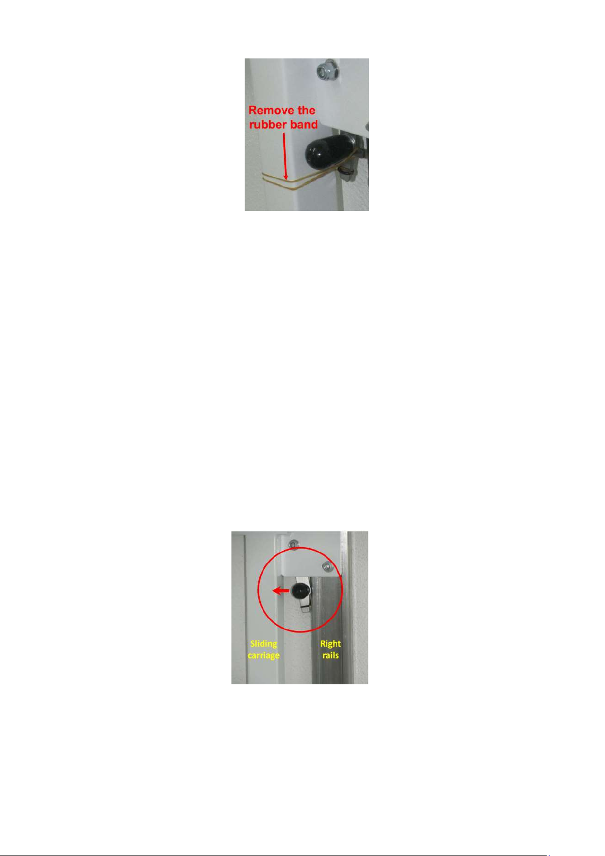
the wall and check that it slides properly. The structure may not open completely due to the lack of
weight. Open it fully by pushing on the sliding carriage.
20. If the structure does not slide properly, you can get better results by loosening or tightening the
slider nuts or by improving the parallelism of the two rails.
21. Activate the locking mechanism by removing the rubber band that holds the locking hook (Fig. 17).

UME-TSG02-07/21 www.newtableconcept.com
Page 9
Fig. 17
22. With the table in open position, make sure that the locking hook is centered horizontally and
vertically with the hole present in the right rail and that it always enters the hole any time you open
the structure.
23. Open and close the structure a few times and check that the locking mechanism is functioning
properly.
24. With the structure open and locked, take the tabletop from the cage and place it over the structure
with the wall side (indicated by the label under the table top) towards the rails.
25. Fix the tabletop to the frame by screwing the M6x45 screws that go along the edges of the table top
and the two M6x15 screws that go to the center of the table top. Tighten the screws slightly.
8. OPENING AND CLOSING
The opening and closing of the table are forbidden for children under 12 years old.
To open the sliding table SGUALA’, simply pull out from the wall the lower part of it for a few tens of
centimeters to the point where it continues to open on its own.
To close the sliding table SGUALA’, push inward the knob of the lock hook located on the right side of the
sliding carriage (Fig. 18) hold it in that position, lift the table up and slide it to its closed position by pushing
the table to the wall. The lock hook knob must be held inward during the first centimeter of the table lifting
and then it can be released.
Fig. 18
9. CLEANING AND MAINTENANCE
The SGUALA’ sliding table does not require special maintenance. Cleaning can simply be done with a
damp cloth or with a standard furniture cleaning product.

UME-TSG02-07/21 www.newtableconcept.com
Page 10
10. WARRANTY
The warranty is valid for two years from shipment date of the product and covers only defective parts or
breakage due to production defects. The warranty does not cover breakage or damage due to improper
use of the table. The broken parts will be replaced free of charge. The shipping expenses will be charged to
the customer.
To make a claim under the warranty, send an e-mail to support@newtableconcept.com with a
description and pictures of the defect.
NTC srl reserves the right to modify the product without any notice.
Table of contents
Other NTC Indoor Furnishing manuals
Popular Indoor Furnishing manuals by other brands

modway
modway EEI-2674 quick start guide

Baby Relax
Baby Relax DA6526 Assembly manual

Home Decorators Collection
Home Decorators Collection FZA71015R-STBC Use and care guide

aspenhome
aspenhome I215-360T Assembly instructions

LDI Spaces
LDI Spaces SAFCO Priya 5075 Assembly instructions

Whittier Wood
Whittier Wood 3816DUET Assembly instructions