NTech Greenseeker 505 User manual

Model 505
GreenSeeker Hand Held™Optical Sensor Unit
Operating Manual
740 South State Street Ukiah, CA 95482
tel 707-467-3747 fax 707-467-3750
toll-free 888-728-2436
www.ntechindustries.com
®

500-1-030 2Rev I: 2006.05.04

500-1-030 3Rev I: 2006.05.04
Table of Contents
The GreenSeeker Hand Held™ Optical Sensor Unit......................................................................... 4
Introduction.....................................................................................................................................................................4
Mechanical Specifications................................................................................................................................................4
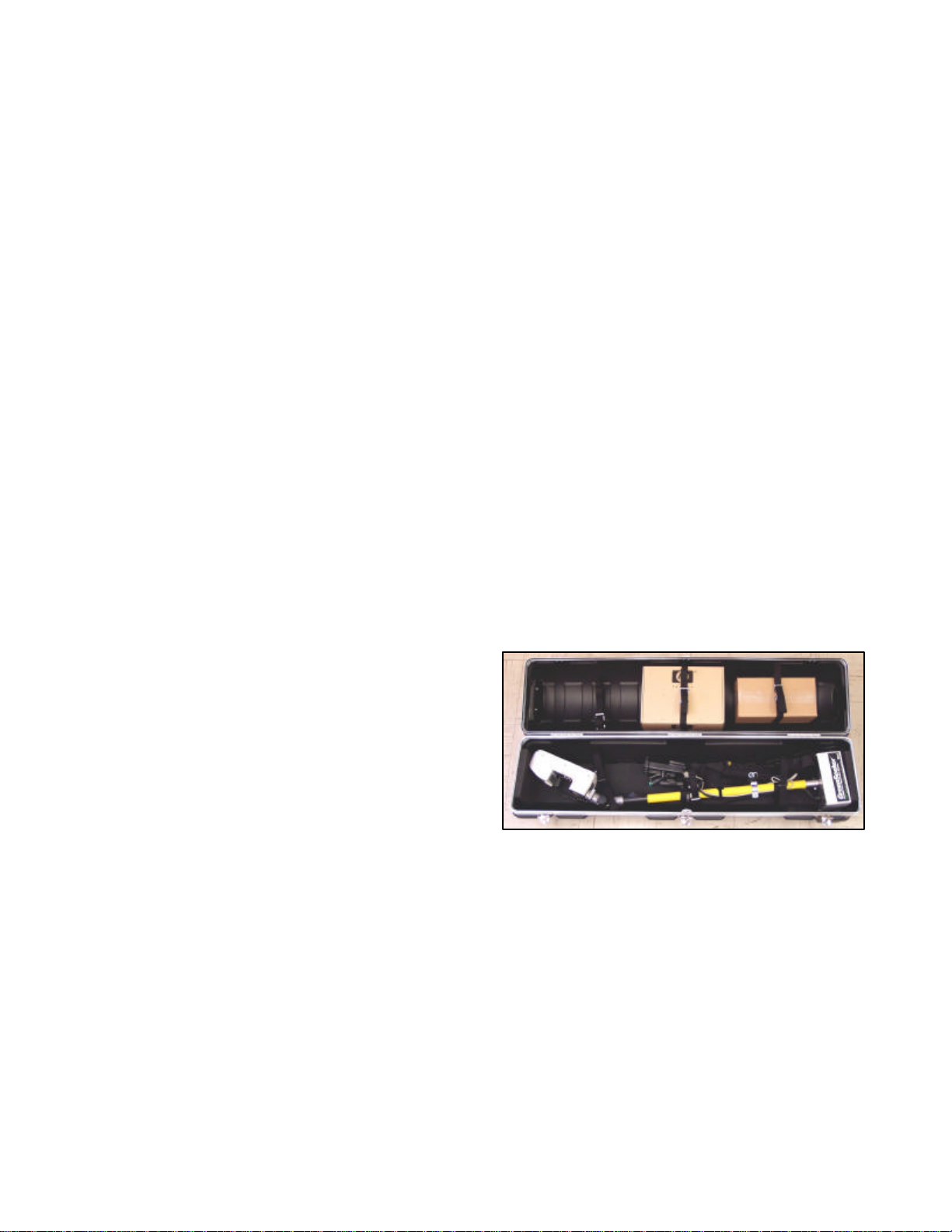
Accessories........................................................................................................................................................................4
GreenSeeker Hand Held -Quick Start.............................................................................................. 5
Primary Components.......................................................................................................................... 6
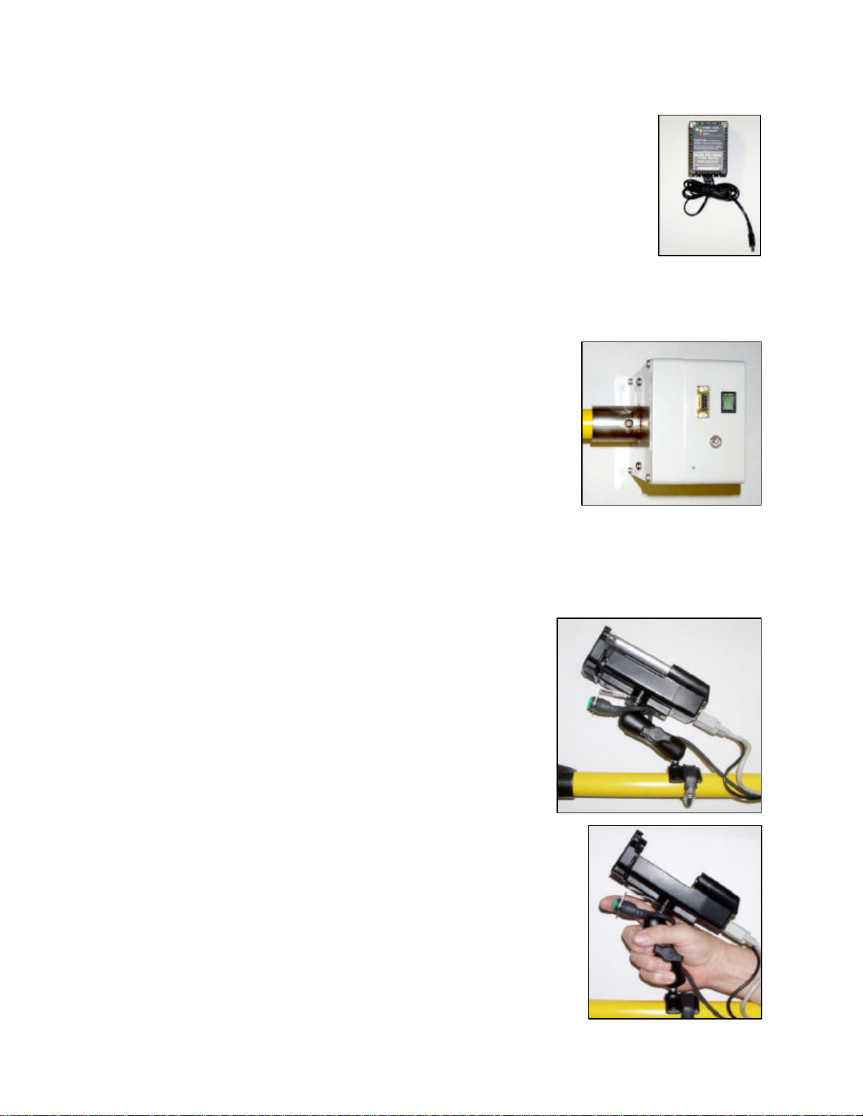
Battery Charger ................................................................................................................................................................6
Control Box......................................................................................................................................................................6
Power Connector .............................................................................................................................................................6
Power Switch/Indicator ...................................................................................................................................................6
External Data Port............................................................................................................................................................6
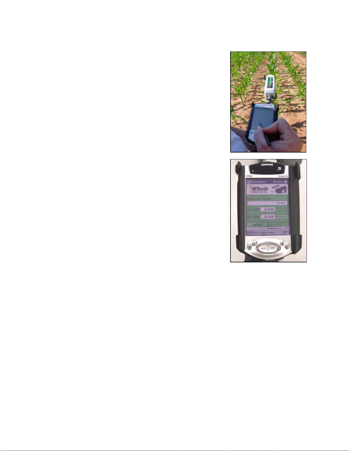
Personal Digital Assistant ................................................................................................................................................6
Powered PDA Cradle .......................................................................................................................................................6
Trigger Switch...................................................................................................................................................................6
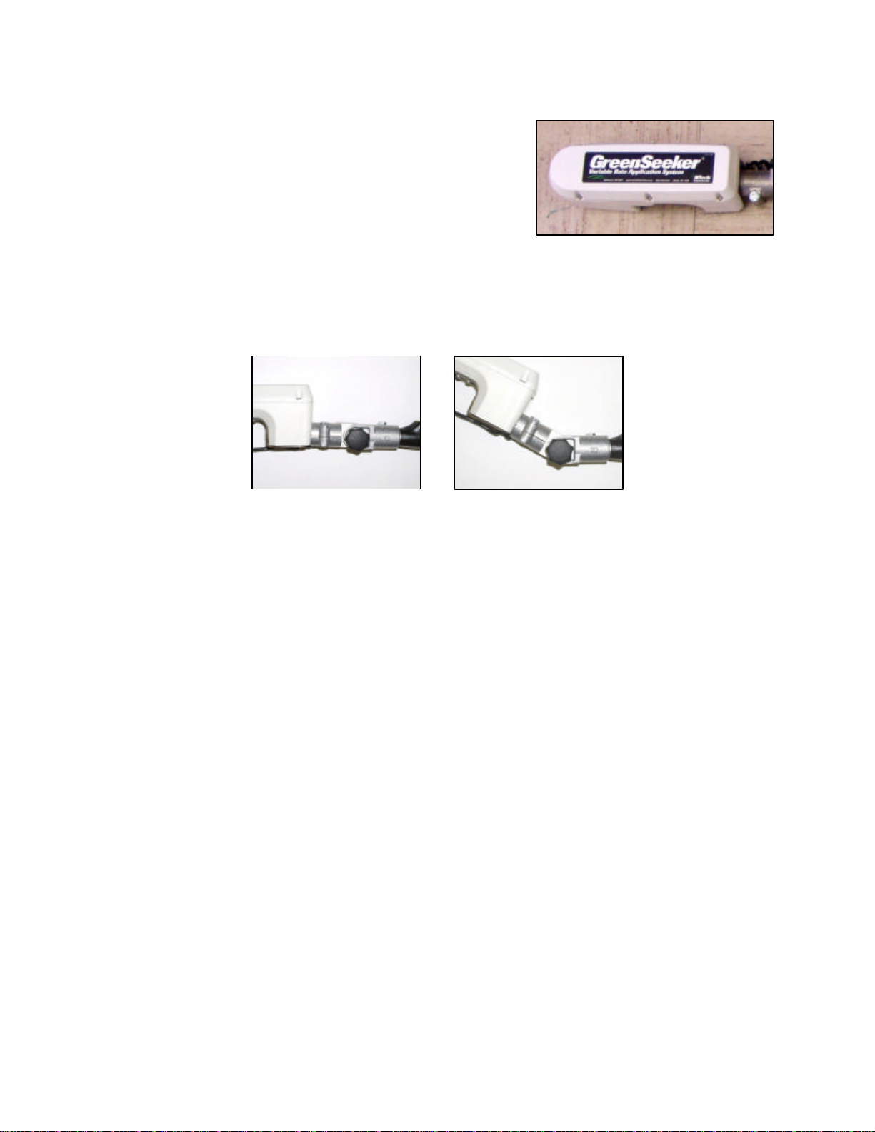
Sensor................................................................................................................................................................................7
Sensor Mount...................................................................................................................................................................7
Telescoping Tube .............................................................................................................................................................7
Connections......................................................................................................................................... 8
Sensor Connection...........................................................................................................................................................8
Control Box to iPAQ Connections .................................................................................................................................8
Wearing the GreenSeeker Hand Held™ Unit..................................................................................... 8
Software Information.......................................................................................................................... 9
Log Strips Mode...............................................................................................................................................................9
Log Plots Mode...............................................................................................................................................................11
Log Plots Mode Data Management...............................................................................................................................12
Helpful Hints ......................................................................................................................................13
APPENDIX A: Data Output Options..................................................................................................15
APPENDIX B: How To Re-install NTech Capture©.........................................................................17
For Pocket PC 2002:.......................................................................................................................................................17
For Pocket PC 2003:.......................................................................................................................................................17
APPENDIX C: Vegetation Indices Available in the GreenSeeker®Sensor..................................18
Index Equations..............................................................................................................................................................18
References.......................................................................................................................................................................18

500-1-030 4Rev I: 2006.05.04
The GreenSeeker Hand Held™ Optical Sensor Unit
Congratulations on your purchase of a GreenSeeker Hand Held™ Optical Sensor Unit. This
manual provides the description and operation of both the Sensor Unit and the data capture
program.
Introduction
The GreenSeeker Hand Held Optical Sensor Unit is a tool for crop research and consulting that
provides precision measurement and data logging of the Normalized Difference Vegetative Index
(NDVI) and Red to Near Infrared Ratios of plant material. These data points can be used in
conjunction with other agronomic references to index basic nutrient response, crop condition,
yield potential, stress, pest and disease impact in a quantitative manner. The unit can be used to
monitor changing field (plant/crop) conditions during the growing season and the effects of
different levels of an input compared to a local standard.
The GreenSeeker Hand Held Optical Sensor Unit utilizes NTech’s second-generation optical
sensor technology. The Unit generates light at two specific wavelengths and measures the light
reflected off the target (typically plants in soil). The microprocessor within the Sensor analyzes
the reflected light and calculates the results. The data from the Sensor is transmitted serially to an
HP iPAQ Personal Digital Assistant, and can later be exported to a desktop computer for analysis.
Mechanical Specifications
•Weight of Unit: approximately 13 pounds (6 kg)
•Weight of Unit, plus case and accessories: approx. 38 lbs (17 kg)
•Case dimensions: 14 x 14 x 51 inches (35.5 x 35.5 x 129.5 cm)
Accessories
•NTech Capture©program for Pocket PC™ 2002/2003
•100-240VAC battery charger
•Polyethylene padded case
(Airline Transportation Association rated)
with wheels and carrying handles

500-1-030 5Rev I: 2006.05.04
GreenSeeker Hand Held -Quick Start
•Insert your iPAQ into the Powered Cradle.
•Place the shoulder strap around body as desired.
•Extend the telescoping tube to desired length, and adjust
Sensor angle so that it is parallel to the sensing area.
•Connect serial cable to the connector on the bottom of the
Powered Cradle and the Control Box.
•Turn on the power to the Sensor (switch is located on the
Control Box).
•Turn on your iPAQ and go to the Start menu. Click on
Programs then the NTech Capture icon to open the
program.
•Select FP_NDVI (Farmer Practice) or RS_NDVI (Nitrogen
Rich Strip) by clicking on Activate. Button will change and
display Monitoring..
•Select Sensor and Start GreenSeeker.
•Position the Sensor at the beginning of the target region.
The Sensor should be roughly parallel to, and 32 to 48
inches above the canopy. Press the trigger switch and
traverse the region. At the region boundary, release the
trigger.
•When the trigger is released the number displayed in the
white box is the average of all readings to that point. Each
press of the trigger logs a new value.
•When you have completed the data collection, go to File
and select Save.

500-1-030 6Rev I: 2006.05.04
Primary Components
Battery Charger
The internal battery, located in the control box, can be recharged using the
battery charger. Simply plug it into the wall, and insert the DC adapter in to the
power supply socket on the control box. The charger’s amber LED will change
to green when the battery is fully charged (100-240VAC in, 12VDC, 800mA
out). The charger will not overcharge the battery.
CAUTION: It is not recommended to connect a vehicle 12V to the power
connector, as there is a risk of over-charging which will damage the internal
battery.
Control Box
The control box contains a battery and a circuit board to interface
the power and switches to the Sensor and external connectors.
Power Connector
This connector goes directly to the battery for charging (12V in).
Power Switch/Indicator
The switch supplies power to the Sensor and Powered Cradle. The
indicator will illuminate when power is on.
External Data Port
The serial port allows the collection of data through an RS232 connection using the serial cable
provided (Com Port: 38,400 Baud, 8, 1, N: Flow: None).
Personal Digital Assistant
The Sensor Unit requires an iPAQ PDA to display and store the
data from the Sensor. Refer to the iPAQ manual for operating
instructions. The NTech Capture©program is pre-loaded on the
iPAQ.
Powered PDA Cradle
This rugged mount securely fastens the PDA to the extension
pole of the Sensor Unit. The Powered Cradle gets its power from
the battery inside the Control Box. It will charge or extend the
battery life of the iPAQ if the Power Switch is turned on.
Trigger Switch
This allows the user to control the data flow and the count of the data
collected. Grip the PDA mount and use index finger to press the
switch. A small buzzer located in the control box will sound while the
trigger switch is pressed. Position the Sensor over the target before
pushing the trigger to avoid erroneous data. (The buzzer can be
disabled. See the “Helpful Hints” section for details.)

500-1-030 7Rev I: 2006.05.04
Sensor
The reflectance readings are taken in this unit. This unit uses
internal illumination for use in any lighting condition, day or
night. When the unit is on, a red band of light will be
observed immediately below the rectangular Sensor window.
The Sensor is designed to be 32 to 48 inches over the desired
plant/crop canopy to be sensed. The width of the Sensor
measurement is a constant 24 inches. This width does not
change with height.
Sensor Mount
The Sensor is adjustable in 15 degree increments. Adjust the angle and the pole length to set the
Sensor parallel to the target. The Sensor must be angled to fit in the storage case.
Telescoping Tube
The telescoping tube is used to position the Sensor for different types of vegetation. It can be held
at higher angles for tall crops, or lower angles for short vegetation, such as newly emerging wheat
or turf grasses. The button located near the Sensor mount swivel is used to extend or retract the
tube.

500-1-030 8Rev I: 2006.05.04
Connections
Verify the connections between the Sensor, the battery pack and the PDA per the figures below.
Sensor Connection
A 12-pin connector mates to the Sensor with two captive screws. Be sure it is mounted in the
lower port shown below. Do not connect to the adjacent connector port.
Control Box to iPAQ Connections
The Control Box is connected to the Powered Cradle/iPAQ with a DB9 (RS232) serial cable. The
small black power cable must be plugged in for the Powered Cradle to get its power from the
battery inside the Control Box.
Wearing the GreenSeeker Hand Held™ Unit
There are three main pieces that may be adjusted for a comfortable fit. The shoulder strap adjusts
in length. Use this strap to distribute the weight of the Sensor to the body. The strap works best
when it is placed diagonally across the body.
The shoulder strap mount is also adjustable. Move the connection back and forth on the
telescoping tube to balance it.
The PDA mount and mount handle may also be changed. The handle may be removed and
turned around so the knob is suitably oriented for left-handed operation. The PDA mount may
also be loosened to change its position along the telescoping tube. By optimizing the position of
these items for comfort, data collection in the field becomes easier.

500-1-030 9Rev I: 2006.05.04
Software Information
NTech Capture©is a software program developed to capture the
readings from the GreenSeeker Hand Held Sensor, display the current
reading, and store them for later data analysis or to make fertilizer
recommendations. Prior to shipment, the software was loaded onto
your iPAQ.
NOTE: If the battery of the iPAQ discharges completely, you will have
to reload the software.
The software is designed to operate like most Windows programs.
Saving and opening a new file are similar to the operation of a word
processing program. Make certain you note where you save the files
on the iPAQ.
There are two modes available for logging data:
Log Strips or Log Plots
The strip logging mode is for collecting sensor readings from large strips with different fertilizer
levels. More specifically, it is for comparing nitrogen rich strips (NRS_NDVI) with lower rate,
farmer practice strips (FP_NDVI) to determine recommendations.
The plot logging mode is for collecting readings from multiple “plots” and is better suited to data
analysis.
Log Strips Mode
To Log Strips:
•Turn on the power switch located on the Control Box.
•Turn on your iPAQ and go to the Start menu. Click on
Programs then the NTech Capture icon to open the
program.
•Select FP_NDVI (Farmer Practice) or RS_NDVI
(Nitrogen Rich Strip) by clicking on Activate. Button will
change and display Monitoring..
•Select Sensor and Start GreenSeeker.
•Position the Sensor at the beginning of the target region.
Press the trigger and traverse the region. At the end,
release the trigger. Data will be recorded to the file when
the trigger is pressed.
•When the trigger is released the number displayed in the
white box is the average of all readings to that point.
•When you have completed the data collection, go to File and select Save.

500-1-030 10 Rev I: 2006.05.04
Data: Log Strips Mode
Once saved, you can view the data collected by simply selecting the name of the file in the
“Field/File Name:” box.
The filename.txt file contains three pieces of information:
Average FP_NDVI value
Average RS_NDVI value
Maximum NDVI from the rich strip (RS).
The data displayed can be used to generate a nitrogen recommendation when used in
conjunction with the Oklahoma State University webpage:
http://www.soiltesting.okstate.edu/SBNRC/SBNRC.php
If you switch between modes and you have not saved the data file, you will be prompted to save
the file.
NOTE: Once you switch modes or close the program you cannot open an existing file and save
more measurements to it. After saving a data file, you can create a new file by selecting File and
New. This will clear the data cells and allow you to collect readings for a new field.
The following is a sample of the text file for reference:
filename.txt
FP_NDVI:
---------------------
AVG = 0.67112, STDEV = 0.11562
RS_NDVI:
---------------------
AVG = 0.77964, STDEV = 0.01023
MAX_NDVI:
---------------------
Max_NDVI = 0.77740

500-1-030 11 Rev I: 2006.05.04
Log Plots Mode
To Log Plots:
•Turn on the power switch located on the Control Box.
•Turn on your iPAQ and go to the Start menu. Click on
Programs then the NTech Capture icon to open the
program.
•Select Sensor and Start GreenSeeker.
•Click on the Log Plots tab.
•Position the Sensor at the beginning of the target region.
Press the trigger and traverse the region. At the end,
release the trigger. Data will be recorded to the file when
the trigger is pressed.
•When the trigger is released the software will display:
oSample No.
oNDVI
oRed/NIR Ratio
oAvg NDVI
oAvg Ratio
•Each time you press the trigger switch the plot increments by one.
•When you have completed the data collection, go to File and select Save.
Data: Log Plots Mode
Three files are created when data is saved. Each file is automatically saved to the following folder:
My Device\My Documents\NtechCapture.
filename.txt file contains all of the data collected
filenameAvg.txt file contains only an average NDVI for each sample (plot)
filenameDiag.txt contains all the diagnostic information for the sensor
If you switch between modes and you have not saved the data file, you will be prompted to save
the file.
NOTE: Once you switch modes or close the software you cannot open a created file and save
more measurements to it. After saving a data file, you can create a new file by tapping File and
New (similar to Log Strips mode). This will clear the data cells and allow you to collect readings
for a new field.

500-1-030 12 Rev I: 2006.05.04
Log Plots Mode Data Management
The data collected with the GreenSeeker Hand Held may be written to the iPAQ’s internal
memory or a removable memory card. It can then be exported to your PC by syncing the iPAQ
with your computer.
Filename.txt and filenameAvg.txt are written to a comma-delimited ASCII text file suitable for
direct import to Microsoft Excel.
•Download the data file(s) to your computer by syncing the iPAQ with your computer.
•Then launch Excel and select Open from the File menu.
•Change File Types to All Files and select your .txt data file.
•Select Delimited Text, delimited by commas and spaces. This will import data into separate
columns in the spreadsheet file.
CAUTION: If the iPAQ has not been charged for several days, the captured data on the iPAQ
may be lost. It is critical that you copy the data from the iPAQ and save it to your PC or a memory
card.
The following is a sample of the text files for reference:
filename.txt
Time(ms),Smpl,Cnt,NDVI,selected_VI,
11000, 0, 17, 0.700, 0.171
11100, 0, 18, 0.730, 0.156
11200, 0, 19, 0.720, 0.157
11300, 0, 20, 0.740, 0.148
11400, 1, 1, 0.740, 0.149
11500, 1, 2, 0.730, 0.156
11600, 1, 3, 0.730, 0.153
11750, 1, 4, 0.720, 0.156
11800, 1, 5, 0.720, 0.161
filenameAvg.txt
GS Time(ms),Sample,Count,NDVI,selected_VI
18570,1, 12,0.78517,0.78517
21570,2, 13,0.78031,0.78031
24570,3, 9,0.77944,0.77944
filenameDiag.txt
*** Sensor Summary ****************
Model.........: 500/505
Hardware Rev..: G*-J/B-D J
Software Ver..: 1.6.6
Compiled......: Feb 14 2005
Serial Num....: J1019
Module Addr...: [19]
Sensor Mode...: [HH]

500-1-030 13 Rev I: 2006.05.04
Helpful Hints
•CAUTION: If the iPAQ has not been charged for several days, the captured data on the
iPAQ may be lost. It is critical that you pull the data off the iPAQ and save it to your PC or
a memory card.
•Charge both GreenSeeker Hand Held™ and iPAQ batteries completely before going to the
field. The internal battery is fully charged when the charger LED is green. The iPAQ
battery is fully charged when the amber LED is on solid.
•Make sure to clear enough memory on your iPAQ before going to the field.
•Make sure the Sensor is approximately parallel to the area being sensed.
•Adjust the shoulder strap and PDA mount so the Sensor can be held comfortably.
•Before going to the field, test the Sensor using the steps outlined in the Sensor
Performance section.
•To disable the buzzer:
1. Open the Control Box by removing the four screws in the corners with a Phillips head
screwdriver.
2. Carefully separate the two halves of the box making sure the cables remained plugged
in.
3. Remove the black jumper from J5 on the yellow connector PCB (ASSY 400-1-014).
4. Close the Control Box and reinstall the four screws.
•If you do not have a current version of Microsoft ActiveSync, go to
http://www.microsoft.com/downloads/ and select ActiveSync from the
“Product/Technology” pull-down menu. Follow the instructions for downloading and
installing the software.

500-1-030 14 Rev I: 2006.05.04
Design Revisions
Continuing a policy of research and development, NTech Industries, Inc. and its subsidiaries
reserve the right of price, product or design changes without notice of obligation.
Software License
THIS PRODUCT INCLUDES SOFTWARE THAT IS ONLY PROVIDED UNDER THE TERMS
OF THE ENCLOSED SOFTWARE LICENSE AGREEMENT. YOU MUST ACCEPT THE
ENCLOSED SOFTWARE LICENSE AGREEMENT BEFORE YOU CAN USE THIS PRODUCT.
IF YOU DO NOT ACCEPT THE TERMS OF THE SOFTWARE LICENSE AGREEMENT, YOU
SHOULD PROMPTLY RETURN THE PRODUCT FOR A FULL REFUND.
Disclaimer
The NTech Industries, Inc. products can be used to determine rates and apply several materials to
various crops and plants. However, results vary depending on factors outside NTech’s control
such as weather, soil conditions, etc. NTech and its distributors make no guarantees regarding
the results you may obtain from the use of this equipment.NTech and its distributors will not be
liable for any consequential damages incurred by the use of NTech products, including but not
limited to loss or reduction in crop yields, or changes in the amounts and expenses of crop
fertilizers or other input materials.
U.S. Patent No: 5,585,626 5,296,702 5,389,781
NTech Industries, Inc.
740 South State Street Ukiah, CA 95482
tel 707-467-3747 fax 707-467-3750
toll-free 888-728-2436
www.ntechindustries.com

500-1-030 15 Rev I: 2006.05.04
APPENDIX A: Data Output Options
For special applications, the user can change the output of the Sensor. From the Outputs Menu,
you can change the speed, format, and type of data. Some of these options are not compatible in
Capture, but are useful for proprietary data logging systems.
Connect the serial cable to a null modem adapter (available at most electronics store or can be
purchased from NTech, p/n 350-6-077) then to a PC’s available serial port. Run HyperTerminal
with the following Com port settings:
38,400 Baud, Data bits: 8, Parity: None, Stop bits: 1, Flow Control: None.
Turn on the Sensor and the following header will display:
*** Sensor Summary ****************
Model.........: 500/505
Hardware Rev..: G*-J/B-D J
Software Ver..: 1.6.6
Compiled......: Feb 14 2005
Serial Num....: J
Module Addr...: [01]
Sensor Mode...: [HH]
Type “m” to bring up the Main Menu:
--- M A I N M E N U -------------------
c. AutoCalibrate [2PT]
u. Select HH or APP ....: [HH]
s. Set Sensor Address ..: [85]
p. Print Parameter Summary
o. OUTPUTS Menu
e. EXTRAS Menu
d. DIAGNOSTICS Menu
q. Quit
Type ‘o’ to select the Outputs Menu.
CAUTION: You should not need any of the other menu functions. Especially,do notselect
AutoCalibrate,as thesensor would losethe calibration,and no longerfunction correctly;it would
thenneed tobe returnedto thefactory.
For special applications, the user can change the output of the Sensor. Type “o” to bring up the
Outputs Menu:
--- O U T P U T S M E N U -------------
1. Set Data output interval ..: 100ms
2. Set Data Smoothing Value ..: 1
3. Select Output Variables ...: [Standard]
4. Select Data Delimiter .....: [comma]
5. Select Vegetation Index ...: [NDVI]
6. Enable Graphing Mode ......: [OFF]
9. Reset all modes to default
m. MAIN menu
q. Quit

500-1-030 16 Rev I: 2006.05.04
1. Data Output Interval ranges from 20ms to 1500ms (50Hz -0.33Hz). This output interval
might be decreased to gather data faster, which is useful if moving at higher speeds. It may
be increased to match other data logging equipment or to limit the amount of data
gathered.
2. Data Smoothing may occasionally be useful to smooth (filter) the data in a highly variable
environment. A setting of 1 is normal output; higher values average the data over longer
intervals.
3. Output Variables. For higher throughput on the port, the output stream may be reduced
to simply NDVI only as a 3-digit integer instead of the five data fields normally output.
4. The Data Delimiter option can change the data output text file to either comma or tab
delimited. Tab delimited is much easier to import into Microsoft Excel.
5. Vegetation Index. Two values are generally supplied by the Sensor. The first output is
always NDVI. The second output may be selected: NDVI, SA-NDVI, WDR-NDVI, RVI,
IRVI. See Appendix C for an explanation.
6. Graphing Mode. Useful primarily for testing, but allows a graph and min-max ranges to
be seen on screen, and makes trends in the data more obvious.
7. Reset to Defaults. Changes all of the modes back to a standard condition, compatible with
the PDA Capture program.
Press “m” to return to the Main Menu or press “q” to quit, putting the Sensor back in the mode
to output data.

500-1-030 17 Rev I: 2006.05.04
APPENDIX B: How To Re-install NTech Capture©
First, you will need to determine what version of Windows Mobilefor Pocket PC Operating
System you are running. Currently there are two different versions: Pocket PC 2002 (WinCE 3.x)
and Pocket PC 2003 (WinCE 4.x). To determine which Pocket PC version is installed on your
iPAQ:
•Find the small decal attached to the back of the iPAQ with the Operating System version
and a serial number written on it, or
•Turn on the iPAQ:
Click: Start -> Settings -> System -> About
The About screen displays:
"Microsoft Pocket PC Version x.x.x..."
Pocket PC 2002 is indicated by Version 3.x.x
Pocket PC 2003 is indicated by Version 4.x.x
For Pocket PC 2002:
•Connect your iPAQ PDA to your computer using Microsoft ActiveSync.
•Once Microsoft ActiveSyncindicates that the iPAQ is connected, insert the NTech
Capture©CD into your computer.
•From the Windows Taskbar, select Start | Run. Once the Run window opens, type:
D:\NTech Capture\2002\Install.exe (where D: is the CD drive)
•If prompted to overwrite a file on the iPAQ, select <Yes To All>.
•Press the soft-reset button on the iPAQ (located on the bottom or rear of the iPAQ).
For Pocket PC 2003:
•Connect your iPAQ PDA to your computer using Microsoft ActiveSync.
•Once Microsoft ActiveSyncindicates that the iPAQ is connected, insert the NTech
Capture©CD into your computer.
•From the Windows Taskbar, select Start | Run. Once the Run window opens, type:
D:\NTech Capture\2003\Install1.exe (where D: is the CD drive)
•The Microsoft VB Runtimes Installer window will open. Click on the Next button and
follow the on-screen instructions.
•From the Windows Taskbar, select Start | Run. Once the Run window appears, type:
D:\NTech Capture\2003\Install2.exe (where D: is the CD drive)
•The NTech Capture Installer window will open. Click on the Next button and follow the
on-screen instructions.
•If prompted to overwrite a file on the iPAQ, select <Yes To All>.
•Press the soft-reset button on the iPAQ (located on the bottom or rear of the iPAQ).

500-1-030 18 Rev I: 2006.05.04
APPENDIX C: Vegetation Indices Available in the GreenSeeker®Sensor
There are several vegetation indices defined, evolving from more than thirty years of research in
remote sensing and aerial imaging. In precision agriculture applications, two of the most
commonly used indices are the Ratio and the Normalized Difference (NDVI), each comparing
the relative reflectance of plant material and soils at two wavelengths. Additional modifications of
the indices have been developed to compensate for various conditions of the plant canopy and
background soil.
Several indices are available from the NTech GreenSeeker®Sensors. The sensor always outputs
NDVI, plus an additional index (default is IRVI), which makes it possible to compare indices on
the same data at the same time. This can be changed by connecting the sensor directly to a
computer. Once selected, the output options are stored in the sensor, and remain in effect until
explicitly changed.
NDVI NormalizedDifference VegetationIndex
SA-NDVI Soil Adjusted
WDR-NDVI Wide Dynamic Range
RVI Ratio
IRVI InverseRatio
Index Equations
The wavelength bands are in the visible and infra-red (NIR) regions of the spectrum. Sensors are
available in both Red and Green varieties, with bands centered at 530nm and 660nm, and the
NIR band centered at 770nm. Half-power bandwidths are approximately 25nm.
VISNIR
VISNIR
ndvi ρρ ρρ +
−
=VIS
NIR
rvi ρ
ρ
=
(
)
(
)
Lndvisa L
VISNIR
VISNIR += ++−1
ρρ ρρ NIR
VIS
irvi ρ
ρ
=
VISNIR
VISNIR
a
a
ndviwdr ρρ ρρ +
−
=
The ‘a’ and ‘L’ values for the SA and WDR indices, respectively, are entered and stored in the Sensor.
SA-NDVI reverts to NDVI if L = 0, and WDR-NDVI reverts to NDVI if a = 1. A typical value for a
is 0.1; a typical value for L is 0.5.
References
University of Sheffield Remote Sensing: GEO6370 Vegetation Indices
http://www.shef.ac.uk/~bryant/6370/veg/vegsoil.htm
U.S. Water Conservation Laboratory: How a Vegetation Index Works
http://www.uswcl.ars.ag.gov/epd/remsen/Vi/VIworks.htm
Mark Servilla: The First Steps to Understanding Agriculture Remote Sensing
http://www.eomonline.com/modernagsite/archives/Servilla.html
USGS: Wide Dynamic Range VI application
http://www.gap.uidaho.edu/Bulletins/12/The Wide Dynamic Range Vegetation Index.htm
BGR: A Comparison of Slope-Based Vegetation Indices for Agricultural Applications
http://www.biogeorecon.com/vegindcs.htm

500-1-030 19 Rev I: 2006.05.04
NTech Industries, Inc.
740 South State Street Ukiah, CA 95482
tel 707-467-3747 fax 707-467-3750
toll-free 888-728-2436
www.ntechindustries.com
Table of contents