manuals.online logo
Brands
  1. Home
  2. •
  3. Brands
  4. •
  5. Ntron
  6. •
  7. Switch
  8. •
  9. Ntron ESERV-M12T User manual

Ntron ESERV-M12T User manual

ESERV-M12T-1210 R2
820 S. University Blvd., Suite 4 E, Mobile, AL 36609 USA
251.342.2164
www.n-tron.com
Copyright, © N-Tron Corp., 2010
C
Ch
he
ec
ck
k
f
fo
or
r
A
Al
ll
l
R
Re
eq
qu
ui
ir
re
ed
d
H
Ha
ar
rd
dw
wa
ar
re
e
ESERV-M12T module
This Quick Start Guide
CD with Modbus Gateway Manager s/w and manuals
Network Cable(s) (not included)
Serial Cable(s) (not included)
Power Supply (not included)
S
Se
et
tu
up
p
t
th
he
e
M
Mo
od
db
bu
us
s
G
Ga
at
te
ew
wa
ay
y
S
So
of
ft
tw
wa
ar
re
e
Open the Modbus Gateway Software: click
StartProgramsN-TRON Modbus Gateway
ManagerConfiguration Manager.
The Device Discovery page opens.
.
L
Lo
og
gi
in
n
Click Login. Password is blank from factory, no
password is necessary to operate the ESERV-M12T.
The Configuration/General page appears.
Quick Start Guide
ESERV-M12T Modbus
Gateway
I
In
ns
st
ta
al
ll
l
t
th
he
e
H
Ha
ar
rd
dw
wa
ar
re
e
Connect a 10 to 58 VDC power supply (Sold
separately). 4W for ESERV-M12T
Connect the top RJ45 connector to a network drop
using a standard network cable (lower RJ45 is pass-
through Ethernet on the model shown below).
Connect the serial device(s):
oRS-232 with DB9: straight-through for DCE
device, null modem for DTE device.
oRS-232/422/485 with terminal blocks: see
Appendix D for pin outs.
2
1
L
LE
ED
D
S
St
ta
at
tu
us
s
LED
STATUS
Ready
Blinks if system is operating correctly, once per second
normally or three times per second for configuration mode
or when reset to factory defaults.
Port 1/
Port 2
On indicates serial port open, blinks when data present
E1
On indicates Ethernet has a link, blinks with data traffic
3
M
Mo
od
de
e
S
Sw
wi
it
tc
ch
h
Hold in Mode switch for…
Result
0 to 2 seconds
Initiates a Hardware Reset
2 to 10 seconds
Enters Console Mode
Over 10 seconds
Reset to Factory Defaults
4
I
In
ns
st
ta
al
ll
l
M
Mo
od
db
bu
us
s
G
Ga
at
te
ew
wa
ay
y
S
So
of
ft
tw
wa
ar
re
e
Insert the included CD and it should auto start.
Follow the prompts to install the Modbus Gateway software.
Note: Be sure you have administrative rights & disable firewalls
in Windows XP
5
6
NOTE: If the device does not connect, cycle (unplug-
replug) the power, then try again to connect.
To configure via the network, select Network.
If you know the IP address, select “The device is at this
address,”and type in the IP address.
If not, select I don’t know the IP address of the device.
Click Connect.
O
OR
R…
…S
Se
et
tu
up
p
t
th
he
e
W
We
eb
b
I
In
nt
te
er
rf
fa
ac
ce
e
Open a browser and type the IP address of the
Modbus Gateway in the Address Bar.
When the Modbus Gateway is found, the Login window
appears.
7
ESERV-M12T-1210 R2
820 S. University Blvd., Suite 4 E, Mobile, AL 36609 USA
251.342.2164
www.n-tron.com
Copyright, © N-Tron Corp., 2010
S
Se
et
tu
up
p
N
Ne
et
tw
wo
or
rk
k
I want DHCP is preselected to set up the network using
dynamic IP addressing. The Modbus Gateway is set up at
the factory to receive an IP assignment from a DHCP
Server. If a DHCP Server is not available on your network, it
will default to 169.254.102.39.
If a DHCP server is not available and the default address
does not work on your PC, change your PC network
settings to IP Address: 169.254.102.1, Subnet Mask:
255.255.0.0, Default Gateway: 169.254.102.100. If you are
not able to use these settings in your installation, refer to
the user’s manual for directions to change the Modbus
Gateway’s TCP/IP settings.
S
Se
et
tu
up
p
M
Mo
od
db
bu
us
s
T
TC
CP
P
Modbus TCP Settings:
Connect to Port identifies TCP port used in TCP client
mode. Valid range is 1 to 65535.
Response timeout is the maximum response time. Valid
range is from 1 to 65535.
TCP Server Settings:
Listen on port identifies TCP port in TCP server mode.
Valid range is from 1 to 65535.
Limit the number of connections…Controls the number of
simultaneous TCP clients that can be connected.
“…allow everyone,” “…allow specific IP address” &
“allow a range of IP addresses” are Connection Filter
Mode options, controlling which TCP clients can connect.
S
Se
et
tu
up
p
P
Po
or
rt
t
1
1
S
Se
er
ri
ia
al
l
Change the Description of the serial port if needed.
Set the Mode to RS-232, RS 422 (4 wire), RS 485 (2 wire)
or RS 485 (4 wire).
Set the Baud Rate to control the speed of the port. Valid
speeds range between 75 and 230,400 bits per second.
Set Data Bits to control the number of bits in each
character. Only 8 bits is valid when the protocol of the
device connected to the port is RTU.
Stop Bits controls the number of bits for end of character.
Parity controls the error checking mode, with options of No
Parity, Odd, Even, Mark and Space.
S
Se
et
tu
up
p
P
Po
or
rt
t
1
1
M
Mo
od
db
bu
us
s
Select the Attached as Master or Slave.
Select the Modbus protocol to be used, either RTU or
ASCII.
As needed, check option boxes for “Enable Modbus
broadcast, “Enable OBh Exception” and “Enable
serial message buffering.”
Select from 0 to 5 Modbus Serial Retries.
Enter Milliseconds Modbus Message Timeout, from 1
to 65535.
Enter Milliseconds TX Delay, from 1 to 65535.
Set up “Port 2 Modbus” the same, only if it has a Port 2.
S
Se
et
tu
up
p
P
Po
or
rt
t
1
1
I
ID
D
R
Re
em
ma
ap
p
Only use this screen if Modbus Slave IDs are to be
remapped.
On each line select a range of serial ports to remap. In the
1st box enter the first serial port of the range to remap
From. Valid port IDs range from 1 to 255.
2nd box - enter the last serial port of the range to remap.
3rd box - enter starting ID of the range to remap To.
The 4th box auto fills based on ranges entered in the first
three columns.
Set up “Port 2 Remap” the same, only if it has a Port 2.
S
Se
et
tu
up
p
M
Mo
od
db
bu
us
s
I
ID
D
R
Ro
ou
ut
ti
in
ng
g
Only use this screen if Modbus Slave IDs are to be re-
routed.
On each line select the range of IDs to re-route. In the 1st
box enter the starting ID. Valid IDs range from 1 to 255.
2nd box –enter the last ID of the range to re-route.
3rd box - enter the IP Address or Port that has slave
devices attached.
The 4th box shows the IP address of the slave device, if
an IP address is chosen in the third box.
S
Se
et
tu
up
p
M
Mo
od
db
bu
us
s
P
Pr
ri
io
or
ri
it
ty
y
Only use this screen if Modbus Priority is to be set.
Enter up to five different priorities, based on Originating IP
Address, Modbus ID, Modbus Function Code, or a
combination of these.
IP Address sets a static IP address for the Modbus
gateway.
Modbus ID has a valid range from 1 to 255.
Function Code has a valid range from 1 to 99.
S
Sa
av
ve
e
a
an
nd
d
L
Lo
og
go
ou
ut
t
If you have completed the configuration, click Save to save
the configuration to the serial server.
To Logout, click the Logout button.
T
To
o
T
Te
es
st
t
a
an
nd
d
V
Ve
er
ri
if
fy
y
O
Op
pe
er
ra
at
ti
io
on
n
The primary check for correct operation is the device
LEDs. See Section 3 this document for more information.
For advanced information, see the Modbus Configuration
Manager menu, at the top of Modbus Gateway Manager
screen.
Select Diagnostic for a check of communications status
with attached ESERV-M12T device, and then select the
device for which the communications check is desired.
A report of reply times and ping statistics is generated and
can be saved.
Select Monitor to review activity logs of attached ESERV-
M12T devices, then select the device for which logged
information is needed
Logged information includes Time, Source & Destination,
Type of event, Subscriber ID, Data collected, and
Information the Modbus Gateway Manager program has
gathered since current login of the affected device.
8
13
14
15
16

Other manuals for ESERV-M12T

1

Other Ntron Switch manuals

Ntron 608MFX-ST Manual

Ntron

Ntron 608MFX-ST Manual

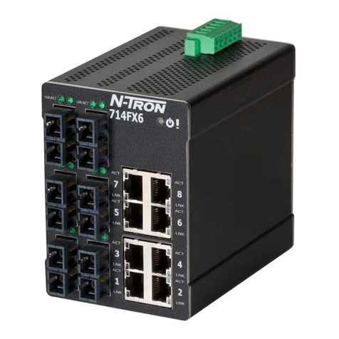
Ntron 714FX6 Series Installation and operating instructions

Ntron

Ntron 714FX6 Series Installation and operating instructions

Ntron 300 User manual

Ntron

Ntron 300 User manual

Ntron NT24k User manual

Ntron

Ntron NT24k User manual

Ntron 604MFX-ST Manual

Ntron

Ntron 604MFX-ST Manual

Ntron 7018TX Installation and operating instructions

Ntron

Ntron 7018TX Installation and operating instructions

Ntron 608MFX-ST User manual

Ntron

Ntron 608MFX-ST User manual

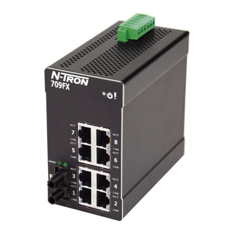
Ntron 709FX Series Installation and operating instructions

Ntron

Ntron 709FX Series Installation and operating instructions

Ntron 708 Series Owner's manual

Ntron

Ntron 708 Series Owner's manual

Ntron 7014 Series Quick start guide

Ntron

Ntron 7014 Series Quick start guide

Ntron 7026 Series Installation and operating instructions

Ntron

Ntron 7026 Series Installation and operating instructions

Ntron 608MFX-ST User manual

Ntron

Ntron 608MFX-ST User manual

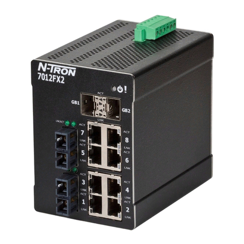
Ntron 7012FX2 Series Installation and operating instructions

Ntron

Ntron 7012FX2 Series Installation and operating instructions

Ntron 526FX2 User manual

Ntron

Ntron 526FX2 User manual

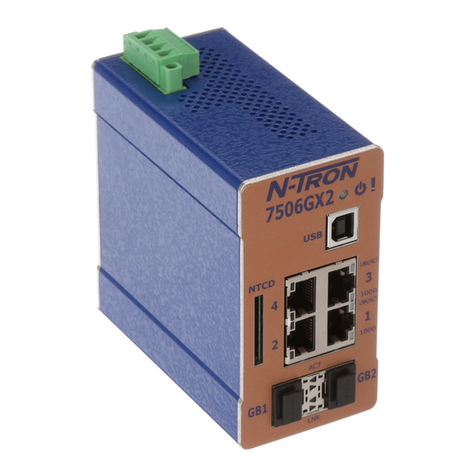
Ntron 7506GX2 Series Installation and operating instructions

Ntron

Ntron 7506GX2 Series Installation and operating instructions

Ntron 708TX Installation and operating instructions

Ntron

Ntron 708TX Installation and operating instructions

Ntron 105M12 User manual

Ntron

Ntron 105M12 User manual

Ntron 105FX-POE Installation and operating instructions

Ntron

Ntron 105FX-POE Installation and operating instructions

Ntron 9000 Series Installation and operating instructions

Ntron

Ntron 9000 Series Installation and operating instructions

Ntron 7014TX Installation and operating instructions

Ntron

Ntron 7014TX Installation and operating instructions

Ntron 308FX2 Installation and operating instructions

Ntron

Ntron 308FX2 Installation and operating instructions

Ntron 405FX-SC User manual

Ntron

Ntron 405FX-SC User manual

Ntron 100 Series Installation and operating instructions

Ntron

Ntron 100 Series Installation and operating instructions

Ntron 716M12 Installation and operating instructions

Ntron

Ntron 716M12 Installation and operating instructions

Popular Switch manuals by other brands

Transition Networks SISTP1040-382B-LRT install guide

Transition Networks

Transition Networks SISTP1040-382B-LRT install guide

Lantech IPES-5208T-X Series user manual

Lantech

Lantech IPES-5208T-X Series user manual

H3C S5800-EI Series installation guide

H3C

H3C S5800-EI Series installation guide

Wenglor ZAC5 EN0 Series operating instructions

Wenglor

Wenglor ZAC5 EN0 Series operating instructions

Aiphone AX-248C Specifications

Aiphone

Aiphone AX-248C Specifications

Avocent SwitchView IP 1020 Quick installation guide

Avocent

Avocent SwitchView IP 1020 Quick installation guide

Cisco M SFS7000E Installation note

Cisco

Cisco M SFS7000E Installation note

Extron electronics VSW 2VGA A Setup guide

Extron electronics

Extron electronics VSW 2VGA A Setup guide

Hirschmann MSM20 user manual

Hirschmann

Hirschmann MSM20 user manual

Citrix 9000 Series user guide

Citrix

Citrix 9000 Series user guide

HP StorageWorks 2/140 - Director Switch installation guide

HP

HP StorageWorks 2/140 - Director Switch installation guide

Southwire 40450 RVC troubleshooting guide

Southwire

Southwire 40450 RVC troubleshooting guide

WolfPack HDTV4K604x4 user manual

WolfPack

WolfPack HDTV4K604x4 user manual

TRENDnet TE-500 Specifications

TRENDnet

TRENDnet TE-500 Specifications

TRENDnet TPE-224WS - Web Smart PoE Switch Troubleshooting

TRENDnet

TRENDnet TPE-224WS - Web Smart PoE Switch Troubleshooting

PC Concepts USB 2.0 4-Port HUB TU2-400 user guide

PC Concepts

PC Concepts USB 2.0 4-Port HUB TU2-400 user guide

Grundfos IO 50 SQFlex Installation and operating instructions

Grundfos

Grundfos IO 50 SQFlex Installation and operating instructions

Kobold SCH-27 operating instructions

Kobold

Kobold SCH-27 operating instructions

manuals.online logo
manuals.online logoBrands
  • About & Mission
  • Contact us
  • Privacy Policy
  • Terms and Conditions

Copyright 2025 Manuals.Online. All Rights Reserved.