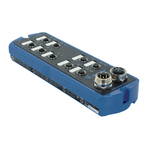
Wenglor ZAC5 EN0 Series User manual

Operating instructions
Available only as PDF
Status: 12.09.2016
www.wenglor.com
ZAC5xEN0x
Ethernet Switches
EN

2
EN
Index
1. Proper Use 4
2. Safety Precautions 4
3. Approvals and IP Protection 4
4. Technical Data 5
4.1. Connection table ZAC50EN0x 6
4.2. Connection table ZAC51EN01 7
4.3. Housing Dimensions 8
4.3.1 ZAC5xxN01 8
4.3.2 ZAC50xN02 8
4.4. Complementary Products 9
5. Application Notes 13
6. Mounting Instructions 13
7. Initial Operation 13
7.1. System Structure 14
7.2. Power Cable 14
7.3. Functional Earth 15
7.4. Industrial Ethernet Cable 15
7.5. Industrial Ethernet Cable with Power over Ethernet 16
7.6. Connecting Digital Sensors and Actuators 16
7.7. Diagnosis 17
7.7.1 LED Display EtherNet/IPTM Device (ZAC50EN0x) 17
7.7.2 LED Display EtherNet/IPTM Device (ZAC51PN01) 18
7.8. Operation using a controller without EDS file use 20
8. Detailed description of the modules for EtherNet/IPTM devices 21
8.1. Identity object (0x01) 21
8.2. Message router object (0x02) 22
8.3. Assembly object (0x04) 23
8.4. Connection manager object (0x06) 24
8.5. Discrete input point objects (0x08) 25
8.6. Discrete output point objects (0x09) 25
8.7. QoS object (0x48) 26
8.8. Port object (0xF4) 27
8.9. TCP/IP interface object (0xF5) 28
8.10. Ethernet link object (0xF6) 29

3
8.11. Vendor-specific object (0x64) 30
8.11.1 Configuration assembly for ZAC50EN01 and ZAC50EN02 30
8.11.2 Configuration assembly for ZAC51EN01 30
8.12. Connections 31
9. Web-based Configuration 31
9.1. Call up the Administration Interface 31
9.2. Overview page 34
9.3. Device settings 35
9.4. Industrial Ethernet Ports Settings 37
9.5. Digital I/O Ports Settings 38
10. Maintenance Instructions 39
11. Proper Disposal 39
12. EU Declaration of Conformity 39

4
EN
1. Proper Use
This wenglor product must be used in accordance with the following functional principle:
Switch
A Switch is an active network component which distributes data to the corresponding addressees within a
network in a targeted fashion. wenglor switches are fitted optionally with additional Power over Ethernet tech-
nology. The power supply is integrated into existing network connection by means of Power over Ethernet. As
an addition to Industrial Ethernet, there are several digital inputs and outputs directly on the switch that can be
activated or evaluated via the network.
2. Safety Precautions
• This operating instruction is part of the product and must be kept during its entire service life.
• Read this operating instruction carefully before using the product.
• Installation, start-up and maintenance of this product has only to be carried out by trained personnel.
• Tampering with or modifying the product is not permissible.
• Protect the product against contamination during start-up.
• Not a safety component in accordance with the EU Machinery Directive.
3. Approvals and IP Protection
IND. CONT. EQ.
E480617
RoHS

5
4. Technical Data
Order number ZAC50EN01 ZAC50EN02 ZAC51EN01
Supply voltage 18...32 V DC 18...32 V DC 18...32 V DC
Max. Current Consumption Device * 0.3 A 0.25 A 0.3 A
Max. Current Consumption System ** 2.2 A 2 A 0.3 A
max. PoE Capacity 30 W 25 W –
Temperature range –25...60 °C –25...60 °C –25...60 °C
Voltage drop switching outputs < 2.5 V < 2.5 V < 2.5 V
Max. Switching current switching
outputs 0.6 A 0.6 A 0.6 A
Max. total current of the
digital I/O ports 1A 1A 1A
Digital I/O ports short-circuit pro-
tected Yes Yes Yes
Digital I/O ports overload protected Yes Yes Yes
Digital I/O ports reverse polarity
protected Yes Yes Yes
Number of digital I/O ports 2 2 2
Housing material Aluminum Aluminum Aluminum
Protection class IP67 IP67 IP67
Type of connection power 7/8", 5-pin 7/8", 5-pin 7/8", 5-pin
Type of Connection Industrial
Ethernet Ports
M12×1, 4-pin,
D-coding
M12×1, 4-pin,
D-coding
M12×1, 4-pin,
D-coding
Type of Connection PoE Ports M12×1, 8-pin, type x M12×1, 8-pin, type x –
Type of Connection Digital I/O ports M12×1, 4-pin,
A-coding
M12×1, 4-pin,
A-coding
M12×1, 4-pin,
A-coding
Number of PoE ports 5 2 –
Number of Industrial Ethernet Ports 227
Number of Digital I/O ports 222
PoE Standard IEEE802.3af IEEE802.3af –
PoE Classes Class 0, 1, 2, 3 Class 0, 1, 2, 3 –
Baud Rate 10 Mbit/s / 100 Mbit/s 10 Mbit/s / 100 Mbit/s 10 Mbit/s / 100 Mbit/s
Transmission Mode Full / Half Duplex Full / Half Duplex Full / Half Duplex
Webserver Yes Yes Yes
Switch Mode Store & Forward Store & Forward Store & Forward
VLAN Prioritization Yes Yes Yes
Auto-Crossover Yes Yes Yes
Auto-Negotiating Yes Yes Yes
Auto-Polarity Yes Yes Yes
* Maximum own power consumption of the product without additional loads
** Maximum own power consumption of the product with additional loads
Full assignment of all PoE ports (if available) without digital I/O ports

6
EN
4.1. Connection table ZAC50EN0x
Function
Pin
1 TxD (+)
2 RxD (+)
3
4
Socket 2
In/
Out
TxD (−)
RxD (−)
Function
Pin
1
2 TxD (−)
3
4
5
6
7
8
Socket 1
In/
Out
PoE (+)
In
Out
In
Out
In
Suitable Plug:
Out
In
Out
Out
Out
Out
Out
Out
Out
TxD (+)
RxD (−)
RxD (+)
PoE (+)
PoE (−)
PoE (−)
www.wenglor.com
77
50
Suitable Plug: 51
Suitable Plug: 2
Suitable Plug: 7877
50
50
Socket 1
Socket 1
51
2
Socket 2
Socket 3
77
Socket 4
51
2
Socket 2
Socket 3
78
Socket 4
50
50
Socket 1
Socket 1
50
Socket 1
Function
Pin
1 +24 V DC
2 I/O
3
4
Socket 3
In/
Out
GND
I/O
Socket 4
5
Function
Pin
1 0 V DC
2 0 V DC
3
4+24 V DC USystem
5 +24 V DC UDigital I/O / Sensor
www.wenglor.com
52
50
Socket 1
51
Socket 2
2
Socket 3
78
Socket 4
50
Socket 1
51
Socket 2
2
Socket 3
77
Socket 4

7
4.2. Connection table ZAC51EN01
www.wenglor.com
Function
Pin
1 TxD (+)
2 RxD (+)
3
4
Socket 2
In/
Out
TxD (−)
RxD (−)
Out
In
Out
In
Socket 3 Suitable Plug:
77
Function
Pin
1 +24 V DC
2 I/O
3
4
Socket 1
GND
I/O
Suitable Plug:
5
FunctionPin
1 0 V DC
2 0 V DC
3
4+24 V DC USystem
5 +24 V DC UDigital I/O / Sensor
51
7877
Suitable Plug: 2
54
51
51
Socket 2
Socket 2
51
2
Socket 2
Socket 1
77
Socket 3
51
Socket 2
51
51
Socket 2
Socket 2
51
2
Socket 2
Socket 1
78
Socket 3

8
EN
4.3. Housing Dimensions
4.3.1 ZAC5xxN01
4.3.2 ZAC50xN02

9
4.4. Complementary Products
Connection plug, 7/8", 5-pin Order number: ZAT77NN01
Suitable Plug:
77
S82
Connection socket, 7/8", 5-pin Order number: ZAB78NN01
Suitable Plug:
78
Connecting cable, 7/8", 5-pin Order number: ZAV78R201, Cable length: 2 m
Suitable Plug:
78
S76
S87

10
EN
Connecting line, 7/8", 5-pin Order number: ZAS78R601, Cable length: 10 m
Suitable Plug:
78
S75
Connector Plug RJ45; 8-pin Order number: ZAT45NN01
Suitable Plug:
45
S48
Connection plug, M12×1; 8-pin Order number: ZAT50NN01
Suitable Plug:
50
S48

11
Connecting cable M12×1; 8-pin Order number: ZAV50R201, Cable length: 2 m
Order number: ZAV50R501, Cable length: 5 m
Suitable Plug:
50
S81
Order number: ZAV50R502, Cable length: 5 m
Suitable Plug:
50
S85
Connecting line M12×1, 8-pin Order number: ZAS50R601, Cable length: 10 m
Suitable Plug:
50
S85
Connection plug, M12×1, 4-pin Order number: ZAT51NN01
Suitable Plug:
51
S08

12
EN
Connecting cable M12×1; 4-pin; D-coding Order number: ZAV51R201, Cable length: 2 m
Order number: ZAV51R601, Cable length: 10 m
Suitable Plug:
51
Order number: ZAV51R202, Cable length: 2 m
Order number. ZAV51R602, Cable length: 10 m
Suitable Plug:
51
2
Connection and power supply cables
M12×1; 4-pin, different lengths are available for connecting the Sensor/actuator.
Legend
Wire Colors according to
DIN IEC 757
Platinum measuring resistor
not connected
Test Input
Test Input inverted
Trigger Input
Analog Output
Ground for the Analog Output
Block Discharge
Valve Output
Valve Control Output +
Valve Control Output 0 V
Synchronization
Receiver-Line
Emitter-Line
Grounding
Switching Distance Reduction
Ethernet Receive Path
Ethernet Send Path
Interfaces-Bus A(+)/B(–)
Emitted Light disengageable
Magnet activation
Input confirmation
Contactor Monitoring
Encoder A/A (TTL)
Encoder B/B (TTL)
Black
Brown
Red
Orange
Yellow
Green
Blue
Violet
Grey
White
Pink
Green/Yellow
Supply Voltage +
Supply Voltage 0 V
Supply Voltage (AC Voltage)
Switching Output (NO)
Switching Output (NC)
Contamination/Error Output (NO)
Contamination/Error Output (NC)
Input (analog or digital)
Teach Input
Time Delay (activation)
Shielding
Interface Receive Path
Interface Send Path
Ready
Ground
Clock
Output/Input programmable
Power over Ethernet
Safety Input
Safety Output
Signal Output
Ethernet Gigabit bidirect. data line (A-D)
Encoder 0-pulse 0-0 (TTL)
Encoder A
Encoder B
Digital output MIN
Digital output MAX
Digital output OK
Synchronization In
Synchronization OUT
Brightness output
Maintenance
PT

13
5. Application Notes
The Ethernet ports are fitted with overvoltage discharge protection. Internal varistors limit voltage surges to
approx 70 V. The connecting cables of the digital I/O ports must not be longer than 30 m.
6. Mounting Instructions
When mounting and operating the switches, the corresponding electrical and mechanical regulations, stan-
dards and safety rules must be observed. The switch must be protected against mechanical influences. The
product must be fastened in such a way that the mounting position cannot change. The switch is designed for
use in the industrial sector. The industrial environment is characterized in that consumers are not connected
directly to the public low-voltage mains network. Additional measures must be taken for use in the residential
sector, business and commercial sectors.
The table below defines the tightening torques of the plugs and fastening options for ensuring compliant and
faultless operation.
Connection type Tightening torque in (Nm)
M12 0.4
7/8" plug 1.5
FE ground strap 2.2±0.2
Switch Mounting 4.0±0.2
7. Initial Operation
Project planning, installation, start-up, maintenance and testing of the devices may only be carried out by quali-
fied electrical technicians familiar with the safety standards of automation technology.
Only cables and accessories that meet the standards and requirements for safety, electromagnetic compat-
ibility and, if necessary, telecommunications terminal equipment and the specifications. In case of damage, the
product must not be used further on. In the event of improper use, the guarantee and liability claim against the
manufacturer shall lapse.
Information concerning which cables and accessories are approved for installation can be found at
www.wenglor.com or are described in this manual.

14
EN
7.1. System Structure
7.2. Power Cable
1
2
34
5
1
2
3
4
5
Power In Power Out
0 V Pin 1 0 V Pin 1
0 V Pin 2 0 V Pin 2
Pin 3 FE Pin 3
24 V max. 9 A Pin 4 USystem 24 V max. 9 A Pin 4
24 V max. 9 A Pin 5 UDigital I/O / Sensor 24 V max. 9 A Pin 5
The 7/8" plug is designed for a maximum current of 9 A per pin. This must be taken into account when looping
the supply voltage.
The switch must be connected to a power supply of 18 to 32 V DC. The USystem/Sensor supplies the connection
with voltage and the UDigital I/O provides the power supply of the digital I/O ports.
The voltage of the USystem must not be switched off during ongoing operation and hence must not be con-
ducted via emergency stop circuits, since otherwise the switch and all connected Ethernet products will not be
able to participate in the communication.
Digital
I/O-Ports
Digital
I/O-Port
Industrial Ethernet
Power

15
Measures must be taken in all cases to ensure that the supply voltage, measured at the remotest partici-
pant, does not fall short of the system supply voltage of 18 V DC.
To be complied with in reactive operation:
If the power supply of the digital I/O ports is merged with the voltage supply of the switch, there will then
be the risk of a communication disruption in the event of a short-circuit on the I/O devices.
7.3. Functional Earth
The FE connection is on the lower front edge of the switch. To ensure proper functioning in accordance with
the EMC regulations specified in the data sheet, we recommend using our ground strap, which is included in
the scope of delivery (for tightening torque see “Mounting Instructions” on page 13).
7.4. Industrial Ethernet Cable
wenglor provides a variety of preassembled industrial Ethernet cables.
To ensure cabling as simple and reliable as possible, we recommend using our preassembled Industrial
Ethernet cables.
Assignment of the Industrial Ethernet connection:
1
2
3
4
Pin Function
1 TxD (+)
2 RxD (+)
3 TxD (–)
4 RxD (–)

16
EN
7.5. Industrial Ethernet Cable with Power over Ethernet
To ensure cabling as simple and reliable as possible, we recommend using our preassembled industrial Eth-
ernet cables. It is also possible to interconnect two switches with PoE via the 8-pin network cable. The PoE
supply should then be switched off on at least one of the two PoE ports (see “Industrial Ethernet Ports Settings”
on page 37).
Assignment of the Industrial Ethernet connection with PoE:
1
2
3
45
6
8
7
Pin Function
1 TxD (+)
2 TxD (–)
3 RxD (+)
4RxD(–)
5 PoE (+)
6 PoE (+)
7 PoE (–)
8 PoE (–)
7.6. Connecting Digital Sensors and Actuators
1 2
34
Pin Function
1 24 V
2Freely programmable
input/output
3 0 V
4Freely programmable
input/output
Sockets that are not used must be provided with caps, which are included in the scope of supply. Otherwise,
the protection class IP67 cannot be guaranteed.

17
7.7. Diagnosis
Assignment example:
Net
1
3 4
5
2
A B
X0 X1
Mod PoE max
PoE
L/A
PoE
L/A
PoE
L/A
PoE
L/A
PoE
L/A
IO
0.0
Power
24 V In
IO
1.0
IO
0.1
IO
1.1
L/A L/A
24 V Out
Net
1 2
A B
X0 X1
Mod PoE max
PoE
L/A
PoE
L/A
IO
0.0
Power
IO
1.0
IO
0.1
IO
1.1
L/A L/A
24 V In 24 V Out
Net
3
5 6
7
4
1 2
X0 X1
Mod
L/A
L/A L/A
L/A
L/A
IO
0.0
Power
24 V In
IO
1.0
IO
0.1
IO
1.1
L/A L/A
24 V Out
ZAC50EN01 ZAC50EN02 ZAC51EN01
7.7.1 LED Display EtherNet/IPTM Device (ZAC50EN0x)
The status displays for the communication are marked on the switch with CS and MS.
Designation Condition Function
Net
Off No IP address
Green CIP connection established
Green flashing IP address assigned, no CIP connection
Red IP address assigned twice
Red flashing CIP connection interrupted
Mod
Green Ready for operation
Green flashing Standby
Red Permanent error
Red flashing Temporary error
PoE max Red Maximum PoE performance reached
Red flashing PoE performance monitoring was switched off

18
EN
The LED display on the M12 sockets displays the diagnosis for the corresponding socket.
2PoE
L/A
Designation Condition Function
PoE Yellow PoE in operation
Yellow flashing PoE function switched off
L/A Green Link exists
Green flashing Communication
X0 IO
0.0
IO
1.0
Designation Condition Function
IO 0.0/IO 1.0 Yellow Input UB at Pin 2/4
Output Switching output at UB Pin 2/4
Red Output Short circuit at Pin 2/4
7.7.2 LED Display EtherNet/IPTM Device (ZAC51PN01)
The status displays for the communication are marked on the switch with CS and MS.
Designation Condition Function
Net
Off No IP address
Green CIP connection established
Green flashing IP address assigned, no CIP connection
Red IP address assigned twice
Red flashing CIP connection interrupted
Mod
Green Ready for operation
Green flashing Standby
Red Permanent error
Red flashing Temporary error
The LED display on the M12 sockets displays the diagnosis for the corresponding socket.

19
1
L/A
Designation Condition Function
L/A Green Link exists
Green flashing Communication via port
X0 IO
0.0
IO
1.0
Designation Condition Function
IO 0.0/IO 1.0 Yellow Input UB at Pin 2/4
Output Switching output at UB Pin 2/4
Red Output Short circuit at Pin 2/4

20
EN
7.8. Operation using a controller without EDS file use
If you wish to start up the device on a controller, please carry out the following steps:
• Attach the switch to the supply voltage and connect this to the controller via one of the Ethernet ports.
You can find the appropriate connection technology on the wenglor homepage.
• Create a new project in the controller
• Add a new module to this project
• When selecting the communication module „General Ethernet module“ should be used
• The properties of the new module should match the connection parameters of the relevant product. In the
example of the switch the communication format selected should be „Data SINT“. To be able to access the
switch in the network an IP address should be assigned in addition. In delivery condition this is requested
by the product via a DHCP server.
• Creating the Config Assembly (not mandatory). Default Config = I/O ports to input, active performance
monitoring, all ports are released for PoE
• After the program has been created, connect to the controller and load program
For a detailed description for different controllers and for installation of the files or project planning of the net-
work refer to the help files of the relevant controller. wenglor provides a short exemplary instruction for commis-
sioning of an EtherNet/IPTM device (www.wenglor.com Product World Product search (order number)
Download General instructions).
This manual suits for next models
3
Table of contents
Other Wenglor Switch manuals
Popular Switch manuals by other brands

Lantech
Lantech IGS-2404 user manual

Siemens
Siemens SENTRON 3KC0 manual

Trust
Trust SMART Home START-LINE RECEIVER AWMR-300 Important information

HP
HP StorageWorks 2/64 - Core Switch installation guide

Siemens
Siemens DELTA 5TC1 233 Operating and mounting instructions

OTS
OTS ET4222Pp9H-S-DR Quick installation guide