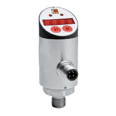
Kobold SCH-27 User manual

Operating Instructions
for
Pressure Switch
Model: SCH-27/SCH-28

SCH-27/-28
page 2 SCH-27/-28 K04/0722
We don’t accept warranty and liability claims neither upon this publication nor in
case of improper treatment of the described products.
The document may contain technical inaccuracies and typographical errors. The
content will be revised on a regular basis. These changes will be implemented in
later versions. The described products can be improved and changed at any time
without prior notice.
© Copyright
All rights reserved.

SCH-27/-28
SCH-27/-28 K04/0722 page 3
1. Contents
1. Contents .......................................................................................................3
2. Note..............................................................................................................4
3. Instrument Inspection....................................................................................4
4. Regulation Use .............................................................................................5
5. Mechanical Connection.................................................................................5
5.1 Important Information...........................................................................5
5.2 Installation ...........................................................................................7
6. Electrical Connection....................................................................................8
6.1 Set Point Calibration............................................................................9
7. Commissioning ...........................................................................................10
8. Working Limits ............................................................................................11
8.1 Working temperature.........................................................................11
8.2 Working pressure ..............................................................................11
8.3 Cyclic and dynamic pressures...........................................................11
8.4 Overpressure.....................................................................................11
8.5 Vibrations...........................................................................................11
8.6 Micro-switch.......................................................................................11
8.7 Differential .........................................................................................12
8.8 Protection degree..............................................................................12
8.9 Corrosive fluids and gas liquids.........................................................12
9. Improper usage...........................................................................................12
9.1 Failure for fatigue...............................................................................12
9.2 Failure for overpressure.....................................................................13
9.3 Failure for corrosion...........................................................................13
9.4 Failure for explosion ..........................................................................13
9.5 Failure for vibrations..........................................................................13
9.6 Stress for vibrations...........................................................................13
9.7 Mechanical stress..............................................................................14
10. Maintenance...............................................................................................14
10.1 Regular check....................................................................................14
10.2 Recalibration......................................................................................14
11. Technical Information..................................................................................15
12. Order codes................................................................................................17
13. Dimensions.................................................................................................19
14. Disposal......................................................................................................23
15. EU Declaration of Conformance .................................................................24
Manufactured and sold by:
Kobold Messring GmbH
Nordring 22-24
D-65719 Hofheim
Tel.: +49(0)6192-2990
Fax: +49(0)6192-23398
E-Mail: info.de@kobold.com
Internet: www.kobold.com

SCH-27/-28
page 4 SCH-27/-28 K04/0722
2. Note
Please read these operating instructions before unpacking and putting the unit
into operation. Follow the instructions precisely as described herein.
The instruction manuals on our website www.kobold.com are always for currently
manufactured version of our products. Due to technical changes, the instruction
manuals available online may not always correspond to the product version you
have purchased. If you need an instruction manual that corresponds to the
purchased product version, you can request it from us free of charge by email
(info.de@kobold.com) in PDF format, specifying the relevant invoice number and
serial number. If you wish, the operating instructions can also be sent to you by
post in paper form against an applicable postage fee.
The devices are only to be used, maintained and serviced by persons familiar
with these operating instructions and in accordance with local regulations
applying to Health & Safety and prevention of accidents.
When used in machines, the measuring unit should be used only when the
machines fulfil the EC-machine guidelines.
as per PED 2014/68/EU
PS ≤ 200 bar
In acc. with Article 4 Paragraph (3), "Sound Engineering Practice", of the PED
2014/68/EU no CE mark.
PS > 200 bar
Category 1, module A
3. Instrument Inspection
Instruments are inspected before shipping and sent out in perfect condition.
Should damage to a device be visible, we recommend a thorough inspection of
the delivery packaging. In case of damage, please inform your parcel service /
forwarding agent immediately, since they are responsible for damages during
transit.
Scope of delivery:
The standard delivery includes:
•Pressure Switches model: SCH-27 or SCH-28

SCH-27/-28
SCH-27/-28 K04/0722 page 5
4. Regulation Use
Any use of the Pressure Switch, model: SCH-27 or SCH-28, which exceeds the
manufacturer’s specification, may invalidate its warranty. Therefore, any resulting
damage is not the responsibility of the manufacturer. The user assumes all risk
for such usage.
5. Mechanical Connection
5.1 Important Information
The instrument described in this manual has been designed and produced in
conformity to the following standards in force. All components are submitted to
severe quality and traceability controls. The quality management system is
certified according to the ISO 9001 standard. This manual contains important
information about the use and the installation of the gauge in safe conditions.
Therefore, it is highly recommended to read carefully the following instructions
before using the instrument.
The instrument works in safe conditions when correctly selected and installed in
the system and when the rules concerning the product as well
as the maintenance procedures established by the manufacturer are respected.
The staff charged with the selection, installation and maintenance of the
instrument must be able to recognize the conditions that may
negatively affect the instrument's ability to work and which may lead to premature
breakage. The staff must therefore be technically qualified
and properly trained, and must carry out the procedures called for in the plant
regulations.
Warning!
-The manufacturer disclaims all responsibility in case of damages
caused by the improper use of the product and by the non-respect
of the instructions reported in this manual.
-Follow carefully the specific safety rules an case of measuring
oxygen pressure, acetylene, inflammable or toxic gas or liquids.
-Disconnect the instruments only after depresurrization of the
system.
-The process fluids residuals in the disassembled instruments
could affect people, the environment and the system. It is highly
recommended to take proper precautions.

SCH-27/-28
page 6 SCH-27/-28 K04/0722
Attention!
-Before installation be sure that the right instrument has been
selected following the working conditions and in particular range,
the working temperature and the compatibility between the
material used and the process fluid.
-This manual does not concern the instruments conforming to
standard 2014/34/EU (ATEX).
-The product warranty is no longer valid in case of non-
authorized modifications and of wrong use of the product.
-The user is totally responsible for the instrument installation and
maintenance.

SCH-27/-28
SCH-27/-28 K04/0722 page 7
5.2 Installation
Fix the instrument thread forcing by a key which should fit with the process
connection without forcing by hand on the case. As for the cylindric thread
process connection is concerned (Gas or metric) a head gasket compatible with
the fluid or gas to measure should be used. (Fig.1).
In case of conic connection thread (NTP or Conic gas), a PTFE tape on the male
thread (Fig.2) ensures the sealing before proceeding to screw and then to the
fixing.
In case of conic connection thread (NTP or Conic gas), a PTFE tape on the male
thread (Fig.2) ensures the sealing before proceeding to screw and then to the
fixing.
In both cases it is necessary to fix the instrument through two keys: one on the
flat sides of the instrument process connection, the other one on the pressure
output. All instruments should be mounted in a vertical position unless otherwise
shown on the label.
In order to make the instrument dismounting easier it is recommended to mount a
shut-off valve between the system and the instrument.

SCH-27/-28
page 8 SCH-27/-28 K04/0722
6. Electrical Connection
Pressure switches type: SCH-27 are equipped with micro-switch suitable for
direct connection through fork wire terminal screws and clamp for ground
connection both internal and external provided of cable terminal.
Differential pressure switches model SCH-28 are provided of internal terminal
blocks with screws terminals (Figure 5) with cables whose maximum section
should be di 2.5 mm² and terminal block for ground connection both internal and
external provided of wire terminal. In order to perform the electrical connection,
proceed to unplug the pressure switch case top. For connection, use cables
whose section is adequate to the requested electrical charge (1.2...2.5 mm2 -
14...16 AWG) in conformity to the technical requirements concerning connection
and commutation instruments. The cable diameter should be suitable for passing
through cable glands.
Wiring:
- do not torch or pull the cable excessively;
- cables should not be frayed and the isolating sheath should not be cut or
damaged;
- false contacts should be prevented and the terminal screws should be properly
tightened;
- calibration should not be modified (factory calibration).
No residue should remain inside the case and the top should be fastened by a
lock nut.

SCH-27/-28
SCH-27/-28 K04/0722 page 9
6.1 Set Point Calibration
If not otherwise specified in the order the instrument is supplied with a set point
calibrated on the lowest possible value. Calibration must be performed fixing the
pressure switch and a laboratory instrument for the pressure measuring in
parallel to a pressure output. And (Fig. 6). For calibration, please proceed as
follows:
Instrument provided of 1 micro-switch
1. Connect the micro-switch to warning lamp or a sound source as shown in fig.5
in order to be warned if any malfunction should occur during operation;
2. apply a pressure or a vacuum whose value should be the same as the value of
operation;
3. when the proper operation pressure value is reached and no warning signal
hasn’t been detected, it is necessary to rotate the microswitch adjustment screw
until the successful operation signal is on;
4. conversely, if the operation signal is shown before reaching the expected
pressure value, rotate the adjustment screw clockwise until the operational
signal is off.
5. proceed by producing several pressure ups and downs in order to verify the
set point accuracy as described in points 8 and 9.
Instrument provided of 2 micro-switches
The calibration procedure is the same as described for instruments provided with
1 microswitch considering that these operations should be repeated for one
micro-switch at a time alternatively until the desired operation accuracy is
reached. This is necessary because the two micro-switches interaction on the
same measuring instrument.

SCH-27/-28
page 10 SCH-27/-28 K04/0722
7. Commissioning
Commissioning should always be performed carefully in order to prevent any
shock or sudden temperature variations. Slowly open the shut-off valves placed
between the instrument and the process.
As for differential pressure switches model SCH-28, please refer to figure 7 and
follow the following instructions:
1. open the by-pass valve “1”;
2. open the root valve “3”;
3. open the shut-off valve “2” of the positive side (+);
4. shut the by-pass valve “1”;
5. open the shut-off valve “2” of the negative side (-).
All obstruction of the sensing element pressure abduction pipe should be avoided
in order to prevent any repeated and unnecessary rearm of the micro-switch. In
case of malfunction, the instrument must be completely depressurized and
isolated through a shut-off valve before removal.
Figure 7

SCH-27/-28
SCH-27/-28 K04/0722 page 11
8. Working Limits
8.1 Working temperature
This instrument is designed to be used safely in an ambient temperature between
–20 and +65°C
8.2 Working pressure
The instrument should be selected among those having an adjustment range
which should be approximately the double of working pressure value that could
be between 25% and 75% of the pressure switch range. As for ranges < 1bar any
accidental vacuum higher than the working range of the instrument should be
prevented.
8.3 Cyclic and dynamic pressures
They generally appear when the instruments are mounted on pumps bringing to a
relevant reduction of the sensing element and the microswitch life. They might
cause uninterrupted false alarms. It is necessary to decrease these pulsations
placing a shut-off valve between the pressure source and the instrument. If the
instrument is selected inaccurately, a fatigue breakage could occur.
8.4 Overpressure
Overpressure may affect the sensing element decreasing its life and accuracy.
Therefore, an instrument performing a full-scale range is wider than the maximum
working pressure is highly recommended since it is more likely to absorb
overpressure. Shocks could be treated just like the pulsating pressures. Long-
lasting overpressure can be prevented by installing a shut-off valve calibrated on
site. Even only one overpressure episode could permanently damage the
instrument.
8.5 Vibrations
When the instrument support receives vibrations, instruments must be mounted
far from vibrations and connected through capillaries (in case of strong and
irregular vibrations). If this is not possible, the instrument should be installed at
right angle position to the vibrations plan. Vibrations can be detected when the
micro-switch malfunctions permanently.
8.6 Micro-switch
A resistive charge which might be higher than that indicated on the instrument
label should not be applied. If this occurs, the case surface and the sheath
temperature could increase making the installation unsafe. According to the
micro-switch model, it is necessary to consider the differential value between the
working pressure and the restored one.

SCH-27/-28
page 12 SCH-27/-28 K04/0722
8.7 Differential
The difference between the working pressure value and that of the micro-switch
rearm is called differential or dead-band value and it appears on the instrument
label. The set point and the differential value should allow the micro-switch to
rearm correctly. This is an essential aspect for the micro-switch provided with an
adjustable differential range from 10% to 50% of the full working scale.
The differential value can be adjusted by turning on the graduated wheel located
under the micro-switch. The roller is graduated from letter A to letter F which
represents the minimum differential (around 10% of the adjustment range) and
maximum differential (about 40-50% of the adjustment range) respectively. While
adjusting the differential, be aware that the device increases the set working
pressure value leaving the rearm untouched, acting on the micro-switch click
force. It is important to remember, that when the instrument is provided with a
micro-switch, this is calibrated at the factory and then adjusted on site. This has
to be taken into account too, when the instrument works in vacuum.
8.8 Protection degree
According to EN 60529 regulation. It concerns the instrument’s top when this is
completely tightened. A special nut lock mounted on the case body should be
tightened to the top preventing its removal during normal operation conditions.
8.9 Corrosive fluids and gas liquids
The sensing element thickness is generally moderate so it can work in severe
mechanical stress conditions. The chemical compatibility with the fluid to
measure has to be considered. No common material can be immune from a
chemical attack whose intensity can be influenced by the following conditions:
concentration, temperature and the mixture type among different chemical
substances. A chemical attack can lead rapidly to a corrosion failure.
9. Improper usage
9.1 Failure for fatigue
Pressure may produce a mechanical stress which could damage the sensitive
element permanently since it might crack. The crack can be more dangerous if it
happens during compressed and liquid gas measuring because the sensing
element leaks slowly so that the pressure inside the case increases and the
safety gasket opens.

SCH-27/-28
SCH-27/-28 K04/0722 page 13
9.2 Failure for overpressure
It occurs when a higher pressure than the declared one for the sensing element is
applied (i.e. when an instrument for low pressures is installed on a system
working with high pressure). The effects of this kind of damage, which are
commonly more serious in case of compressed gas measuring, are not
predictable and may lead to the case explosion despite the safety gasket. Spikes
may happen in hydraulic and pneumatic systems especially after the opening and
the closing of valves.
Spikes amplitude may be much higher than the working pressure. They cannot
be detected by the instrument because of their quickness therefore they are not
detectable by the operator. Spikes may affect the instrument permanently. A
choke may reduce the overpressure amplitude pike transmitted to the sensing
element. A shut-off valve could protect the instrument from pressures higher than
pressures the instrument is calibrated for.
9.3 Failure for corrosion
When the sensing element material is attacked by the process fluid chemical
substances or by other substances that may be present in the pressure system, a
leakage or a stress crack may occur. In this case it is advisable to install a
diaphragm compatible with the process fluid or a fluid diaphragm seal.
9.4 Failure for explosion
A powerful release of thermal energy due to chemical reactions such as the
oxygen adiabatic compression reaction in presence of hydrocarbons might
produce an explosion. The inability to force this kind of damage is generally
accepted. It is advisable to clean and de-grease the wetted parts with special
products in case the instrument has to be interchanged in order to prevent any
chemical reaction in the system. In case of use of highly oxidant agents (e.g.
oxygen) the producer should be informed during order procedure.
9.5 Failure for vibrations
The movable components of the instrument can be damaged by vibrations even if
they are not too severe. First the accuracy of operation decreases then damages
may occur involving the general functioning of the instrument. In order to prevent
vibrations damage the instrument should be mounted far from vibrations and
connected to the system through a capillary.
9.6 Stress for vibrations
Wide amplitude vibrations could also break the sensing element structure and
lead to a process fluid leakage.

SCH-27/-28
page 14 SCH-27/-28 K04/0722
9.7 Mechanical stress
Instruments should not receive any mechanical stress. If the installation points
are under mechanical stress, the instruments should be mounted far from
vibrations and connected to the system through a capillary.
Instruments must be selected among those provided with wall or panel
anchorage.
10.Maintenance
The instrument’s characteristics should be maintained during time in order to
prevent damages caused by high temperatures, fire risk and explosion due to
possible malfunctions during operation.
As for heavy work instruments operating in severe conditions plants (vibrations,
pulsating pressures, corrosive or sedimentous fluids, fuel or inflammable fluids)
we recommend to schedule their replacement according to the maintenance
program schedule. In case the instrument does not work properly it is necessary
to proceed to an unscheduled checking procedure.
10.1 Regular check
In order to verify the sensing element conditions, it is advisable to install the
instrument on the pressure generator adding a shut-off valve between them.
Apply the maximum pressure value to the gauge and isolate it form the pressure
source through the valve. Any possible leakage of the sensing element can be
noticed from the slow restore of the pointer to zero.
10.2 Recalibration
If recalibration results are different from the nominal values declared on the
recalibration procedure should be repeated. The return of the instrument to
KOBOLD is recommended for this procedure.
The verification the switch point must be performed in accordance with the
operating conditions of the instruments and in particular in accordance with the
switching frequency.
Just as an example, control interval of six months is suggested in case of
marginal number of switches per day. In case of higher switching frequencies, the
control interval should be reduced. The interval for the next verification of the
instrument’s switch point may be defined on the basis of the outcome of previous
verifications. In case of positive outcomes, the control interval can be increased.
In case of negative results, it should be decreased.
KOBOLD will not be responsible for any non authorized intervention on the
instrument. Moreover, the contract warranty and the CE Conformity
Declaration will be no longer valid.

SCH-27/-28
SCH-27/-28 K04/0722 page 15
11.Technical Information
Electrical specifications: 1... 2 SPDT microswitches
(see microswitches table)
Differential (dead band): Fixed (value as per setting range table),
adjustable (microswitch code E/F) from 10%
... 50% of setting range
Repeatability: ≤ 1% of the full setting value
Set-point adjustment: Internal, micrometric adjustable
Protection: IP 65 as per IEC 529
Electrical wiring: Terminal strip
Earth contact: 1 x internal and 1 x external
Process temperature: 100 °C max. (+212 °F)
Ambient temperature: -25 ... +65 ° C (-13 ... +149 °F)
Thermal drift: ≤ 0.05% / °C (≤ 0.027% / °F)
Process connection: AISI 316 stainless steel
Elastic element: AISI 316 stainless steel diaphragm
AISI 321 stainless steel bellows (SCH-28)
Gasket: PTFE
Flushing plugs: AISI 316 stainless steel
Case: AISI 304 stainless steel
Cover: AISI 304 stainless steel, bayonet lock
Tag: AISI 304 stainless steel, etched

SCH-27/-28
page 16 SCH-27/-28 K04/0722
Setting ranges SCH-27
Code
Setting range
Test
pressure
Special
overrange
(code H)
Differential
1 micro2)
Differential
2 micro2)
F7
0.7...6 mbar1)
10 mbar
0.5 mbar
F8
1...16 mbar1)
20 mbar
0.8 mbar
F9
2...25 mbar1)
30 mbar
1.2 mbar
F0
5...40 mbar1)
0.5 bar
400 mbar
4 mbar
5 mbar
F1
5...60 mbar1)
0.5 bar
600 mbar
4 mbar
5 mbar
F2
6...100 mbar1)
0.5 bar
1 bar
4 mbar
6 mbar
F3
9...160 mbar1)
0.5 bar
1.6 bar
6 mbar
9 mbar
F4
9...250 mbar1)
1 bar
2.5 bar
6 mbar
9 mbar
F5
15...400 mbar1)
1 bar
4 bar
10 mbar
15 mbar
F6
18...600 mbar1)
1 bar
6 bar
12 mbar
18 mbar
B2
0.06...1 bar1)
1.2 bar
10 bar
25 mbar
60 mbar
B3
0.06...1.6 bar1)
2 bar
16 bar
30 mbar
60 mbar
B4
0.06...2.5 bar1)
3 bar
25 bar
40 mbar
60 mbar
B5
0.08...4 bar
5 bar
40 bar
50 mbar
80 mbar
B6
0.09...6 bar
8 bar
40 bar
60 mbar
90 mbar
B7
0.15...10 bar
12 bar
40 bar
100 mbar
150 mbar
B8
0.25...16 bar
20 bar
40 bar
160 mbar
250 mbar
B9
0.4...25 bar
30 bar
40 bar
250 mbar
400 mbar
B0
0.6...40 bar
48 bar
60 bar
400 mbar
600 mbar
C1
0.9...60 bar
70 bar
80 bar
600 mbar
900 mbar
C2
6...100 bar
120 bar
4 bar
6 bar
C3
8...160 bar
185 bar
5 bar
8 bar
YY
Vacuum and compound range/consult factory
1) also available for vacuum and compound
2) differential and minimum set-point values for microswitches cod. I, L, N, R, S, T, U, V are 300%
of those shown in table
Setting ranges SCH-28
Code
Setting range
One side
static
pressure
Both side
static
pressure
Differential
1 micro1)
Differential
2 micro1)
B2
0.1...1 bar
10 bar
25 bar
60 mbar
80 mbar
B4
0.1...2.5 bar
15 bar
25 bar
60 mbar
80 mbar
B5
0.2...4 bar
15 bar
25 bar
70 mbar
100 mbar
B6
0.2...6 bar
15 bar
25 bar
100 mbar
150 mbar
B7
0.2...10 bar
15 bar
25 bar
120 mbar
170 mbar
1) differential and minimum set-point values for microswitches cod. I, L, N, R, S, T U, V are 300%
of those shown in table

SCH-27/-28
SCH-27/-28 K04/0722 page 17
12.Order codes
Order Details SCH-27 (Example: SCH-27 C2 A I2 1 N)
Model
Setting range
Microswitch type
Process
connection (F)
Electrical
connection (F1)
Options
SCH-27...
…F7…= 0.7...6 mbar1)
…A = standard,
single
…B = standard,
double
…I2) = goldplated,
single
…L2)= goldplated,
double
…M2)= inert gas
filled,
single
…P2)= inert gas
Filled,
double
…N2)= goldplated
and inert
gas filled,
single
…R2)= goldplated
and inert
gas filled,
double
…E3)= adjustable
differential,
single
…F3)= adjustable
differential,
double
...U2)= inert gas
filled VDC,
single
...V2)= inert gas
filled VDC,
double
I2 = ¼ -18 NPT F
N4 = ½ -14 NPT
F
I4 = ½ -14 NPT F
G4 = G ½ A
1 = R ½ -ISO 7/1
2= R ¾ -ISO 7/1
3 = ½ -14 NPT
4 = ¾ -14 NPT
A= M 20 x 1,5
N= none
H= special
over
pressure
stop
P= PTFE
covered
diaphragm
M= 2” stake’s
mounting
bracket
W= wall
mounting
bracket
T= tropicali-
sation
S= oxygen
service
Y= special
(specify in
clear text)
…F8…= 1...16 mbar1)
…F9…= 2...25 mbar1)
…F0…= 5...40 mbar1)
…F1…= 5...60 mbar1)
…F2…= 6...100 mbar1)
…F3…= 9...160 mbar1)
…F4…= 9...250 mbar1)
…F5…= 15...400 mbar1)
…F6…= 18...600 mbar1)
…B2…= 0.06...1 bar1)
...B3...= 0.06...1.6 bar1)
...B4...= 0.06...2.5 bar1)
...B5...= 0.08...4 bar
...B6...= 0.09...6 bar
...B7...= 0.15...10 bar
...B8...= 0.25...16 bar
...B9...= 0.4...25 bar
...B0...=0.6...40 bar
...C1...= 0.9...60 bar
...C2...= 6...100 bar
...C3...= 8...160 bar
...YY...= Vacuum and
compound
ranges(consult factory
1) also available for vacuum and compound
2) for pressure ranges ≥40 mbar
3) for pressure ranges ≥1 bar
Set-point Adjustment Microswitch Electrical Rating
Ohmic load
1)for
pressure ranges ≥40 mbar 2)for pressure ranges ≥1 bar
Single
Double
Type
250
VAC
125 V
AC
24 V
DC
A
B
standard
15 A
15 A
0.1 A
I
L
goldplated1)
1 A
0.1 A
M
P
inert gas filled1)
15 A
15 A
0.1 A
N
R
goldplated and
inert gas filled
1)
1 A
0.1 A
E
F
adjustable
differential
2)
20 A
20 A
0.1 A
U
V
inert gas filled VDC1)
15 A
15 A
6 A

SCH-27/-28
page 18 SCH-27/-28 K04/0722
Order Details SCH-28 (Example: SCH-28 B2 A I2 1 B)
Set-point Adjustment Microswitch Electrical Rating
Ohmic load
Model
Range
Microswitch type
Process
connection (F)
Electrical
connection (F1)
Options
SCH-28...
…B2…= 0.01...1 bar
...B4...= 0.1...2.5 bar
...B5...= 0.2...4 bar
...B6...= 0.2...6 bar
...B7...= 0.2...10 bar
…A = standard,
single
…B = standard,
double
…I = goldplated,
single
…L = goldplated,
double
…M = inert gas
filled,
single
…P = inert gas
Filled,
double
…N = goldplated
and inert
gas filled,
single
…R = goldplated
and inert
gas filled,
double
…E = adjustable
differential,
single
…F = adjustable
differential,
double
...U = inert gas
filled VDC,
single
...V = inert gas
filled VDC,
double
I2 = ¼ -18 NPT F
N4 = ½ -14 NPT
F
I4 = ½ -14 NPT F
G4 = G ½ A
1 = R ½ -ISO 7/1
2 = R ¾ -ISO 7/1
3= ½ -14 NPT
4= ¾ -14 NPT
A = M 20 x 1,5
N = none
B = bottom
connection
S = degreasing
for oxygen
M= 2” stake’s
mounting
bracket
W = wall
mounting
bracket
T= tropicali-
sation
Y= special
(specify in
clear text)
Single
Double
Type
250
VAC
125 V
AC
24 V
DC
A
B
standard
15 A
15 A
0.1 A
I
L
goldplated
1 A
0.1 A
M
P
inert gas filled
15 A
15 A
0.1 A
N
R
goldplated and
inert gas filled
1 A
0.1 A
E
F
adjustable
differential
20 A
20 A
0.1 A
U
V
inert gas filled VDC
15 A
15 A
6 A

SCH-27/-28
SCH-27/-28 K04/0722 page 19
13.Dimensions
Diaphragm Pressure Switch Model SCH-27
½“ NPT M, cable exit ½“ NPT F, with 2” bracket yoke mount (ranges >0.6 bar)

SCH-27/-28
page 20 SCH-27/-28 K04/0722
½“ NPT M, cable exit ½“ NPT F, with wall bracket (ranges >0.6 bar)
½“ NPT M, cable exit ½“ NPT F, with 2” bracket yoke mount (ranges ≤0.6 bar)
This manual suits for next models
1
Table of contents
Other Kobold Switch manuals