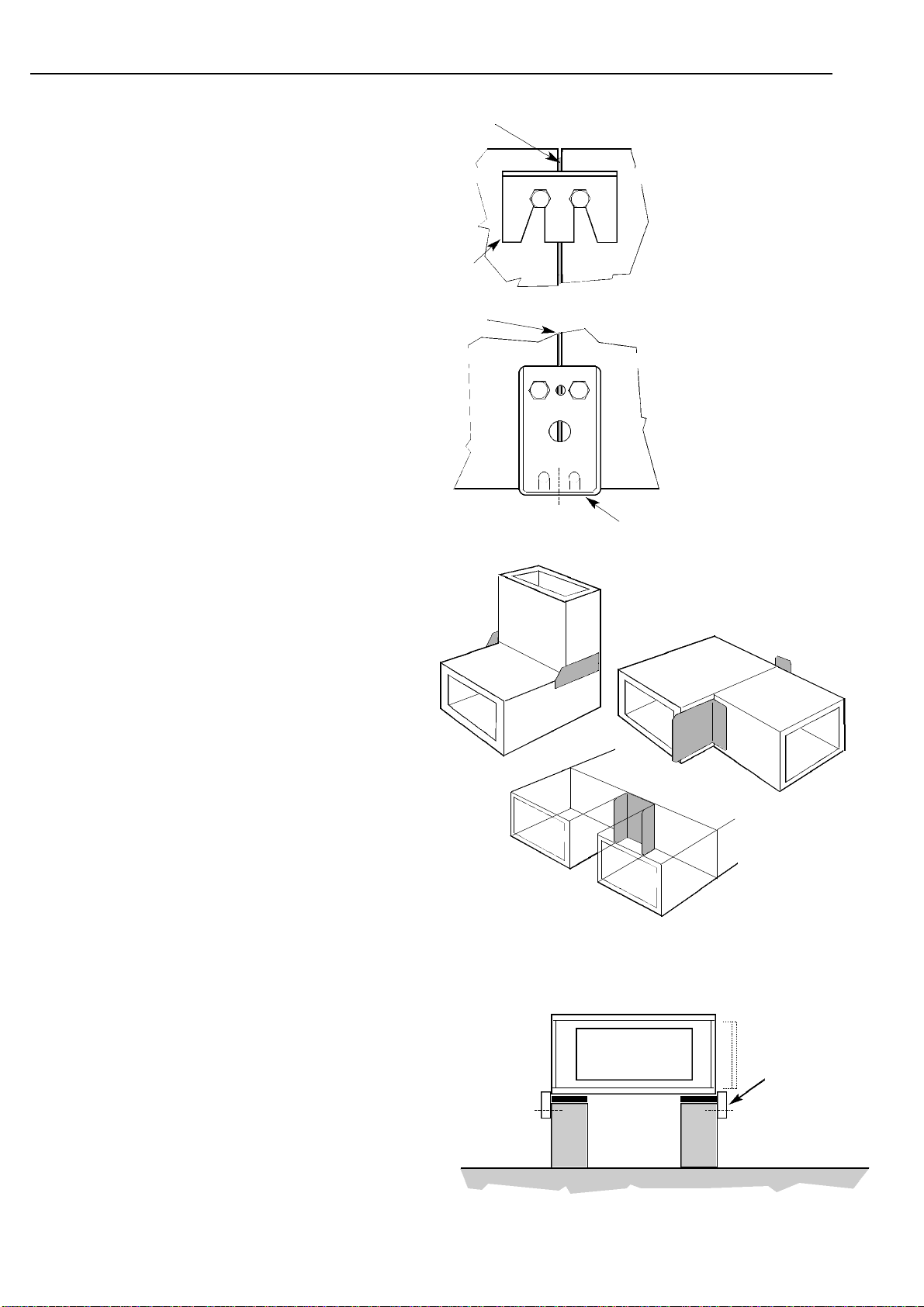
Gasket
Module Module
Mounting
foot
c/l of
mounting
fixing
2
Fig. 3 Fitting a cleat
Fig. 4 The mounting foot
Fig. 5 Closure Plates used on Bend and Heat Exchanger modules.
Fig. 6 Simple builders upstand mounting assembly.
Installation Options
The Boxer range can be installed using a number of
different methods. This provides flexibility to cater for
particular on site conditions. Note that for units delivered as
individual modules; the spigot plates that connect with the
ductwork are always fitted to the fan module. These should be
removed in preparation for fitting to the appropriate modules at
each end of the assembly.
Assembly of the modules
The module to module assembly is similar for all the unit sizes.
Each module is constructed from six panels. End panels are
designed to attach to the corresponding panel in the adjacent
module and provide mounting points for the assembly.
The modules are assembled together using cleats, mounting
feet or, for certain modules, closure plates.
All fixings necessary are provided. The fixings are vibration
proof.
Clamping cleats are manufactured in heavy gauge mild steel
and are designed to draw the end panels together into the
correct position for gasket compression. For fitting, slacken the
relevant vibration-proof bolts to show approximately 4mm of
exposed thread and slide the cleat into position. A sharp blow to
the folded edge will then engage the cleat. (See fig. 3). Tighten
the bolts to a torque of .........Nm.
Mounting Feet, pressed in mild steel, provide for both
attachment and mounting of the assembly. The vibration proof
bolts should be tightened to a torque of ........Nm.
Closure Plates, are supplied with the Bend Modules and also
the Heat Exchanger Modules. The vibration proof bolts should
be tightened to a torque of ........Nm.
NOTE:
In all cases when positioning adjacent modules, ensure
that the gasket material is not displaced.
Unit Mounting (floor or roof)
On a smooth and level surface, capable of supporting the
assembled weight of the units, no assembly frame is required.
This has the advantage of minimising the overall height of the
unit.
An uneven mounting surface will impose undue strain upon
the assembly. In extreme cases this may cause leakage and
component failure. A simple builders work upstand may be
used to raise the equipment from the floor level. (See fig. 6).
Note: this will be necessary where cooling coils and heat
exchangers are specified in order to allow fitting of the
appropriate condensate drainage trap.
Construct the upstand to support the base periphery of the
assembly. Position the modules in the correct order and a
assemble using clamping cleats. Mounting feet should be used,
at least at every other joint, secured to the mounting surface. It
is normal practice to fit a resilient matting between the unit and
the mounting surface.
Where supplied with a base frame the module assembly needs
only to be positioned and secured to the floor. Again, the
surface should be level and additional height may be required
for drainage traps.
Assemblies are supplied in maximum lengths of 2.4metres.
Longer assemblies must be joined on site (fixings supplied).
Gasket
Module
Cleat
Module
o
o
o
o
o
o
oo
Timber securing battens
used to retain the assembly
in position.
Note that the battens must
not be placed too high
around the assembly which
would interfere in removal
of the side access panels
Installation & Maintenance BOXER AIR HANDLING UNITS


