2
17. 05. 23. Document Number 672048
Nuaire | Western Industrial Estate | Caerphilly | CF83 1NA | nuaire.co.uk
BPS HP-COInstallation Manual
1.2 Important Information
This manual contains important information on the safe and
appropriate assembly, transport, commissioning, operation,
maintenance, disassembly and simple troubleshooting of the
product.
While the product has been manufactured according to the
accepted rules of current technology, there is still a danger
of personal injury or damage to equipment if the following
general safety instructions and the warnings contained in these
instructions are not complied with.
•Read these instructions completely and thoroughly before
working with the product.
•Keep these instructions in a location where they are
accessible to all users at all times.
•Always include the operating instructions when you pass
the product on to third parties.
1.3 Personal Protective Equipment
The following minimum Personal Protective Equipment (PPE) is
recommended when interacting with Nuaire products:
•Protective Steel Toed Shoes - when handling heavy objects.
•Full Finger Gloves (Marigold PU800 or equivalent) - when
handling sheet metal components.
•Semi Fingerless Gloves (Marigold PU3000 3DO or
equivalent) - when conducting light work on the unit
requiring tactile dexterity.
•Safety Glasses - when conducting any cleaning/cutting
operation or exchanging filters.
•Reusable Half Mask Respirators - when replacing
filters which have been in contact with normal room or
environmental air.
Nuaire would always recommend a site specific risk assessment
by a competent person to determine if any additional PPE is
required.
2.0 INTRODUCTION
2.1 OPERATION
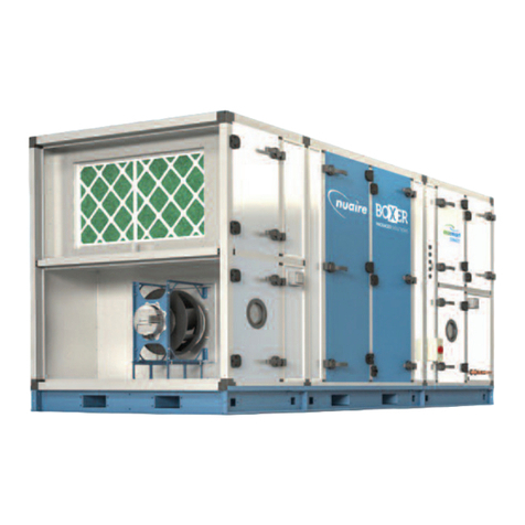
The packaged supply and extract unit shall be manufactured from
Magnelis corrosion resistant steel, with 50mm double skinned
panels and anodized aluminium frame. All external fittings and
fixings shall be stainless steel, aluminium or non-metallic. All
panels and frames will be of a totally thermally broken design,
complying with the following specification in accordance with The
unit shall include the following items: -
•Thermal Wheel HX: A high eciency, ERP compliant heat
exchanger with automatic bypass, complete with condensate
trays.
•G4 pre-filter and F7 main supply filters shall be fitted with
a single M5 bank present on the extract side. Slides for
alternative panel and bag options shall be present and
pressure drop monitoring for maintenance notification will be
included. Performance optimised backward curved impellers
and IP54 EC motors shall be used to provide low specific
fan powers and stepless speed control without tonal noise
generation.
•Fan pressure transducers shall be fitted for constant
pressure/flow control and energy monitoring.
•Internal lighting and inspection portholes shall be present on
all fan modules.
•An electric -up heater battery shall be fitted on EHP units,
complete with power controller to allow output modulation
from the unit control.
•A fail-safe auto-reset safety device shall be present.
•Internally installed Heat recovery ASHP with dual compressor
operation.
All hinged access panels shall be lockable and removable
(with a common key for all) allowing full maintenance access
from the side. The unit has the option of left hand or right hand
arrangements in direction of supply air flow.
Each Ecosmart heat pump system is charged with R32 refrigerant
gas and is controlled via Carel C.pco plc controllers, each heat
pump system will operate to control the supply air temperature
(set via the BPS Ecosmart control).
Each system will recover and utilise heat from the exhaust air DX
coil of the BPS unit and transfer this heat/energy eciently via
the refrigeration cycle to the supply air DX coil in heating mode.
Each system will also oer pre-cooling of the supply air (set
temperature by BPS Ecosmart controller).
The heat pump systems are installed between the thermal
wheel allowing for very ecient heat recovery system. The
complete Heat pump system can slide out for easy of service and
maintenance works.
1 BPS-ECO-HP Animation QR Code
or CLICK HERE to see the animation
2.2 Dual Compressor System
Automatic Defrost Control strategy – when the build-up of frost in
the exhaust coil reaches a limit the dual system will automatically
respond and start warming up the second system (on completion
of system that is in defrost, it will not start when the defrost is
active) to ensure the unit provides continuous ventilation.
In very cold conditions an electric back-up heater is installed in
the supply air reducing any risk of cold air being supplied to the
building, this heater can also be used as backup in case of a heat
pump system failure.
Lower Energy Consumption – A dual compressor system
uses less energy than one large single system providing the
opportunity to make energy savings whilst ensuring the total
energy consumed is minimized.
Greater longevity – A dual system with duty share will prolong the
working life of the components.
•Guaranteed ventilation 24/7 – A dual system will still provide
50% ventilation to the building if the one system fails.


