2
26. 08. 21. Document Number 671827
Nuaire | Western Industrial Estate | Caerphilly | CF83 1NA | nuaire.co.uk
BPS H-ES
Installation Manual
1.2 Important Information
This manual contains important information on the safe and
appropriate assembly, transport, commissioning, operation,
maintenance, disassembly and simple troubleshooting of the product.
While the product has been manufactured according to the accepted
rules of current technology, there is still a danger of personal injury or
damage to equipment if the following general safety instructions and
the warnings contained in these instructions are not complied with.
•Read these instructions completely and thoroughly before
working with the product.
•Keep these instructions in a location where they are accessible
to all users at all times.
•Always include the operating instructions when you pass the
product on to third parties.
1.3 Personal Protective Equipment
The following minimum Personal Protective Equipment (PPE) is
recommended when interacting with Nuaire products:
•Protective Steel Toed Shoes - when handling heavy objects.
•Full Finger Gloves (Marigold PU800 or equivalent) - when
handling sheet metal components.
•Semi Fingerless Gloves (Marigold PU3000 3DO or equivalent)
- when conducting light work on the unit requiring tactile
dexterity.
•Safety Glasses - when conducting any cleaning/cutting operation
or exchanging filters.
•Reusable Half Mask Respirators - when replacing filters which
have been in contact with normal room or environmental air.
Nuaire would always recommend a site specific risk assessment by a
competent person to determine if any additional PPE is required.
2.0 INTRODUCTION
The information contained in this document provides details of
installation, operation and maintenance for installers and users of the
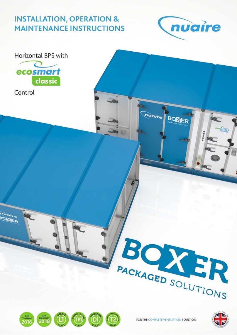
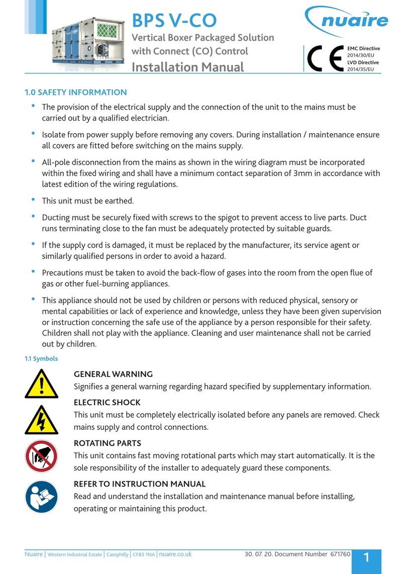
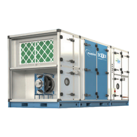
BOXER PACKAGED SOLUTION (BPS) AHU units with heat recovery.
The BPS AHU range, is manufactured from Aluzinc corrosion resistant
steel, with 50mm double skinned panels and anodized aluminium
frame of a totally thermally-broken design, complying with the
following specification in accordance with BS EN 1886: Mechanical
strength, D1; Leakage class, L1; Thermal transmittance, T2; Thermal
bridging, TB1.
This range includes high efficiency centrifugal fans with EC motors, a
high efficiency thermal wheel or plate heat exchanger, G4 pre-filtration
and F7 main filtration of the supply air and M5 filtration of the extract
air.
Optional heating (LPHW or Electric) model variants are available.
Ancillaries including but not limited to attenuators, dampers, weather
terminals and frost modules are available from Nuaire.
These units are supplemented with the EcoSmart Classic (ES) control
platform. General information regarding performance and specification
for the equipment is available via our technical literature, and/or
project specific documentation.
2.1 Code Description:
B 8 05 H / L R / ES - L
| | | | | | | |
1 2 3 4 5 6 7 8
1. Range: B = Boxer Packaged Solution
2. ErP Compliance Year: 8 or No Affix = 2018
3. Unit Size: 05, 10, 15 or 20
4. Heat Recovery Type: H = Horizontal Plate
5. Heating Type: E= Electric
L = Low Pressure Hot Water (LPHW)
N = No Heating
6. Cooling Type: N = No Cooling
7. Control Type: ES = Classic
8. Access Handing L = Left Hand
(in direction of supply R = Right Hand
airflow)


