2
27. 04. 21. Document Number 671182
Nuaire | Western Industrial Estate | Caerphilly | CF83 1NA | nuaire.co.uk
GENIEInstallation Manual
1.2 Important Information
This manual contains important information on the safe and
appropriate assembly, transport, commissioning, operation,
maintenance, disassembly and simple troubleshooting of the product.
While the product has been manufactured according to the accepted
rules of current technology, there is still a danger of personal injury or
damage to equipment if the following general safety instructions and
the warnings contained in these instructions are not complied with.
•Read these instructions completely and thoroughly before
working with the product.
•Keep these instructions in a location where they are accessible
to all users at all times.
•Always include the operating instructions when you pass the
product on to third parties.
1.3 Personal Protective Equipment
The following minimum Personal Protective Equipment (PPE) is
recommended when interacting with Nuaire product:
•Protective Steel Toed Shoes - when handling heavy objects.
•Full Finger Gloves (Marigold PU800 or equivalent) - when
handling sheet metal components.
•Semi Fingerless Gloves (Marigold PU3000 3DO or equivalent)
- when conducting light work on the unit requiring tactile
dexterity.
•Safety Glasses - when conducting any cleaning/cutting operation
or exchanging filters.
•Reusable Half Mask Respirators - when replacing filters which
have been in contact with normal room or environmental air.
Nuaire would always recommend a site specific risk assessment by a
competent person to determine if any additional PPE is required.
2.0 INTRODUCTION
The Genie range of fans has been specifically designed to ventilate
small rooms such as toilets, bathrooms, cloakrooms etc. and can be
surface and recessed mounting. An optional window mounting kit is
available for this unit, code ref: WINKIT.
Air entering the unit passes through a washable filter fitted to the front
cover. Backdraught shutters, retained in the closed position when fan is
not running, are fitted to the base plate.
Motor has sealed, self lubricating bearings and “heatseeker” thermal
overload protection. The fan/ motor assembly is retained by spring clips
to simplify maintenance.
Interchangeable plug in electronic control modules can incorporate:
•Run-On Timer
•Humidistat
•Continuous Low Duty With Boost
As a safety feature the fan/motor assembly is automatically
disconnected when the electronic control module is removed.
When installing Genie units for remote switching it is important
that the pull cord (if fitted) is removed.
It is recommended that the unit is switched off (by the pull cord)
before cutting. Cut the pull cord inside the unit a little way beyond
the control module.
2.1 Code Description:
GENIE - H 12
1- 2 3
1. Range: GENIE: Universal Surface Mounted Fans
2. HX Type: No Affix: On/Off Control Via Pull Cord / Remote
Switch*
PIR: On/Off Control Via Pir (230 V Only)
S: On/Off Control With Integral Run-On
Timer Via Remote Switch* Only
H: On/Off Control With Integral Humidistat
Via Pull Cord / Remote Switch*
X: Continuous Trickle With Boost Via Pull
Cord / Remote Switch*
XH: Continuous Trickle With Boost Via Pull
Cord / Remote Switch*
3. Supply Voltage: No Affix: 230 V
12: 12 V
*Light switch or similar (not supplied).
Genie units are supplied with a finishing frame for use in semi-
recessed applications.
WINKIT: Optional window mounting kit.
3.0 MECHANICAL INSTALLATION
Installation must be completed by competent persons, in accordance
with good industry practice and should conform to all governing and
statutory bodies i.e. IEE, CIBSE, etc.
Before commencing work make sure that the unit is electrically
isolated from the mains and switched live supply.
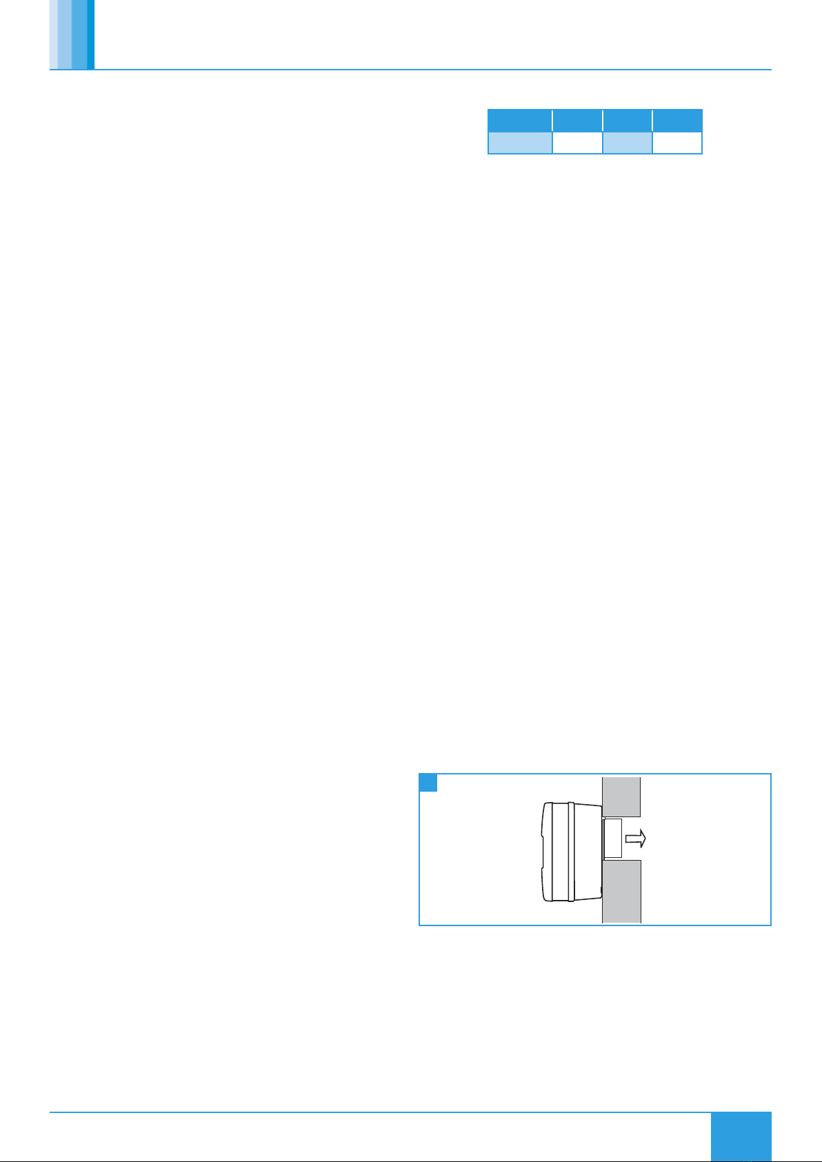
3.1 Surface Mounting
It is assumed that a solid mounting position has been selected,
compatible ductwork has been installed and passages for ductwork
from the outlet spigot as well as electrical connection have been
prepared.
The discharge spigot is 98mm Ø OD. The hole in the structure
should therefore be of a dimension to accommodate any ducting or
cavity lining used.
Base drill pattern superimposed in Section 10.0 on page 8.
1 Wall Mounted Unit


