5
27. 01. 22. Document Number 671398
Nuaire | Western Industrial Estate | Caerphilly | CF83 1NA | nuaire.co.uk
OPUS(40/60/95)Installation Manual
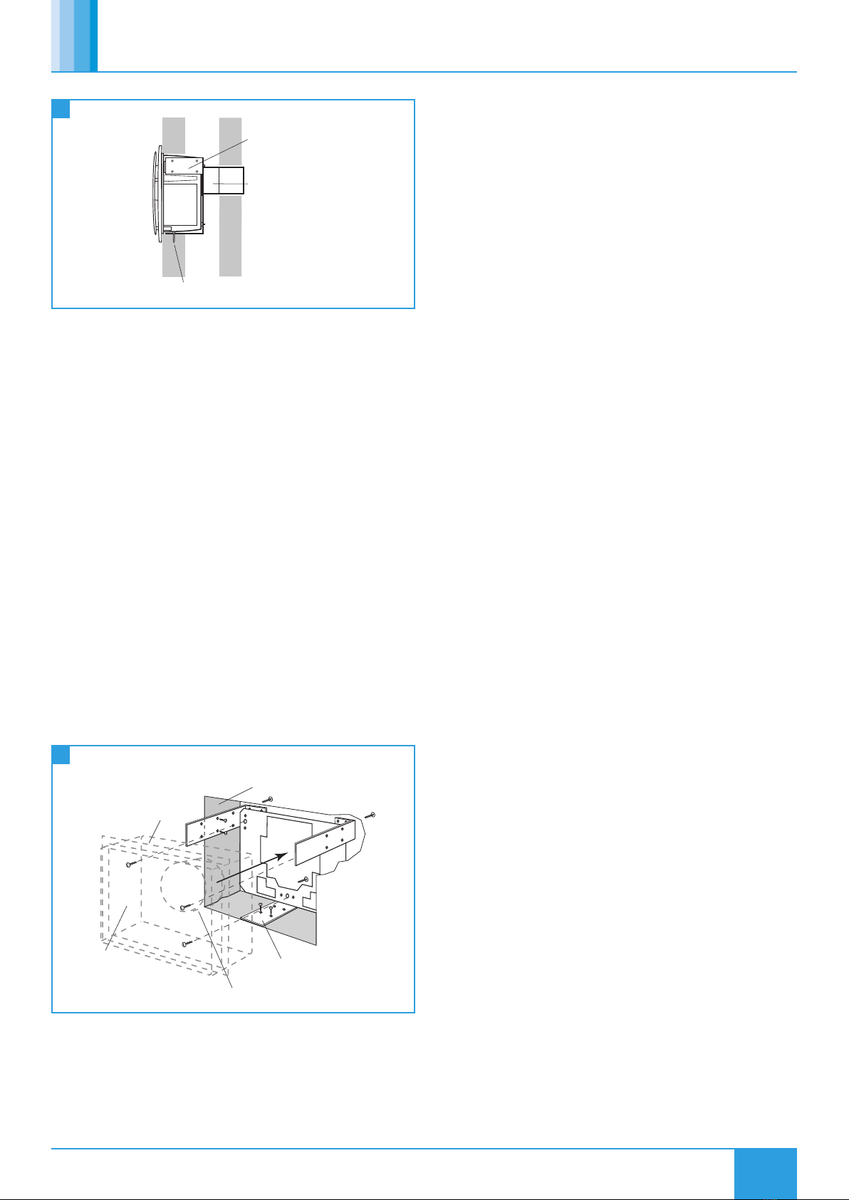
3.3 Recess Mounting With Rear Spigot
Wall fixings through
mounting frame
Rear mounted
spigot
of mounting
Side bracket
frame
11 Recess Mounted In Cavity Wall
For applications including cavity walls that require rear spigot
configuration.
1. Unpack the unit and components. Discard the top spigot (040918),
rear spigot blank (040917) and outer casing (040915). Fit the recess
flange (040919) and rear spigot (040954). Remove the front cover/
grille and disconnect the motors from the control circuit board,
noting their orientation. Rotate the yellow retaining clip and remove
the fan assembly. Leaving the control unit in place, remove the top
section only.
2. The unit should not be mounted directly to partition wall / ceiling
but a suitable frame should be erected to secure the mounting
frame kit to (Figure 12).
3. Run suitable cable into the unit, noting the wiring should be for a
fixed wired installation.
4. Run any ancillary wiring into the knock out “square”.
5. Secure the case to the frame using the machine screws provided
taking care not to twist or distort the case.
6. Connect all wiring (Section 4.5) and re-fit top section of control
unit. Re-fit fan assembly and connect motors to control board.
Rotate yellow clip to lock in place.
7. Complete the installation by securing the front cover and fitting any
filters, test-run the unit.
8. Adjust control settings as required.
Cut bracket flush with
mounting surface of wall
Fan unit rear spigot fits into back of mounting
frame and into ducting
Fan Unit
An aperture of 310mm x 220mm
is required for fan and mounting kit
Recessed mounting flange
MS screws
Self tapping screws x 3
12 Recess Mounted Frame Kit In Wall Aperture With Rear Spigot
Configuration
4.0 ELECTRICAL INSTALLATION
Isolation - Before commencing work, make sure that the unit and
Nuaire control are electrically isolated from the mains supply.
For good EMC engineering practice, any sensor cables or switched
live cables should not be placed within 50mm of other cables or on
the same metal cable tray as other cables.
4.1 Ecosmart Control Connections
4.1.1 Net Connections
The IDC plug-in connectors are provided for the connection of
compatible sensors, manual controls and for linking the fans together
under a common control. If more than 3 connections are required, the
junction box (product code ES-JB) should be used.
Do not run the SELV data cable in the same conduit as the mains
cable and leave a 50mm separation with any power cables.
4.1.2 Volt Free Relay Contacts
The volt free contacts are not fused. If these are used to power any
external equipment, the installer must provide adequate fusing or other
protections. These contacts are rated at 5A resistive, 0.5A inductive.
4.1.3 Run Connections
These contacts are closed when the fan is running.
Fault connections:
No Fault = Contacts Close
Fault = Contacts Open (Including No Power Supply to Unit)
4.1.4 Data Cable Installation
A 4-core SELV data cable is used to connect devices such as sensors
to the fan and for interconnecting multiple fan units. Do not run
data cable in the same conduit as the mains cables and ensure there
is a 50mm separation between the data cable and other cables. The
maximum cable run between any two devices is 300m when it is
installed in accordance with the instructions. Please note that the
total data cable length used in any system must be less than 1000m.
Keep the number of cable joints to a minimum to ensure the best data
transmission efficiency between devices.
4.1.5 Maximum Number of Devices
The maximum number of devices (including fans) that can be
connected together via the cable is 32, irrespective of their functions.
4.1.6 LED Indication
PWR / GREEN: Power on and OK,
STANDBY RED: LED On When Fan is Not Running
Fan 1 GREEN: Fan 1 is running, RED: Fan 1 faulty.
Fan 2 GREEN: Fan 2 is running, RED: Fan 2 faulty.
4.2 Basic Control Connections
4.2.1 Fault (Terminals 2 and 3)
This should only be used with optional OPUS-RFI (remote fail
indicator). Connecting mains or any other device will damage the
control PCB.
4.2.2 LED Indication
Fan 1 GREEN: Fan 1 is running.
RED: Fan 1 faulty.
Fan 2 GREEN: Fan 2 is running.
RED: Fan 2 faulty.