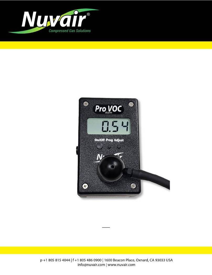
Nuvair Pro N2 Alarm User manual

User Manual
Pro N2Alarm
Nitrogen Analyzer
Rev. 07.18

Pro N2Alarm nitrogen Analyzer
Nuvair Page 2 www.nuvair.com
If you have any questions on this equipment please contact Technical Support at:
Nuvair
1600 Beacon Place
Oxnard, CA 93033
Phone: +1 805 815 4044
FAX: +1 805 486 0900
Email: info@nuvair.com
Hours: Monday through Friday
8:00 a.m. to 5:00 p.m. PST USA
This User Manual contains important safety information and should always be
available to those personnel operating this equipment. Read, understand and retain all
instructions before operating this equipment to prevent injury or equipment damage.
Every effort was made to ensure the accuracy of the information contained within this manual;
however, we retain the right to modify its contents without notice. If you have problems or questions
after reading the manual, stop and call for information.

Pro N2Alarm nitrogen Analyzer
Nuvair Page 3 www.nuvair.com
Table of Contents
1.0Introduction ........................................................................................................4
2.0System Description …………………………………………………………….........5
2.1Controls …………………………………………………………...................6
2.2Display ………………………………………………………….....................6
2.3Alarm ...................................................................................................... 6
2.4Sensor …………………………………………………................................6
2.5Batteries ……………………………………………………………...............6
2.6Flow Adapter Cap ..............………………………………………………....7
3.0Calibration ……………………………………………….………………..................7
3.1Calibration Methods ………………………………………………………… 8
4.0Operation............................................................................................................8
4.1Programming Procedures ………… ………………………………............9
4.2Alarm Setting …………………………………………….............................10
4.3 Full Scale Value Setting …………………………………………………….10
4.4 Calibration nitrogen Value ……………………… ………………………... 11
5.0Threshold Alarms .............................................................................................. 12
6.0Powering on and warming up ……………………………………………………… 13
6.1 Powering Off..………………………………………………………………...13
7.0 Factory Reset ………………………………………………………………………..14
8.0 Maintenance…………………………………………………………………………. 14
8.1Analyzer Care …………………………………………………….................14
8.2Battery Replacement …………………………………………………..........15
8.3Sensor Replacement …………………………………………….................15
8.4 Handling Sensors ..…………………………………………………………. 16
9.0 Sensors ………….. …………………………………………………………………. 18
10.0 Troubleshooting...............................................................................................18
11.0 Spares and accessories ………..…………….…………………………………...19
12.0 Relay Output Schematics…………………………………………………………. 20
Warranty …………………….…………………………………………….……... 21

Pro N2Alarm nitrogen Analyzer
Nuvair Page 4 www.nuvair.com
1.0Introduction
This manual will assist you in the proper set-up, operation and maintenance of the Pro N2
Alarm nitrogen Analyzer. Be sure to read the entire manual.
Throughout this manual we will use certain words to call your attention to conditions,
practices or techniques that may directly affect your safety. Pay particular attention to
information introduced by the following signal words:
Indicates an imminently hazardous situation, which if not avoided, will result in serious
personal injury or death.
Indicates a potentially hazardous situation, which if not avoided, could result in
serious personal injury or death.
Indicates a potentially hazardous situation, which if not avoided, may result in minor or
moderate injury. It may also be used to alert against unsafe practices.
Notifies people of installation, operation or maintenance information which is
important but not hazard-related.
Warnings Graphics Defined:
Gas Inhalation Skin damage

Pro N2Alarm nitrogen Analyzer
Nuvair Page 5 www.nuvair.com
2.0System Description
The Pro N2 Alarm nitrogen analyzer measures nitrogen (N2) levels in gases in the range of
0.0 to 100%. The Analyzer is designed to verify N2concentration in stored gas cylinders,
enclosed spaces and with compressors pumping nitrox. When used in breathing gas
applications, redundant Analyzers must be used for verification. In diving, for example, one
Analyzer must be used to monitor nitrogen during breathing gas production and a second
independent Analyzer must be used to verify the nitrogen content of the stored breathing gas
prior to diver use.
When using the Analyzer for diving applications with mixed gases other than air, you
must first obtain proper instruction from a certified diving instructor with a nationally
recognized training agency qualified in mixed gas diving. Improper use of this analyzer
may result in incorrect gas analysis which can lead to serious personal injury or death.
The Analyzer is battery powered and includes an
internally mounted Sensor with audible alarm. The
Water-Resistant Case includes a Digital Display and
controls that are environmentally sealed
The Analyzer uses a Flow Adapter Cap and Flexible
tubing to deliver sample gas to the Sensor.
Pressurized gases must be regulated to avoid
damage to the analyzer. Use of this Analyzer in a
hyperbaric chamber will void the owner’s warranty.
The Analyzer comes in a high impact storage case.
It is ready for use after calibration with an
appropriate certified calibration gas.
This analyzer is designed for use at atmospheric pressures only. It is not designed for
exposures in a hyperbaric chamber. Use of this analyzer in a hyperbaric chamber will
result in incorrect readings and may damage the unit.
Although the Analyzer is a rugged instrument, careless handling or abuse may result
in damage to the Analyzer resulting in inaccurate gas analysis. Inaccurate gas analysis
can lead to serious personal injury or death.
Breathing gas must always be analyzed by two separate Analyzers, with one used for
production and one used for analysis after production. Never depend on a single
Analyzer during both gas production and delivery. If the Analyzer readings do not
agree, both units must be recalibrated. Inaccurate gas analysis can lead to serious
personal injury or death.
Flow
Adapter Cap
Over Sensor
Face
Water-
Resistant
Case

Pro N2Alarm nitrogen Analyzer
Nuvair Page 6 www.nuvair.com
2.1.Controls
2.2.Display
2.3.Alarm
The Analyzer includes an audible alarm that is activated when the sensor reaches a user
programmed minimum % of nitrogen and/or maximum % of nitrogen. The alarm will not clear
until the concentration of N2returns within the parameters programmed by the user. The
alarm function may be activated and deactivated, and must be re-activated every time the
analyzer is powered on.
2.4.Sensor
The Analyzer uses a electrochemical sensor that measures content in gases. The sensor is
disposable and user-replaceable, with a life expectancy of up to 48 months, depending on
usage. The sensor is designed for use at atmospheric pressure (0 psi.). The gas mixture to
be analyzed must be regulated accordingly and any potential for pressure or vacuum must be
avoided.
2.5.Batteries
One 9 volt battery provides power. The battery is located inside the Analyzer and is user-
replaceable. The battery should be removed any time the Analyzer will be stored without use
for extended periods of time. The screen will blink alternately from “000” to “bAt” at start up
when battery is low.
Digital
Display
On/Off Button
Low Battery
Indication
Adjust Button
Relay
Output
Program Button
Active nitrogen
Reading
0 – 100 %
In .1% increments

Pro N2Alarm nitrogen Analyzer
Nuvair Page 7 www.nuvair.com
2.6.Flow Adapter Cap
The Analyzer includes a Flow Adapter Cap with flexible tubing and flow orifice. It attaches to
the Sensor port and is sealed by an o-ring. It can be used to direct the gas sample flow to the
Sensor via one of two methods:
Flow to the sensor must be restricted to 2.0 Liters Per Minute (L/min) maximum. Nuvair offers
flow restrictors to accomplish this task. See appendix.
3.0Calibration
Nitrogen Analyzers must be calibrated before each use. Improper calibration may
result in the use of incorrect breathing gas mixtures, which may cause serious injury
or death to the person using the gas mixture.
Calibration or use of the Analyzer with a low battery may result in inaccurate readings.
Inaccurate gas analysis can lead to serious personal injury or death.
When Analyzer calibration is performed at different atmospheric conditions than the
gas being measured, a calibration correction value may be required. Improper
calibration may result in the use of incorrect breathing gas mixtures, which may cause
serious injury or death to the person using the gas mixture.
If the Analyzer has been subjected to a recent change in ambient temperature, allow it
to stabilize for one hour before checking calibration.
During the warm up time, if the nitrogen percentage of the mixed gas flow is different
from the value of calibration set in the instrument, a failed calibration is obtained and a
wrong analysis value will be displayed.
Sample Flow Method
Flow is Delivered from
Low Pressure Source
via Flexible Tubing
Direct Flow Method
Flow is Directed to
Flow Orifice on Face
of Flow Adapter Cap
Vent Hole

Pro N2Alarm nitrogen Analyzer
Nuvair Page 8 www.nuvair.com
3.1.Calibration Methods
Calibration should always be performed at the same temperature and humidity conditions as
the gas being measured. This is not always possible, for example, in a tropical environment
where dry breathing gas from a high-pressure SCUBA cylinder will be measured after
Analyzer calibration has been performed in the warm, humid ambient air. Under these
conditions a calibration correction value may be required, or dry air must be used for
calibration. It may be required for the analyzer to be calibrated to a certified calibration gas.
Obtain proper training before attempting special calibration procedures. Improper
calibration may result in the use of incorrect breathing gas mixtures, which may cause
serious injury or death to the person using the gas mixture.
To assure the greatest accuracy, use a Calibration Gas with a nitrogen concentration as
close as possible to the expected concentration in the gas being produced.
4.0 Operation
Prior to each Analyzer use:
1) Remove the flow adapter cap to expose the sensor to ambient air, OR start the flow of
Calibration Gas. Calibration gas must contain 20.9- 21% oxygen.
2) Turn unit the on by holding the “On/Off” button until the display shows “On”, then release
the button. The “Att” (Wait) message will be displayed, followed by the software version.
3) The analyzer stores the previous calibration values, which need to be reset.
4) To calibrate, depress and hold the “On/Off” and “Adjust” buttons until the screen
changes. Release the buttons and wait until the screen reads 79.0.
5) Install the flow adapter cap on the sensor.
6) The instrument is now ready to read nitrogen concentration of the gas. You may now
begin nitrogen production.
7) The display will now show the nitrogen percentage of the gas.
8) ANY TIME THE ANALYZERS ARE RE-CALIBRATED THE SENSORS MUST BE
EXPOSED TO AMBIENT AIR. REMOVE THE FLOW ADAPTER CAPS AND LET THE
SECURE THEM OUT OF THE WAY IN SUCH A MANNER THAT ANY NITROGEN
ESCAPING FROM THEM WILL NOT AFFECT THE CALIBRATION READING.
Tip: You can check the battery life and current temperature by holding Adjust button for 3
seconds. The display will alternate from battery life to current temperature (Celsius) twice
before returning the home screen.

Pro N2Alarm nitrogen Analyzer
Nuvair Page 9 www.nuvair.com
Gas, even under moderate pressures, can cause extreme bodily harm. Never allow any
gas stream to be directed at any part of your body.
Never expose the sensor to pressures above atmospheric pressure (0 psi) or you may
cause damage to the sensor and/or receive false readings. Damaged Sensors will not
provide accurate gas analysis. Inaccurate gas analysis can lead to serious personal
injury or death.
4.1.Programming Procedures
Press the “Prog” button until “Pr” appears on the display. The display will then
change to “AL 1”and alternate with the 3 digit set value.
It is possible to program:
oAL 1 Minimum alarm point expressed in % of nitrogen concentration
oAL 2 Maximum alarm point expressed in % of nitrogen concentration
oFSC Value expressed in % of nitrogen concentration corresponding to the
current output full scale value (20mA). 20mA always correspond to 100%
nitrogen concentration.
oO2c nitrogen sensor calibration point
At the end of the programming procedure the display will show “End” and the
instrument will display the nitrogen content of the gas mix.
Below are the actual screen views of each of the modes:
Program
First Alarm
Full Scale Value
Second Alarm
Nitrogen Sensor
Calibration
21% reading

Pro N2Alarm nitrogen Analyzer
Nuvair Page 10 www.nuvair.com
4.2.Alarm Setting (AL 1 & Al 2)
1.) Press the “Prog” button for more than two seconds and then release the button.
“Pr”will appear on the display, followed by “AL 1” and the currently set value in
N2% (0% default) alternating.
2.) The blinking digit shows the cursor position.
3.) Press the “Prog” button to increase the value (from 0 to 9)
4.) Press the “Adjust”button to move the cursor to the next digit, the “Adjust”button
will be used to cycle through the rest of the digits.
5.) To complete your entry and save the N2% value, press the “On/Off”button. You
will then automatically jump to “AL 2” programming view.
6.) Repeat steps 3 through 5 to modify and save the “AL 2”N2% desired value (100%
default).
7.) To complete your entry and save the alarm values press the “On/Off”button. The
display will then scroll to the “FSC” programming view. Or continue to press the
“On/Off” button until the “End” screen appears.
4.3.Full Scale Value Setting (FSC)
It is not necessary to modify this value which is factory set at 100. This value corresponds
to 100% nitrogen, which translates to 20mA at the analog output. 4mA is the value at 0%
of nitrogen. This value can be changed in the same manner as the Alarm settings:
1.) Press the “Pro” button for more than two seconds and then release the button.
On the display will appear “Pr” for two seconds, then “AL 1” will appear. Press the
“On/Off”button to cycle through the Alarm settings until you reach the “FSC” view.
“FSC” and a 3 digit value will then alternate.
2.) The blinking digit shows the cursor position.
3.) Press the “Pro” button to increase the value (from 0 to 9)
4.) Press the “Adjust”button to move the cursor to the next digit, the “Adjust”button
will be used to cycle through the rest of the digits.
5.) To complete your entry and save the “FSC”value, press the “On/Off”button. The
display will then scroll to “O2c”programming view. Or continue to press the
“On/Off”button until the “End” screen appears.

Pro N2Alarm nitrogen Analyzer
Nuvair Page 11 www.nuvair.com
4.4.Calibration nitrogen Value (O2c)
The “O2c” value is the calibration value assigned based on the percentage of oxygen in
the gas being analyzed. The default calibration value is 21.0 (corresponding to 21% O2
and 79% N2in ambient air). It is not necessary to modify this value if the unit is always
calibrated in ambient air.
1.) Press the “Prog” button until “AL 1” appears on the display. Use the “On/Off” button
to cycle through the settings until you reach the “O2c” screen.
2.) The blinking digit shows the cursor position.
3.) Press the “Pro” button to increase the value (from 0 to 9)
4.) Press the “Adjust” button to cycle through the digits.
5.) To complete your entry and save the O2c value, press the “On/Off” button.
The nitrogen calibration value will be the same value of the calibration set when the
instrument is switched on. If, during auto-calibration the nitrogen percentage of the
gas flowing across the sensor is a different value from calibration set in the instrument,
a failed calibration is obtained and the wrong gas percentage will be displayed. Wrong
nitrogen analysis may lead to death.
The calibration value of the Pro N2Alarm is factory set at 21% and any adjustments to
this value will change the analyzers ability to properly ready the % of nitrogen in a gas.
A wrong value in this parameter will give a wrong reading of N2concentration and the
instrument will not be accurate. All the analysis concentration shown on the display
will be wrong. If you modify this setting you must test the analyzer for accuracy with
certified testing gas. Do not modify this value. Wrong nitrogen analysis may lead to
death.

Pro N2Alarm nitrogen Analyzer
Nuvair Page 12 www.nuvair.com
5.0Threshold Alarms
The Alarm function must be activated every time the unit is powered on. To activate,
wait until the unit has cycled through its startup and is steadily displaying the
analyzer’s reading. Press the On/Off and Prog buttons at the same time until an arrow
appears on the left side of the display.
Should the nitrogen reading exceed the threshold alarms (AL1 or AL2), the instrument
will go into alarm mode and activate the (optional) relay output (open collector max
100mA) and the audible alarm. The display will show the trespassed alarm and the
actual measured value. To stop the audible alarm, press any key. In this event the Pro
N2Alarm Analyzer will remain in alarm mode until the analyzed value goes below the
alarm.
The relay output typically is used to shut down the compressor. Nuvair can supply the
necessary components to adapt your compressor to the relay or provide them at the
time of install on a new compressor.
To deactivate the alarms, press the On/Off and Prog buttons at the same time until
the arrow goes away.

Pro N2Alarm nitrogen Analyzer
Nuvair Page 13 www.nuvair.com
6.0 Powering on and warming up
Before powering on the unit, ensure the sensor is exposed to a gas mixture with the 21%
oxygen. This value corresponds to 79% nitrogen and 21% oxygen in ambient air. Be sure that
air flowing across the sensor is 21% oxygen (if using the default setting) before turning on
the analyzer.
Press the “On/Off”button and hold until the display shows “ON”. The “Att” (wait) message
will then be displayed for several seconds.
Perform calibration as described in Section 4.0.
Activate the alarm function by pressing the Press the On/Off and Prog buttons at the same
time until an arrow appears on the left side of the display.
If the nitrogen percentage of the gas flowing across the sensor during calibration, a
failed calibration is obtained and the wrong gas percentage will be displayed. Wrong
nitrogen analysis may lead to death.
6.1. Powering Off
At the home or gas reading screen, hold down the “On/Off”button for a couple of
seconds. The Analyzer will display “OFF” and then go blank.

Pro N2Alarm nitrogen Analyzer
Nuvair Page 14 www.nuvair.com
7.0 Factory Reset
In case it is necessary to reset the Pro N2Alarm Analyzer to the factory settings, power on
the Analyzer by pressing “On/Off” and “Adjust” buttons simultaneously. The display will flash
“res”, then scroll to the programming menu.
The Alarms, FSC value, and O2c value will all need to be checked and/or reprogrammed at
this point.
In case of reset, the instrument will delete all the alarms settings, the full scale value,
and any new conversion value of nitrogen sensor will be reset to factory settings.
Before using again the instrument, it may be necessary to program again the alarm
values, the full scale value, and the nitrogen sensor calibration if changed. All the
analysis concentration shown on the display would be wrong. Wrong nitrogen analysis
may lead to death.
8.0 Maintenance
8.1. Analyzer Care
Analyzers immersed in liquid or stored in wet environments may not operate properly.
This may result in incorrect readings. Incorrect gas analysis may result in personal
injury or death.
Protect the analyzer from excessive shock and impact. Excessive shock and impact
may result in incorrect readings. Incorrect gas analysis may result in personal injury
or death.
Protect the analyzer from exposure to hyperbaric environments. Exposure to
hyperbaric environments may result in incorrect readings. Incorrect gas analysis may
result in personal injury or death.
•Do not clean Analyzer with anything other than a damp soft cloth.
•Do not immerse in liquid, leave unprotected outside, or store in a wet environment.
•Protect Analyzer from excessive shock and impact.
•Protect Analyzer from excessive exposure to sunlight and extreme temperatures.
•Do not use the Analyzer in a hyperbaric environment.

Pro N2Alarm nitrogen Analyzer
Nuvair Page 15 www.nuvair.com
8.2. Battery Replacement
Be sure to dispose of spent, leaking, or damaged Battery properly, according to local
regulations.
The following pictures illustrate the steps required to replace the batteries in the Analyzer.
8.3. Sensor Replacement
The replacement sensor for the N2 Analyzer is part number: 9507M.
You may take note of your sensor number before installing a new sensor serial
number.
Be sure to dispose of spent, leaking, or damaged Sensors properly, according to local
regulations.
Do not swallow (ingest) either the electrolyte from the Sensor or the Sensor itself. The
Potassium hydroxide chemical contained in the Sensor will cause severe injury or
death.If electrolyte or the Sensor is swallowed, seek medical attention immediately.
Step 1. Remove
Screws
Step 2. Remove
Back Cover
Step 3.
Remove &
Replace Old
Battery
Step 5.
Reinstall
Screws
Step 4. Replace
Back Cover -
Do Not Pinch
Wires
Step 6. Turn
Analyzer On
Step 7.
Perform
Calibration
Sensor Serial
Number

Pro N2Alarm nitrogen Analyzer
Nuvair Page 16 www.nuvair.com
If after handling the Analyzer or Sensor, you find that your fingers or
other parts of your body feel “slippery” or the skin or eyes sting,
immediately flush affected area with clean, fresh water for at least 15
minutes. The stinging or slippery sensation is an indication of a leaking Sensor. The
Potassium Hydroxide chemical contained in the Sensor can cause severe injury or
death. Seek immediate medical attention if eye contact is made or skin stinging
persists.
8.4. Handling Sensors
Replacement Sensors are supplied in sealed bags. Normally Sensors do not present a health
hazard. Before opening the bag, check that the electrolyte has not leaked. However, if
electrolyte leakage has occurred, do not open bag. Dispose of Sensor properly or return for
replacement. If electrolyte leakage occurs while the Sensor is in service, use rubber gloves
and chemical splash goggles for handling. Rinse contaminated surfaces thoroughly with
water.
Electrolyte First Aid Procedures
•Ingestion - Drink a large volume of fresh water. Do not induce vomiting. Get immediate
medical attention.
•Eye Contact - Flush eyes with clean, fresh water for at least 15 minutes and get
medical help immediately.
•Skin Contact - Flush the affected area with clean, fresh water for at least 15 minutes
and removed contaminated clothing. If stinging persists get medical attention.
Do not try to disassemble the sensor. Sealed unit contains caustic liquid
(KOH) which may cause severe burns to skin and eyes. In case of contact,
flush 15 minutes with water. For contact to eyes also get medical
attention. Do not wet in any case. If not properly cured the eyes may have permanent
damages.

Pro N2Alarm nitrogen Analyzer
Nuvair Page 17 www.nuvair.com
The following pictures illustrate the steps required to replace the Sensor in the Analyzer.
Step 1.
Remove Flow
Adapter Cap
Step 2.
Remove
Screws
Step 3.
Remove
Back
Step 4.
Disconnect
Electrical
Connector
Step 5. Remove
Old Sensor from
Case by
Unscrewing
Step 6. Replace
with New
Sensor
Step 7. Remove
Shorting Plug from
Sensor Electrical
Connector & Reconnect
Step 9.
Reinstall
Screws
Step 8.
Replace
Front Cover
- Do Not
Pinch Wires
Step 10. Replace
Flow Adapter Cap
Step 12. Check
Calibration
Note: Reversing Polarity
Will Cause Display to
Read Negative
Step 11. Turn
Analyzer On

Pro N2Alarm nitrogen Analyzer
Nuvair Page 18 www.nuvair.com
No display
Switched off
Bad connection
Low Battery
Switch on
Check display/ battery connection
Change the battery
Reading erratic
Pressure on sensor
Radio transmission
Sensor old or faulty
Condensation on sensor.
Check flow
Move unit away
Contact Nuvair
Dry in air
Display segments missing Display faulty Return to dealer
Reading drifts Rapid temperature change Stabilize temperature & recalibrate
9.0Sensors
Sensor replacement for Pro N2Alarm.
Use part number: 9507M.
Analyzer Sensor Specifications
Flow Rate: .5 -2 L/min
Resolution: 0.1% of volume
Linearity: ±1% over full scale
Sensor Type: Electrochemical
Expected Sensor Life: 48 months
Range: 0-100% oxygen
Alarms: User-adjustable minimum and maximum audible and visual
alarms
Response Time: <15 sec. for 90% response; <25% for 97% response
Operating Temperature: 41° to 86°F (5° to 30°C)
Operating Humidity: 0 to 95% RH, non-condensing
Storage Temperature: 5° to 122° F (-15° to 50° C)
Power: 9 V battery, rechargeable lithium battery
or 10/230 V wall plug-in
Output Signal: 11+- 3 milliVolt @ dry ambient air 74°F (23°c)
Drift: < 1% volume N2 / month @ air
Pressure: 750 to 1250 hPa
Linearity Error: = 2% @ 100% N2applied for 5 min.
Zero Offset Voltage: = 200 uV in 100% N2, applied for 5 min.
Influence of Humidity: -0.03% rel. N2reading /%RH
Humidity: up to 100% RH
Temperature Compensation: NTC
Interferences: according to DIN EN 12598 and ISO 7767
Material in contact media: PA, PPS, PTFE, stainless steel
In the interest of product improvement these design specifications may change without notice.
Note: All specifications are at ambient / sea level, 77°F / 25°C
10.0 Troubleshooting

Pro N2Alarm nitrogen Analyzer
Nuvair Page 19 www.nuvair.com
11.0 Spares and Accessories
Nitrogen Sensors
Use part number 9507M.
Flow Restrictors and Regulators (Pro N2)
A variety of Flow Restrictors and Pressure
Regulators for the Sample Flow Method are
available from Nuvair, all calibrated to produce a
flow rate of 1 – 5 L/min with a Regulator output of
100 – 160 psi.
Universal Flow Restrictors are used for most
applications and are typically provided complete
with Regulator.
When analyzing Scuba Cylinder gases, special
Flow Restrictors can be used to obtain the sample
gas directly from the BC inflator hose. A variety of
BC Flow Restrictors are available to fit the different
types of inflator hose QD fittings used.
Pressure
Reducing
Regulator
Standard Flow Restrictor
Part - 9518-STD
MaresTM Flow Restrictor
Part – 9518-MARES
ScubaProTM Flow Restrictor
Part – 9518-SCUBAPRO
HP Regulated Flow Restrictor
Part No. 9520-Int
Universal
Flow
Restrictor
¼” FNPT Flow Restrictor
Part - 9518
Part No. 9519
HP Regulated Flow Restrictor
Part No. 9520-DIN

Pro N2Alarm nitrogen Analyzer
Nuvair Page 20 www.nuvair.com
12.0 Relay Output Schematics
4-20mA Connections: The relay output uses a special “Mini Jack” plug that can be
purchased separately from Nuvair. Insert the plug into the output jack. Connections diagram
below for additional wiring.
The plug should be connected or disconnected when the instrument is switched off, or
the instrument will automatically switch off.
Open Collector Connections:
Table of contents
Other Nuvair Measuring Instrument manuals

Nuvair
Nuvair Pro CO2 Analyzer User manual

Nuvair
Nuvair Pro O2 alarm Analyzer User manual

Nuvair
Nuvair Pro H2O Alarm User manual

Nuvair
Nuvair Pro CO User manual

Nuvair
Nuvair PRO HE User manual

Nuvair
Nuvair PRO TRIMIX User manual

Nuvair
Nuvair Pro CO User manual

Nuvair
Nuvair Pro He-O2 User manual

Nuvair
Nuvair Pro VOC Alarm User manual

Nuvair
Nuvair PRO HE User manual