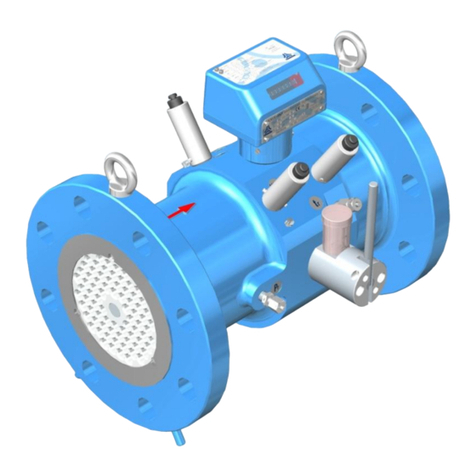
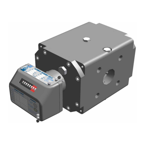
Common CGR-FX User manual

CGR-FX
ROTARY
GAS METERS
OPERATING MANUAL
CGR-FX / OM 16-06
June 2016
PRIOR TO INSTALLATION AND START-UP PLEASE READ
CAREFULLY THESE INSTRUCTIONS

2
CGR-FX / OM 16-06 June 2016
Table of Contents
Page
I. INTENDED USE AND CONDITIONS OF USE 3
II. DESIGN AND FUNCTION 7
III. READOUT DEVICE AND MEASUREMENT OUTPUTS 10
IV. LABELLING AND PROTECTION 15
V. PACKAGING, TRANSPORT AND STORAGE 19
VI. INSTALLATION AND OPERATION 22
VII. OPERATION MONITORING, MAINTENANCE, FAILURES,
REPAIRS 29
VIII. ADDITIONAL EQUIPMENT 31
IX. LIST OF STANDARDS AND TECHNICAL SPECIFICATIONS 37

3
CGR-FX / OM 16-06 June 2016
I. INTENDED USE AND CONDITIONS OF USE
Intended use
Rotary gas meters series CGR-FX are electromechanical pressure devices designed to
measure the volume of gas flowing through a system. The standard version meters may be
used in places with probable occurrence of explosive atmospheres formed as mixtures of
gases with air classified as explosion groups IIA and IIB (and group IIC for the special
versions). Table 1 lists the physical properties of the most common gases and gas mixtures
that may be measured with rotary gas meters.
CGR-FX Rotary Gas Meters enable the gas flows to be measured in any from among four
directions (horizontally –from left to right side, or from right to left side, and vertically –
from top to bottom or from bottom to top).
CGR-FX meters are manufactured with aluminum bodies and with cast iron bodies. Meters
with cast iron bodies may be manufactured as high temperature resistant version ( HTR ),
according to EN 12480:2002, Appendix C.
CGR-FX meters may be optionally equipped with a mechanical output. Mechanical output
may be used to drive peripheral devices. Rotational speed of the output shaft is the same as
the speed of the fastest drum in the index unit. Maximum permissible load torque on the
mechanical output shaft is 0.25 Nm.
As an option the CGR-FX Meters may be equipped with an internal by-pass that opens
automatically if there is a failure of rotors (seizure of rotors). This feature enables the gas
flow to pass by the measuring cartridge.
The rotary gas meters can be used both indoors in stabilized temperature conditions and
outdoors (open location).
Conditions for use
1. Compliance with Directive 2004/22/WE ( MID ) :
-certificate T10569 ( NMI )
- CE marking 1450 ( INiG - Oil and Gas Institute )
- high temperature resistant version (option) HTR pmax = 0.4 MPa
-ambient temperature range –25° C Ta + 70° C
-gas temperature range from –20° C to + 60° C
-storage temperature range from -30o C to + 70o C
-maximum working pressure pmax = 2.0 MPa
-mechanical environment class M2
-electromagnetic environment class E2
-metrological parameters Tables 2A, 2B.
-metrological accuracy class 1.0
-operational position HV,
2. Compliance with Directive 94/9/WE ( ATEX ) :
-certificate KDB 04ATEX034 rev. 5,
-CE marking 1453 ( Central Mining Institute,
Experimental Mine ”Barbara” ).
-operation conditions standard II 2G Ex ia IIB T5 Gb
special II 2G Ex ia IIC T5 Gb
- meter case index of protection IP66/IP67,
- ambient temperature –25° C t + 70° C
Mxx

4
CGR-FX / OM 16-06 June 2016
3. Compliance with Directive 97/23/WE ( PED ) :
-CGR-FX certificate 44065/JN/001/04
-CE marking 1433 ( Office of Technical Inspection )
-compliance with technical specification WUDT/UC/2003.
-maximum calculated pressure for gas meter bodies:
connection PN16 PS = 16 bar,
connection PN20 (ANSI150) PS = 20 bar,
connection PN25 (only cast iron bodies) PS = 25 bar.
- ambient temperature –25° C to + 70° C
4. Compliance with Directive 2004/108/WE (EMC) :
- requirements met by the use of LF and HF pulse emitters (NAMUR) compliant with
the following harmonized standards: EN 60947-5-2:2011, EN 60947-5-6:2000.
Table 1. Physical properties of the most common gases and gas mixtures that may be
measured with CGR-FX. Densities under pressure of 101.325 kPa at 20oC
Gas
or
gas mixture
Chemical
symbol
(formula)
Density
[kg/m3]
Relative
density
w
Gas meter
embodiment
argon
Ar
1.66
1.38
standard IIB
nitrogen
N2
1.16
0.97
standard IIB
butane
C4H10
2.53
2.1
standard IIB
carbon dioxide
CO2
1.84
1.53
standard IIB
ethane
C2H6
1.27
1.06
standard IIB
ethylene
C2H4
1.17
0.98
standard IIB
natural gas
CH4
ca. 0.75
ca. 0.63
standard IIB
helium
He
0.17
0.14
standard IIB
methane
CH4
0.67
0.55
standard IIB
propane
C3H8
1.87
1.56
standard IIB
carbon monoxide
CO
1.16
0.97
standard IIB
acetylene
C2H2
1.09
0.91
special IIC
hydrogen
H2
0.084
0.07
special IIC
air
–
1.20
1
standard IIB
The meter creates pressure drop in the system. The values of the pressure drops is determined
at Qmax (for air at atmospheric conditions, density 0= 1.2 kg/m3) for all CGR gas meter
versions are given in Table 2.
At actual conditions, pressure loss pr[Pa] is calculated according to the formula:
where: w = / 0 –relative gas density (compared to air density) as in Table 1,
pa–atmospheric pressure (pa101 [kPa] ),
p –gauge gas pressure upstream the gas meter [kPa],
Wpd –Pressure drop coefficient determined from Fig. 1
p –pressure drop at Qmax from Table 2 [Pa].
NOTE: Pressure drop in a damaged meter when the by-pass is open, at real conditions, may
be calculated with the above formula. Please replace p from Table 2, column [10] with Bp
·Wpd·p
p
p
p
p
rz
a
a
w

5
CGR-FX / OM 16-06 June 2016
Fig. 1. Pressure drop coefficient as a function of the relative flow Q/Qmax.

6
CGR-FX / OM 16-06 June 2016
Table 2a. Basic metrological parameters of CGR-FX gas meters in aluminium bodies.
DN
Nominal
diameter
G
meter
size.
Qmax
Maxi-
mum
flow.
Qmin
minimum
flow (range)
Qmax / Qmin
(range)
LF
pulse
value
HF
pulse value
(approx)
V
cyclic
volume
∆p
pressure drop at
Qmax
B∆p(3)
at Qmax
Series.
[mm]
[–]
[m3/h]
[m3/h]
[–]
[imp./m3]
[imp./m3]
[dm3]
[Pa]
[kPa]
[–]
1
2
3
4
5
6
7
8
9
10
11
40/50
G10
16
0,8 ÷ 0,16
20 ÷ 100
10/100(2)
15390
0.23
75 / 65
0,15
„171”
40/50
G16
25
1,3 ÷ 0,16
20 ÷ 160
10/100(2)
15390
0.23
160 / 140
0,40
40/50
G16
25
1,3 ÷ 0,16
20 ÷ 160
100(2)
17400
0.31
105/80
0,36
40/50
G16
25
1,3 ÷ 0,16
20 ÷ 160
10
11200
0.31
105/80
0,36
40/50
G25
40
2,0 ÷ 0,16
20 ÷ 250
10/100(2)
15390
0.23
375/280
0,90
40/50
G25
40
2,0 ÷ 0,16
20 ÷ 250
100(2)
17400
0.31
240/180
0,85
40/50
G25
40
2,0 ÷ 0,16
20 ÷ 250
10
11200
0.31
240/180
0,85
40/50
G25
40
2,0 ÷ 0,25
20 ÷ 160
100(2)
11050
0,50
110/80
0,80
40/50
G25
40
2,0 ÷ 0,25
20 ÷ 160
10
7170
0.50
110/80
0,80
40/50/65(1)
G40
65
3,2 ÷ 0,25
20 ÷ 250
100(2)
17400
0.31
340 / 320 / 240
2,10
40/50/65(1)
G40
65
3,2 ÷ 0,25
20 ÷ 250
10
11200
0.31
340 / 320 / 240
2,10
40/50/65(1)
G40
65
3,2 ÷ 0,25
20 ÷ 250
100(2)
11050
0,50
280 / 210 / 150
2,05
40/50/65(1)
G40
65
3,2 ÷ 0,25
20 ÷ 250
10
7170
0.50
280 / 210 / 150
2,05
40/50/65(1)
G40
65
3,2 ÷ 0,40
20 ÷ 160
10
4340
0.81
195 / 150 / 110
2,00
50/65(1)/80
G65
100
5,0 ÷ 0,40
20 ÷ 250
10
7170
0.50
330 / 310 / 320
4,55
50/65(1)/80
G65
100
5,0 ÷ 0,40
20 ÷ 250
10
4340
0.81
325 / 270 / 200
4,50
50/65(1)/80
G65
100
5,0 ÷ 0,65
20 ÷ 160
10
2800
1.24
275 / 225 / 200
4,40
50/65(1)/80
G100
160
8,0 ÷ 0,65
20 ÷ 250
1/10(2)
4340
0.81
650 / 540 / 430
10,5
50/65(1)/80
G100
160
8,0 ÷ 0,65
20 ÷ 250
1/10(2)
2820
1.24
550 / 450 / 395
4,0(4)
80
G160
250
13,0 ÷ 1,0
20 ÷ 250
1/10(2)
2820
1.24
1000
8,5(4)
80/100(1)
G65
100
5,0 ÷ 0,65
20 ÷ 160
10
1630
1.29
115 / 85
1,20
"241"
80/100
G100
160
8,0 ÷ 0,65
20 ÷ 250
1/10(2)
1630
1.29
220 / 190
2,70
80/100
G100
160
8,0 ÷ 1,0
20 ÷ 160
10(2)
1560
2.00
180 / 135
2,60
80/100
G100
160
8,0 ÷ 1,0
20 ÷ 160
1
1080
2.00
180 / 135
2,60
80/100
G160
250
13,0 ÷ 1,0
20 ÷ 250
1/10(2)
1630
1.29
510 / 470
6,30
80/100
G160
250
13,0 ÷ 1,0
20 ÷ 250
10(2)
1560
2.00
370 / 280
6,20
80/100
G160
250
13,0 ÷ 1,0
20 ÷ 250
1
1080
2.00
370 / 280
6,20
80/100
G160
250
13,0 ÷ 1,6
20 ÷ 160
10(2)
1740
3.34
270 / 210
6,00
80/100
G160
250
13,0 ÷ 1,6
20 ÷ 160
1
645
3.34
270 / 210
6,00
80(1)/100
G250
400
20,0 ÷ 1,6
20 ÷ 250
10(2)
1560
2.00
875 / 660
4,2(4)
80(1)/100
G250
400
20,0 ÷ 1,6
20 ÷ 250
1
1080
2.00
875 / 660
4,2(4)
80(1)/100
G250
400
20,0 ÷ 1,6
20 ÷ 250
10(2)
1740
3.34
580 / 460
4,0(4)
80(1)/100
G250
400
20,0 ÷ 1,6
20 ÷ 250
1
645
3.34
580 / 460
4,0(4)
100(1)
G400
650
32,0 ÷ 2,5
20 ÷ 250
10(2)
1740
3.34
1200
9,2(4)
100(1)
G400
650
32,0 ÷ 2,5
20 ÷ 250
1
645
3.34
1200
9,2(4)
(1) –meter versions that are not included in EN12480, Table 7; these meters are acceptable by OIML Recommenda-
tions R137 1&2
(2) –meter version available only with 9-digit counter.
(3) –pressure drop on damaged meter with blocked rotors and open by-pass.

7
CGR-FX / OM 16-06 June 2016
(4) –pressure drop on damaged meter and open double by-pass,
Table 2b. Basic metrological parameters of CGR-FX gas meters in cast iron bodies.
DN
nominal
diameter
G
meter
size
Qmax
maximum
flow
Qmin
minimum
flow
(range)
Qmax / Qmin
(range)
LF
pulse
value
HF
pulse
value
(approx.)
V
cyclic
volume
∆p
pressure drop at
Qmax
B∆p(3)
at Qmax
Series
[mm]
[–]
[m3/h]
[m3/h]
[–]
[imp./m3]
[imp./m3]
[dm3]
[Pa]
[kPa]
[–]
1
2
3
4
5
6
7
8
9
10
11
40/50
G10
16
0,8 ÷ 0,25
20 ÷ 65
100(2)
11050
0.50
33 / 17
0,10
„171”
40/50
G10
16
0,8 ÷ 0,25
20 ÷ 65
10
7170
0.50
33 / 17
0,10
40/50
G16
25
1,3 ÷ 0,25
20 ÷ 100
100(2)
11050
0.50
45 / 35
0,30
40/50
G16
25
1,3 ÷ 0,25
20 ÷ 100
10
7170
0.50
45 / 35
0,30
40/50
G25
40
2,0 ÷ 0,25
20 ÷ 160
100(2)
11050
0.50
110/80
0,80
40/50
G25
40
2,0 ÷ 0,25
20 ÷ 160
10
7170
0.50
110/80
0,80
40/50/65(1)
G40
65
3,2 ÷ 0,25
20 ÷ 250
100(2)
11050
0.50
280 / 210 / 150
2,05
40/50/65(1)
G40
65
3,2 ÷ 0,25
20 ÷ 250
10
7170
0.50
280 / 210 / 150
2,05
40/50/65(1)
G40
65
3,2 ÷ 0,40
20 ÷ 160
10
4340
0.81
195 / 150 / 110
2,00
50/65(1)/80
G65
100
5,0 ÷ 0,40
20 ÷ 250
10
7170
0.50
330 / 310 / 320
4,55
50/65(1)/80
G65
100
5,0 ÷ 0,40
20 ÷ 250
10
4340
0.81
325 / 270 / 200
4,50
50/65(1)/80
G65
100
5,0 ÷ 0,65
20 ÷ 160
10
2800
1.24
275 / 225 / 200
4,40
50/65(1)/80
G100
160
8,0 ÷ 0,65
20 ÷ 250
1/10(2)
4340
0.81
650 / 540 / 430
10,5
50/65(1)/80
G100
160
8,0 ÷ 0,65
20 ÷ 250
1/10(2)
2820
1.24
550 / 450 / 395
4,0(4)
80
G160
250
13,0 ÷ 1,0
20 ÷ 250
1/10(2)
2820
1.24
1000
8,5(4)
80/100
G100
160
8,0 ÷ 1,0
20 ÷ 160
10(2)
1560
2.00
180 / 135
2,60
„241”
80/100
G100
160
8,0 ÷ 1,0
20 ÷ 160
1
1080
2.00
180 / 135
2,60
80/100
G160
250
13,0 ÷ 1,0
20 ÷ 250
10(2)
1560
2.00
370 / 280
6,20
80/100
G160
250
13,0 ÷ 1,0
20 ÷ 250
1
1080
2.00
370 / 280
6,20
80/100
G160
250
13,0 ÷ 1,6
20 ÷ 160
10(2)
1740
3.34
270 / 210
6,00
80/100
G160
250
13,0 ÷ 1,6
20 ÷ 160
1
645
3.34
270 / 210
6,00
80(1)/100
G250
400
20,0 ÷ 1,6
20 ÷ 250
10(2)
1560
2.00
875 / 660
4,2(4)
80(1)/100
G250
400
20,0 ÷ 1,6
20 ÷ 250
1
1080
2.00
875 / 660
4,2(4)
80(1)/100
G250
400
20,0 ÷ 1,6
20 ÷ 250
10(2)
1740
3.34
580 / 460
4,0(4)
80(1)/100
G250
400
20,0 ÷ 1,6
20 ÷ 250
1
645
3.34
580 / 460
4,0(4)
100(1)
G400
650
32,0 ÷ 2,5
20 ÷ 250
10(2)
1740
3.34
1200
9,2(4)
100(1)
G400
650
32,0 ÷ 2,5
20 ÷ 250
1
645
3.34
1200
9,2(4)
(1) –meter versions that are not included in EN12480, Table 7; these meters are acceptable by OIML Rec-
ommendations R137 1&2
(2) –meter version available only with 9-digit counter.
(3) –pressure drop on damaged meter with blocked rotors and open by-pass.
(4) –pressure drop on damaged meter and open double by-pass,
NOTE: Qmin values for a specific meter size may be determined in the range as per Tables 2a and 2b, column 4.
II. DESIGN AND FUNCTION
The rotary gas meter is a volumetric rotary machine based on the principle of proportionality
of the speed of rotation of rotors to the actual volume of gas flowing through the gas meter at
particular pressure and temperature conditions. The gas flowing into the gas meter (Fig. 2)
fills the measurement chamber and the inlet overpressure causes rotation of rotors and
transport of a portion of gas to the gas meter output. The rotational motion of rotors is

8
CGR-FX / OM 16-06 June 2016
transmitted to the counter by means of gears and magnetic clutch. The counter mechanism
totals up the volume flowing through the device, and a revolving counter indicates the total
volume.
Fig. 2. Operation of the rotary gas meter.
The rotary gas meter (Fig. 3) is built of the following basic elements:
Main body. The main body assembly consists of the main body and the front and back
covers. The covers are fixed to the body with screws. The main body is provided with
pressure and temperature measurement taps. The front cover includes a gas-tight partition to
separate the gas chamber from the environment as well as the oil filler plug and oil level
inspection window.
The measurement assembly. The measurement assembly is secured between the main body
covers using elastic sealing inserts. The assembly consists of the measurement chamber with
rotating rotors and two side chambers separated by internal partitions. The rotors are installed
in these covers using roller bearings. Both side chambers contain a reserve supply of oil for
lubrication of bearings and gears of the measurement system. Lubrication is achieved by
means of oil spray generated by blades installed on rotor shafts.
The measurement assembly may be provided with automatic by-pass which opens if a
failure of meter occurs (blockage of rotors). If so gas flow may omit the measuring cartridge.
The meter failure (opened by-pass) is signaled by the control circuit that sends an appropriate
signal to an external device.
This is an optional solution.
Drive transmission assembly. The drive transmission assembly is installed in the front cover
and transmits the rotary motion of the rotors from the measurement assembly to the counter
through a gas-tight partition. The assembly consists of a cog gear and a magnetic clutch. The
driven part of the clutch may be complete with an inducer for the high frequency emitter.
The counter assembly. The counter assembly further reduces the rotational speed (by means
of a worm gear and cylindrical gears) to drive the mechanical counter and the elements that
induce the low frequency electric signal emitters. The assembly is also complete with sockets
for transmitting the low and high frequency electric signals outside the gas meter. As an
option the index head may be provided with mechanical drive shaft.

9
CGR-FX / OM 16-06 June 2016
Fig. 3. Cross-section of the rotary gas meters CGR-FX

10
CGR-FX / OM 16-06 June 2016
III. READOUT DEVICE AND MEASUREMENT OUTPUTS
The gas meters CGR-FX are equipped with a readout device in the form of a mechanical
counter and electric signal outputs.
The index head may be provided with:
- mechanical output (drive shaft),
- replaceable HF pulse sensor installed in the index head support,
The meter housing is provided with pressure and temperature measurement taps (options).
The outputs allow to monitor the gas meter operation and to connect the external equipment.
Fig. 4 shows the location of the measurement outputs on the gas meter.
Fig. 4. Location of measurement outputs of the CGR-FX gas meters.
The mechanical counter is located inside the counter assembly and visible through a
polycarbonate inspection window. The counter allows direct readout of the actual volume of
gas that has flown through the gas meter under particular pressure and temperature conditions.
The counter assembly may be rotated around the horizontal axis of the gas meter in a range of
ca. 350o, allowing for convenient readout of the counter from virtually all directions.

11
CGR-FX / OM 16-06 June 2016
Electric signal outputs. There are two possible types of electric signal outputs: low
frequency (LF) outputs and high frequency (HF) outputs. The counter may be equipped with
the maximum of two sockets and six electric pulse emitters. The pulse emitters are:
-one or two inductive high frequency emitters HF,
-one or two inductive low frequency emitters LFI,
-one or two low frequency reed contact emitters LFK,
-one low frequency emitter LFW equipped with Wiegand sensor,
-one control circuit utilising normally closed reed relay switch AFK.
The reed relay emitters LFK and LFW are designed to work with a battery-powered or
grid/battery-powered data logger and volume converter located in the vicinity of the gas meter
(up to ca. 2 m). The induction emitters, both of the LFI and the HF type, may emit electric
current signals over significantly longer distances (up to ca. 200 m, depending on conditions).
Due to high power consumption, they are designed to work only with grid-powered volume
converters. Gas volumes corresponding to individual pulses of the LF emitter are presented in
Table 2. The number of HF pulses per one square meter of gas is determined individually for
each gas meter and listed on the type plate. The approximate value of the HF emitter constant
is given in Table 2. The HF output is particularly useful for tracking changes in the flux of the
gas flowing through the gas meter.
All emitters located in the gas meter counter assembly are connected to Amphenol-Tuchel
C091 31N006 100 2 sockets located in the back wall of the counter case. Cords connected to
sockets should be equipped with Amphenol-Tuchel C091 31H006 100 2 plugs. Amphenol-
Tuchel connections in CGR gas meters are in the IP67 protection class. Table 3 presents
potential connections of emitters to individual electric signal output sockets.
Table 3. Potential connections of gas meter emitters to electrical output sockets.
Pin
Polarity
LFK 1
or
LFW 1
LFK 2
or
LFW 2
AFK
(*)
LFI 1
(*)
LFI 2
HF 1
HF 2
Socket 1
1
S
O
4
+
S
O
2
O
P
P
O
O
5
+
O
P
P
O
O
3
O
P
6
+
O
P
Socket 2
1
P
O
4
+
P
O
2
O
O
O
P
O
5
+
O
O
O
P
O
3
O
P
6
+
O
P
S –standard connections, P –preferred connections, O –optional connections
Sockets 1 and 2 with pin numbering are shown in Fig. 8a and 8b.
Standard versions of the CGR-FX gas meter features one
low frequency reed contact emitter LFK 1
One of the inductive emitters installed in the counter may act as a control element in the gas
meter. If the counter is not equipped with a HF emitter, an external control element may be
connected to the gas meter for testing purposes (see section VII). Inductive HF emitter type
CHFI-04 by Common S.A. should be used as the external control element. The type plate of
the gas meter includes the value of the constant for emitters HF1 and HF2; this value is also

12
CGR-FX / OM 16-06 June 2016
valid for the external control element emitter. After disconnecting the control element, the
socket is tightly plugged and sealed (Fig. 9).
In line with the conditions for use, the CGR-FX gas meters should be equipped with emitters
allowing for at least II 2G Ex ib IIC T5 Gb protection. This condition is satisfied for
instance by the following emitters used in the counter:
-HF type Bi1-EG05-Y1(1) by Hans Turck GmbH II 1G Ex ia IIC T6
-LFI type Si5-K09-Y1(1) by Hans Turck GmbH II 1G Ex ia IIC T6
-LFK type CLFK-03 by Common S.A.
-LFW type CLFW-01 by Common S.A.
-LFW type CLFW-02 by Common S.A.
(1) –required linear characteristics of the emitter power circuit.
Acceptable intrinsic safety parameters
Bi1-EG05-Y1
Si5-K09-Y1
CLFK-03
CLFW-01
CLFW-02
Ui= 20 V DC
Ui= 20 V DC
Ui= 15.5 V DC
Ui= 30 V DC
Ii= 60 mA
Ii= 60 mA
Ii= 52 mA
Ii= 52 mA
Pi= 200 mW
Pi= 130 mW
Pi = 169 mW
Pi = 0.6 W
Li= 150 μH
Li= 350 μH
Li≈ 0
Li≈ 0
Ci= 150 nF
Ci= 250 nF
Ci≈ 0
Ci≈ 0
ATTENTION!
The total voltage of separate galvanic intrinsically safe circuits connected
to one connector must comply with: Ui1 + Ui2 ≤ 30 V
Intrinsic safety parameters of the emitters installed in the gas meter are listed in the type plate.
The intrinsic safety requirements are met by the following emitters:
- HF type CHFI-04 (1) by Common S.A. II 2G Ex ia IIC T6.
-LFK type CLFK-04 by Common S.A.
-LFW type CLFW-04 by Common S.A.
(1) - required linear characteristics of the emitter power circuit.
Acceptable intrinsic safety parameters
CHFI-04
CLFK-04
CLFW-04
Ui= 20 V DC
Ui= 15.5 V DC
Ui= 30 V DC
Ii= 60 mA
Ii= 52 mA
Ii= 52 mA
Pi= 200 mW
Pi = 169 mW
Pi = 0.6 W
Li= 150 μH
Li≈ 0
Li≈ 0
Ci= 150 nF
Ci≈ 0
Ci≈ 0
NOTICE!
Intrinsic safety parameters are electrical parameters determined during analysis of the
device construction. Their values are determined for the most unfavorable operating condi-
tions or a failure of the device. Values of these parameters are limited to safe levels of spe-
cific gas mixture. They are not to be regarded as rated working parameters of the device
operation.

13
CGR-FX / OM 16-06 June 2016
Compatibility of intrinsic safety parameters of external connected devices are present-
ed in the Table below.
Compatibility conditions for intrinsic safety parameters
External device
Condition
Gas meter
Output voltage
Uo
Ui
Input voltage
Output current
Io
Ii
Input current
Output power
Po
Pi
Input power
Maximum external capacitance
Co
Co Ci+Ck
Ci
Internal capacitance
Maximum external inductivity
Lo
Lo Li+Lk
Li
Internal inductivity
As regards the cable parameters (Ck), (Lk) the following shall be presumed:
The most unfavourable parameters declared by the cable manufacturer.
Parameters measured in accordance with EN 60079-14. or 200pF/m and 1H/m,
or 30H/,where the connection contains two or three leads (with or without
screen).
Nominal operating parameters of the emitters:
LFK (reed contact) and LFW (Wiegand) [open collector emitters]
CLFK-03 / CLFK-04 / CLFW-01 / CLFW-02 / CLFW-04
closed switch resistance Rz= 100÷ 2 k
open switch resistance Ro> 100 M
max. switching frequency fp= 2 Hz
Inductive proximity emitters –NAMUR standard
Si5-K09-Y1 Bi1-EG05-Y1 / CHFI-04
max. switching frequency fp= 2 Hz fp= 0.5 kHz
rated operating voltage Un = 8,2V
rated current of non-activated switch I >= 2,1mA
rated current of activated switch I <= 1,2mA
The remaining nominal operating parameters of the emitters used in the gas meters are in line
with the requirements of the PN-EN 60947-5-6:2002 standard.
Please observe the polarity when making connections to external devices. It is not re-
quired in case of LFK and AFK emitters only.
Temperature measurement output.
The rotary gas meters CGR-FX allows temperature measurements only when delivered as a
special order version; temperature measurements are not available in the standard version.
Temperature probes are not a part of the meter with the temperature tapping and it is
necessary to order them separately.
Temperature measurement outputs may be located on both sides of the main body (Fig. 4).
The temperature measurement taps may be fitted with thermowell(s) (Fig. 5); with the length
of L=110 mm for the bodies of the “171” series and L=120 mm for the bodies of the “241”
series. It is recommended to fill the thermowell with silicon oil prior to installation of
temperature probe. Temperature taps which are not used are plugged with ¼” NPT plugs.

14
CGR-FX / OM 16-06 June 2016
a) Thermowell b) Thermowell with temperature probe
Fig. 5 Thermowells
Pressure measurement output.
Pressure measurement outputs (pressure measurement taps) are located at both sides of the
main body (Fig. 4). Openings are provided with ¼” NPT thread (Fig. 6).
a.) b.)
Fig. 6. ¼” NPT pressure measurement tap
The outputs are used to connect pressure transducers, either directly to the socket (Fig. 6b) or
via three-way valves. Outputs that are not in use are blinded with plugs (Fig. 6a). Both plugs
and sockets may be protected by installation seals.

15
CGR-FX / OM 16-06 June 2016
Mechanical counter output (option)
The gas meter may be optionally equipped with a mechanical output. The mechanical output
may be used to drive external, removable devices connected to the gas meter counter. A
paddled tip of the counter shaft is located on the right side of the counter and covered by a
protective cap. The rotational speed of the shaft is identical to the speed of the fastest counter
barrel. The shaft rotates in counter-clockwise direction; the direction is marked on the plate
(Fig. 7b) fixed at the mechanical output cover. The values of the maximum acceptable
allowable momentum of the mechanical output shaft tip Mmax = 0,25 [Nmm] and the constant
corresponding to one complete turn of the drive shaft, 1 tr = …… [m3] are also given on the
plate
Fig. 7a Mechanical output drive shaft
Fig. 7b Mechanical output type plate
IV. LABELLING AND PROTECTION
Information on the basic technical parameters of the gas meter along with the serial number
and manufacture year is listed on rating plates (Figs. 8a, 8b and 8c) fixed to the counter
casing.
Fig. 8a. Type plates –special version HTR

16
CGR-FX / OM 16-06 June 2016
Fig. 8b. Type plates –standard version for IIA and IIB explosion groups
Fig. 8c. Type plates –special version for IIC explosion group

17
CGR-FX / OM 16-06 June 2016
The top of the gas meter body features signs informing about the direction of gas flow and the
locations of pressure and temperature measurement outputs (Fig. 4).
Following verification by the authorized manufacturer laboratory, each gas meter is protected
with seals placed in locations shown in Fig.9. On customer’s request the gas meter may be
delivered along with the calibration certificate.
Fig. 9. Locations of seals on CGR-FX rotary gas meter.

18
CGR-FX / OM 16-06 June 2016
Fig. 10a Initial verification seal (sample) Fig. 10b Sample of protective sticker
Re-calibration period depends on metrological regulations in the country where the meter has
been installed. Before the end of the verification period, the gas meter should be submitted for
secondary verification in an authorized laboratory.
Re-calibration of meters may be performed by COMMON S.A., in our own laboratory. It is
also possible to make necessary adjustments and repairs, if required.
Retaining the verification stamp seal is required for the gas meter to be considered
a legal measurement device.
V. PACKAGING, TRANSPORT AND STORAGE
The gas meter is supplied in factory-made packaging which provides appropriate protection
during transport and storage (Figs 11a and 11b). The packaging consists of reinforced
cardboard box and profiled cardboard inserts. Appropriate information regarding the contents
and restrictions regarding gas meter loading/unloading and transport is printed on the
packaging. Side walls of the box feature handle holes for transporting the gas meter. Gas
meters submitted for repair or renewed legal approval should be sent in factory-made
packaging or other packaging providing at least equal protection during transport.
Every rotary gas meter produced by Common S.A. is supplied with the following:
-a 6-pin Amphenol-Tuchel C091 31H006 100 2 plug to be used for connecting a
converter or data logger to the low frequency electric signal output;
-a bottle of oil for gas meter lubrication;
-a set of elements for fixing the gas meter in the installation: hexagonal flat end
M16x70 set screws compliant with the PN-EN ISO 4026:2004 standard, washers
and nuts;
-the technical manual.
The rotary gas meter is a high precision measurement device
and should be handled with appropriate caution.
Following principles should be observed during transport and storage of the gas meters:
K4

19
CGR-FX / OM 16-06 June 2016
1. Gas meters should not be thrown, turned over or subjected to strong impacts (e.g. during
fast transport using carts without springs).
2. It is not allowed to lift the meter by the index head.
3. Factory-placed covers or other shields of gas meter should not be removed until directly
before installation.
4. The storage site should protect the gas meter from atmospheric precipitation and moisture.
5. Care should be taken of the seals placed on the gas meter. Damage of seals may lead to
warranty voidance and legal consequences as regards the clearance of accounts
between the gas supplier and the customer.
6. It is not required for the gas meter to be primed with oil during warehouse storage.

20
CGR-FX / OM 16-06 June 2016
Fig. 11a. Packaging of the CGR-FX gas meters (aluminum bodies)
This manual suits for next models
1
Table of contents
Other Common Measuring Instrument manuals
Popular Measuring Instrument manuals by other brands

PCB Piezotronics
PCB Piezotronics IMI SENSORS 604B61/-0003 Installation and operating manual

HT
HT HT78 user manual

HAWEKA
HAWEKA BikeBoss operating instructions

Electron Microscopy Sciences
Electron Microscopy Sciences 72907-01 Instructional manual

HyQuest Solutions
HyQuest Solutions TB3 instruction manual

DeFelsko
DeFelsko PosiTector DPM quick guide