Nuvoton NAU83P20 User manual

Daughter Board
NO.:
VERSION:
1.0
PAGE:
1
1
NAU83P20 Daughter Board
Setup
1Introduction.............................................................................................2
2Overview .................................................................................................3
2.1 NAU83P20 Daughter Board Overview...................................................3
2.1.1 Power Down Button......................................................................3

Daughter Board
NO.:
VERSION:
1.0
PAGE:
2
2
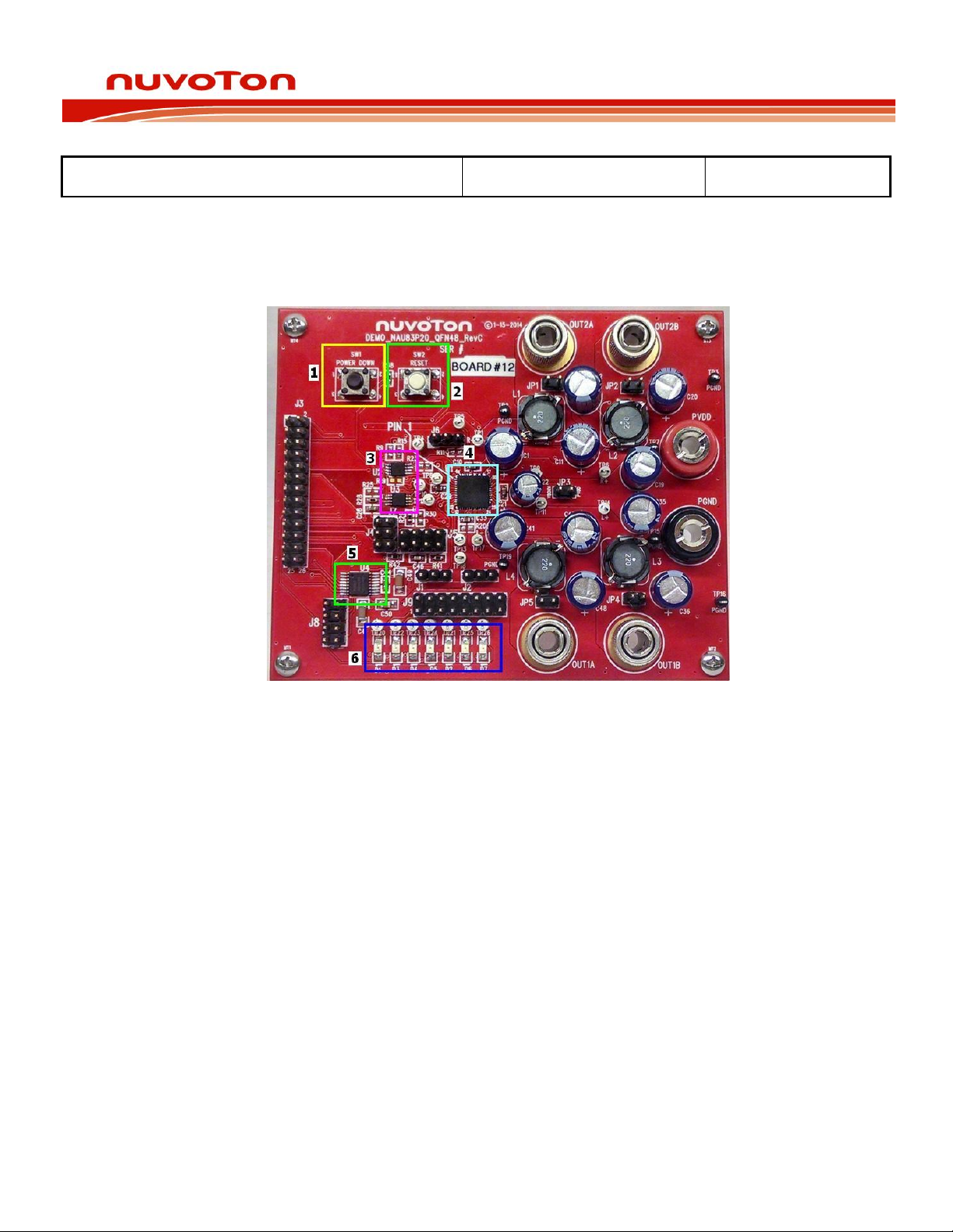
2.1.2 Reset Button ................................................................................3
2.1.3 NAU82011 (x2).............................................................................3
2.1.4 NAU83P20....................................................................................3
2.1.5 NAU8402 .....................................................................................4
2.1.6 LED Warning Lights ......................................................................4
2.2 Connectors and Jumpers .....................................................................4
2.2.1 Master Board Connector (J1) .........................................................4
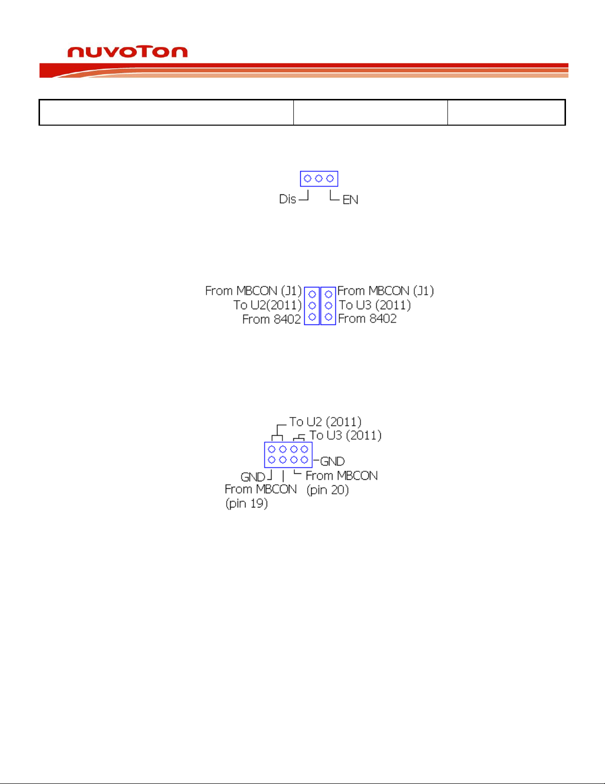
2.2.2 Slew Control (J2) ..........................................................................5
2.2.3 Positive Audio Input (J3/J4) ..........................................................5
2.2.4 Negative Audio Input (J5) .............................................................5
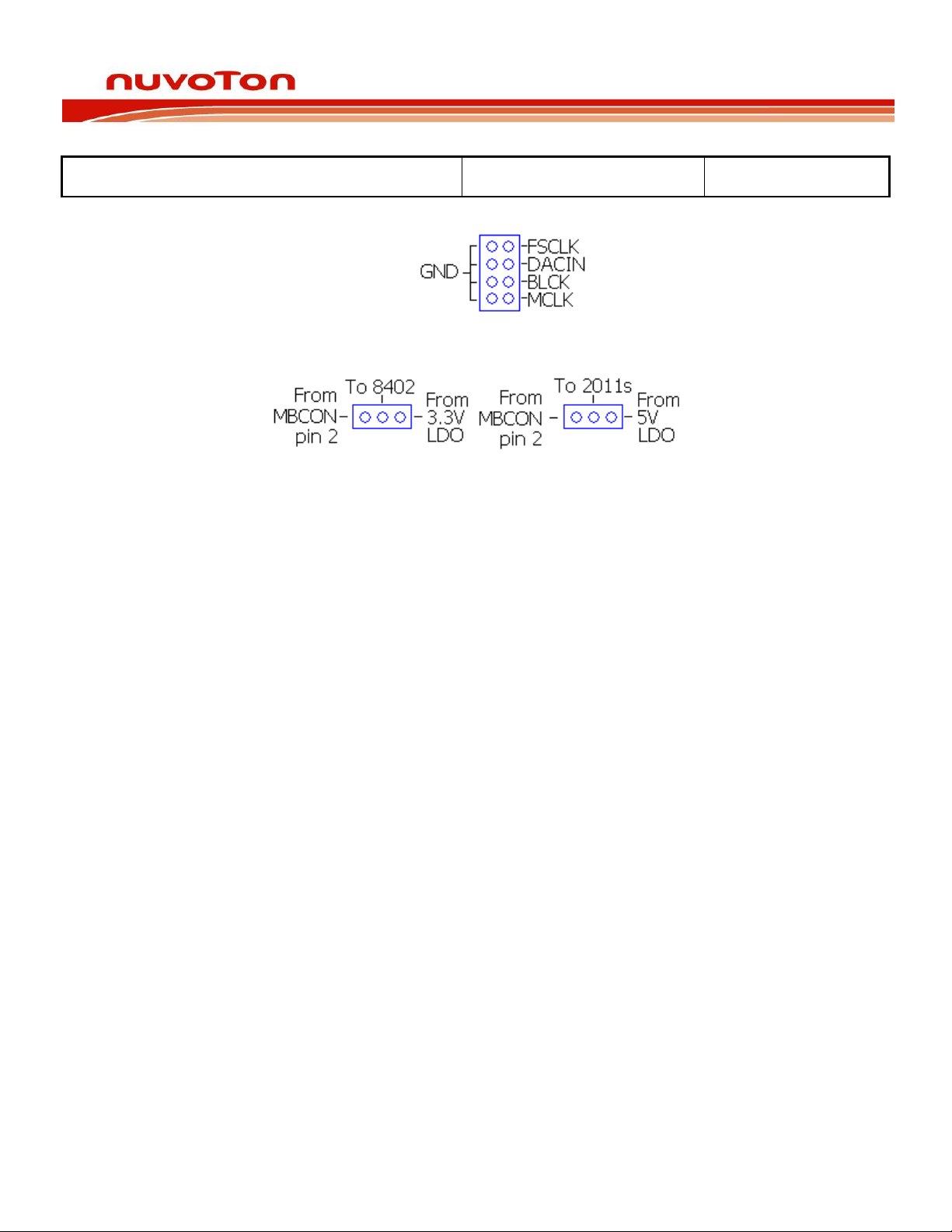
2.2.5 Audio Precision Header for NAU8402 (J6).......................................5
2.2.6 NAU82011 and NAU8402 Power Select Jumpers (J7/J8)..................6
2.2.7 Fault Signal to Power Down Jumper (J9)........................................6
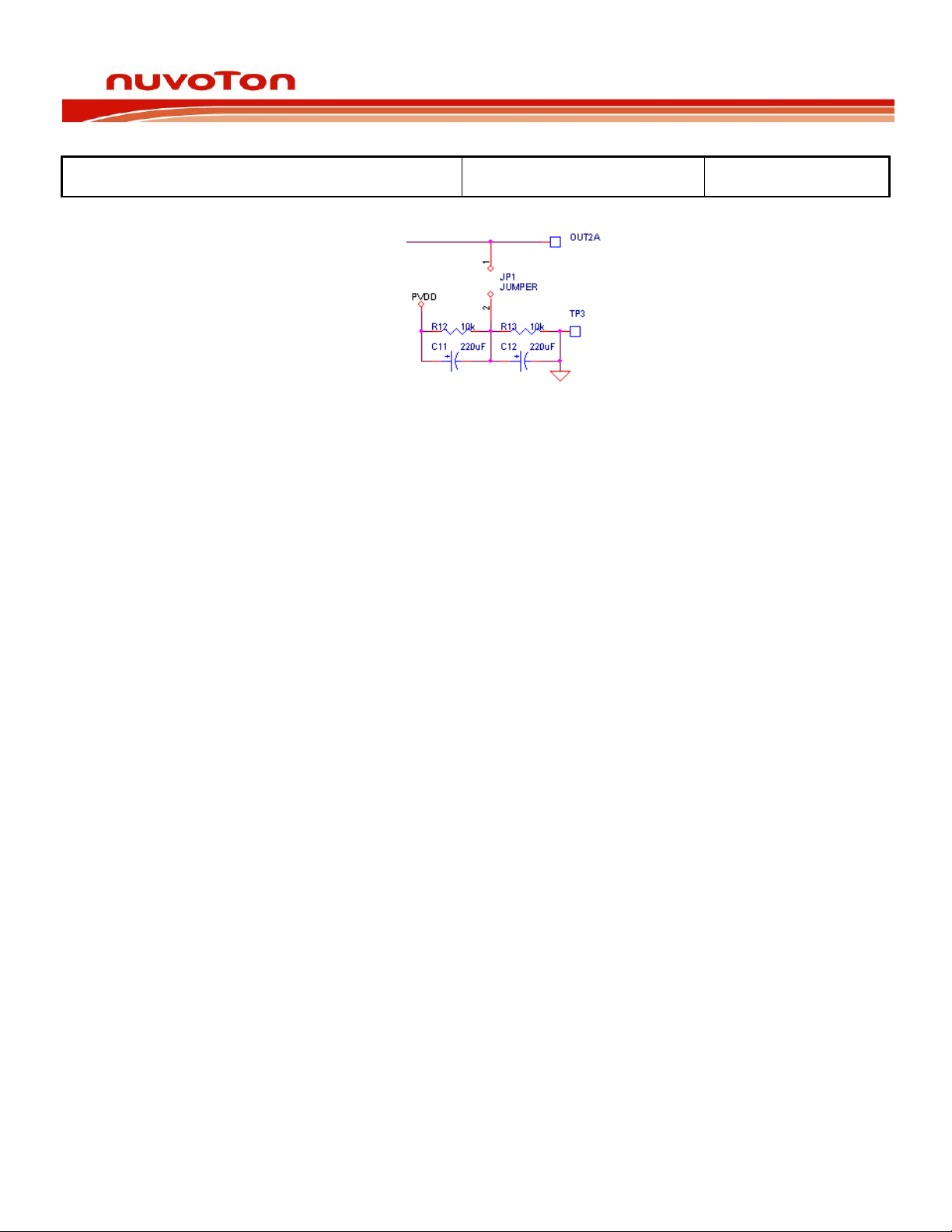
2.2.8 Audio Outputs after LRC Filter .......................................................6
2.2.9 Output Capacitor Bypass Jumpers..................................................6
2.2.10 VDD High Voltage Connection ....................................................7
2.2.11 Power Inputs (7V-25V) ..............................................................7
3Setup ......................................................................................................8
3.1 AUX Input from Nuvoton Power Audio Master Board .............................8
3.2 I2S Input from Nuvoton Power Audio Master Board ..............................9
3.3 Standalone Operation .......................................................................10
1Introduction
The NAU83P20 Daughter Board is designed to be used either standalone or
while attached to the Nuvoton Power Audio Master Board. This document will
cover the setup of the NAU83P20 Daughter Board with and without the
Nuvoton Power Audio Master Board attached.

Daughter Board
NO.:
VERSION:
1.0
PAGE:
3
3
2Overview
2.1 NAU83P20 Daughter Board Overview
2.1.1 Power Down Button
While depressed the NAU83P20 will enter into a low power mode, all
outputs will be disabled and all inputs will enter into a high impedance
state. When the power down button is released the NAU83P20 will resume
normal operation.
2.1.2 Reset Button
When pressed the faults of the NAU83P20 will be reset into their power up
state.
2.1.3 NAU82011 (x2)
The NAU82011 is a 3W Class D audio amplifier, these provide the Class D
input signal required by the NAU83P20.
2.1.4 NAU83P20
The NAU32P20 is a 20W Class D audio amplifier and is the chip featured
on the evaluation board.

Daughter Board
NO.:
VERSION:
1.0
PAGE:
4
4
2.1.5 NAU8402
The NAU8402 is a digital to analog converter that will take a digital input
from the Nuvoton Power Audio Master Board and convert it into an analog
signal that is fed to the NAU82011’s.
2.1.6 LED Warning Lights
The LED warning lights will become illuminated if the chip detects any of
the following faults: Fault (D1), Over Current (D3), Under Voltage (D4),
Temperature Warning (D5), Over Temperature (D2), Shutdown (D6), and
Over Current Latch (D7). Full descriptions of these faults can be found in
the data sheet.
2.2 Connectors and Jumpers
2.2.1 Master Board Connector (J3)
This male connector will be plugged into the matching female connector
on the underside of the Nuvoton Power Audio Master Board.
See Master
Board guide for pin out.

Daughter Board
NO.:
VERSION:
1.0
PAGE:
5
5
2.2.2 Slew Control (J6)
A jumper placed between pins 1-2 will disable the slew control and a
jumper placed between pins 2-3 will enable the slew control.
Slew enabled
is recommended.
2.2.3 Positive Audio Input (J4/J7)
If the jumpers are placed in the upper position the positive audio input
will be fed from the Nuvoton Power Audio Master Board to the
NAU82011’s. In the lower position the positive audio input will be taken
from the NAU8402.
2.2.4 Negative Audio Input (J5)
If the jumpers are placed in the center positions the negative audio input
will be fed from the Nuvoton Power Audio Master Board to the
NAU82011’s. In the outer positions the negative audio inputs will be
grounded allowing for single ended use from the Nuvoton Power Audio
Master Board or the NAU8402.
2.2.5 Audio Precision Header for NAU8402 (J8)
This jumper was provided so that the user can monitor the inputs from
the master board or provide an external input in the case that the
Nuvoton Power Audio Master Board was not in use.

Daughter Board
NO.:
VERSION:
1.0
PAGE:
6
6
2.2.6 NAU82011 and NAU8402 Power Select Jumpers (J1/J2)
These jumpers allow the power source of the NAU82011’s and the
NAU8402 to be selected. In the left position the power will come from the
Nuvoton Power Audio Master Board in the right position the power will
come from the NAU83P20’s onboard LDOs. Please note that while the
NAU82011s can run between 2.5V and 5.5V the NAU8402 can only
operate between 3V and 3.6V.
It is recommended to use the LDO
whenever possible.
2.2.7 Fault Signal to Power Down Jumper (J9)
This jumper can be used to connect any of the fault signals directly to the
power down pin, forcing the chip into power down whenever the selected
fault is detected. Pins are matched with the LED order listed in section
2.1.6 in this document.
It is recommended to connect the Shutdown Latch
(D7), pins 13-14, while in use.
2.2.8 Audio Outputs after LRC Filter (OUT1A/OUT1B/OUT2A/OUT2B)
Audio output banana plugs for speakers or audio testing, these outputs
are after the onboard LRC filter.
2.2.9 Speaker Plugs for Single Ended Operation (JP1/JP2/JP4/JP5)
The left sides of these jumpers connect to the filtered output of the
NAU83P20 for the positive side of the speaker. The right side connects to
a voltage divider and capacitor network that provides a PVDD/2 reference
for the negative side of the speaker during single-ended operation. This is
included to prevent an overcurrent condition.

Daughter Board
NO.:
VERSION:
1.0
PAGE:
7
7
2.2.10 VDD High Voltage Connection
This jumper connects the PVDD1/2 (NAU83P20 Class D drivers) Pins to
the VDDHV (NAU83P20 Circuitry) Pin. If this jumper is not in place an
external power supply need to be connected to the VDDHV side of the
jumper so that the chip’s internal circuitry can function.
2.2.11 Power Input (7V-25V)
Banana jacks to provide power and ground to the board if it is not
provided by the Nuvoton Power Audio Master Board.

Daughter Board
NO.:
VERSION:
1.0
PAGE:
8
8
3Setup
3.1 AUX Input from Nuvoton Power Audio Master Board
3.1.1 Attach Master Board to Daughter Board
3.1.2 Setup Master Board
3.1.2.1 Apply 5V to Master Board (MBVCC/MBGND)
3.1.2.2 Select Desired NAU82011 Voltage using DBVDD Select (E1)
3.1.2.3 Select AUX Input using a jumper on SDIN1 (E2) and SDIN2 (E3) to connect
pins 3-5
3.1.2.4 Select SDIN1 and SDIN2 pass-through using a jumper to connect pins 1-2
3.1.2.5 Apply 7V-25V to PVCC (PVCC/PGND)
3.1.2.6 Attach Audio Inputs to RCA Input Jacks (RJ1/RJ2)
3.1.3 Setup Daughter Board
3.1.3.1 Select Desired Slew Control (J6), section 2.2.2
3.1.3.2 Place Positive Audio Input Jumpers to take signal from the Nuvoton Power Audio
Master Board (J4/J7), section 2.2.3
3.1.3.3 Select Differential or Single Ended Operation Using the Negative Audio Input
Jumper (J5), section 2.2.4
3.1.3.4 Select Desired Power Input Source to the NAU82011s (J2), section 2.2.6
3.1.3.5 Power Input to the NAU8402 (J1) should be left open as it is not in use, section
2.2.6
3.1.4 GUI
3.1.4.1 Select NAU83P20 in the Chip Select drop down menu
3.1.4.2 Enable the NAU82011s
3.1.4.3 Ensure the NAU83P20 is powered up and not in Power Down or Mute states

Daughter Board
NO.:
VERSION:
1.0
PAGE:
9
9
3.2 I2S Input from Nuvoton Power Audio Master Board
3.2.1 Attach Master Board to Daughter Board
3.2.2 Setup Master Board
3.2.2.1 Apply 5V to Master Board (MBVCC/MBGND)
3.2.2.2 Select 3.3V using DBVDD Select (E1)
3.2.2.3 Select Desired Input, SPDIF or ADC, using SDIN1 (E2) and SDIN2 (E3)
3.2.2.4 Select MCLK, SDIN1, SDIN2, BCLK and FSCLK pass through using I2S selection
jumpers in the left position
3.2.2.5 Apply 7V-25V to PVCC (PVCC/PGND)
3.2.2.6 Attach Audio Inputs to RCA Input Jacks (RJ1/RJ2) or SPDIF input to RCA jack
(J1) or Optical input jack (U3)
3.2.3 Setup Daughter Board
3.2.3.1 Select Desired Slew Control (J2), section 2.2.2
3.2.3.2 Place Positive Audio Input Jumpers to take signal from the NAU8402 (J4/J7),
section 2.2.3
3.2.3.3 Select single ended input using Negative Audio Input Jumper (J5), section 2.2.4
3.2.3.4 Select Desired Power Input Source to the NAU82011s and NAU8402 (J8/J7),
section 2.2.6
3.2.4 GUI
3.2.4.1 Select NAU83P20 in the Chip Select drop down menu
3.2.4.2 Enable the NAU82011s
3.2.4.3 Enable the NAU8402
3.2.4.4 Ensure the NAU83P20 is powered up and not in Power Down or Mute states

Daughter Board
NO.:
VERSION:
1.0
PAGE:
10
10
3.3 Standalone Operation
3.3.1 Use Master Board Connector (J3) to apply the connections pictured below:
3.3.2 Select Desired Slew Control (J6), section 2.2.2
3.3.3 Place Positive Audio Input Jumpers to take signal from the Nuvoton Power Audio
Master Board (J4/J7), section 2.2.3
3.3.4 Select Differential or Single Ended Operation Using the Negative Audio Input
Jumper (J5), section 2.2.4
3.3.5 Select Desired Power Input Source to the NAU82011s (J2), section 2.2.6 If using an
external supply to power the NAU82011s it should be connected to pin 2 of J3.
3.3.6 Power Input to the NAU8402 (J1) should be left open as it is not in use, section
2.2.6
3.3.7 Apply Power to banana jacks (PVDD/PGND), 7V-25V
Table of contents
Other Nuvoton Computer Accessories manuals
Popular Computer Accessories manuals by other brands

Corsair
Corsair CC650DW quick start guide

Silvercrest
Silvercrest MTS 2218 User manual and service information

Tripp Lite
Tripp Lite SEC4002RF Specification sheet

Corsair
Corsair Carbide series manual

Corsair
Corsair Carbide series installation guide

DigiDesign
DigiDesign Pro Tools 24 MIX Expanded Systems Guide