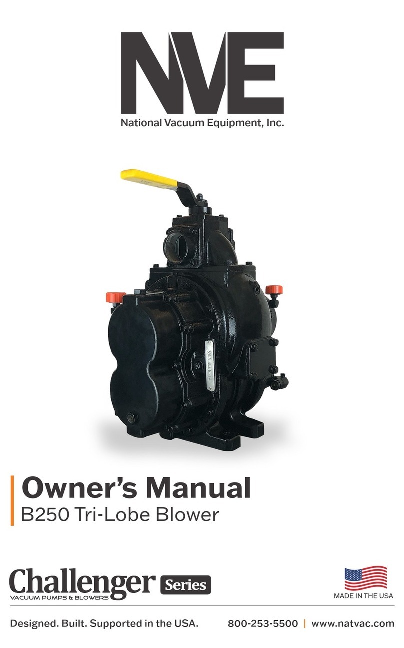
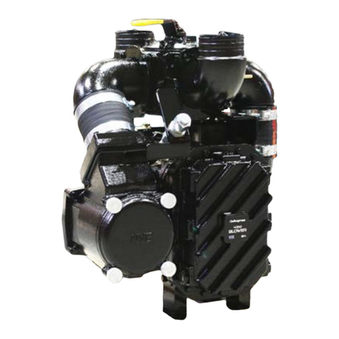
NVE 4307 Series System manual

National Vacuum Equipment
Owner’s Manual
&
Operating Instructions
Models 4307 & 4310 Blower
MADE
IN USA
Visit our web site to download pump setup guides,
brochures and other technical information.

2 | 4307 & 4310 Blower natvac.com | 800.253.5500
© 2013 National Vacuum Equipment, Inc.
1212 R/5
No part of this manual may be reproduced without the written permission of
National Vacuum Equipment, Inc.
4307 & 4310 Blowers
Owner’s Record
Date of Purchase: _________________________
Purchased from: __________________________
Serial Number: ____________________________

4307 & 4310 Blower | 3natvac.com | 800.253.5500
Table of Contents
5
5
Limited Warranty
6
7
Overview
8
8
9
9
9
10
11
11
11
12
Storage
13
13
13
14
14
15
15
16
16
16
16

4 | 4307 & 4310 Blower natvac.com | 800.253.5500
17
17
17
17
18
18
18
18
18
18
19
19
20
20
20
Maintenance
21
22
22
22
23
23
23
24
26
27
28
30
34
36

4307 & 4310 Blower | 5natvac.com | 800.253.5500
Introduction
About National Vacuum Equipment, Inc.
-
Our History
-
-
-

6 | 4307 & 4310 Blower natvac.com | 800.253.5500
Limited Warranty
Warranty
-

4307 & 4310 Blower | 7natvac.com | 800.253.5500
Warranty Procedures

8 | 4307 & 4310 Blower natvac.com | 800.253.5500
Overview
General Blower Operation
General Blower Construction
BALLAST INJECTION
BALLAST INJECTION
INTAKE
EXHAUST
BLOWER HOUSING
DRIVE ENDPLATE
NON-DRIVE ENDPLATE
DRIVE OIL
TANK
DRIVE ROTOR
IDLER ROTOR
DRIVE BEARINGS NON-DRIVE BEARINGS
OIL SLINGER
OIL SLINGER
TIMING GEARS
SEAL SLEEVE
SEAL RINGS
SEAL VENT

4307 & 4310 Blower | 9natvac.com | 800.253.5500
Sereial Number
Location of Serial Number
Operating Environment
-
Operating Limits

10 | 4307 & 4310 Blower natvac.com | 800.253.5500
Performance (Reference Only)
Vacuum (Inches of Mercury) Pressure (PSI)
RPM 0 9 15 18 21 24 27 510 15 18
2000 HP 2.0 7.4 11.0 12.8 14.6 16.4 - 8.1 14.2 20.3 24.0
CFM 280 171 114 77 26 - - 183 143 113 97
2500 HP 2.5 9.2 13.7 16.0 18.2 20.5 - 10.1 17.7 25.4 29.9
CFM 349 241 184 147 96 17 - 253 213 183 167
3000 HP 3.0 11.1 16.5 19.2 21.9 24.6 27.3 12.1 21.3 30.4 35.9
CFM 419 311 254 217 166 87 - 323 283 253.0 237.0
3500 HP 3.5 12.9 19.2 22.4 25.5 28.7 31.8 14.2 24.8 35.5 41.9
CFM 489 381 324 286 236 157 - 393 353 322.0 307.0
4000 HP 4.0 14.8 22.0 25.6 29.2 32.8 36.4 16.2 28.4 40.6 47.9
CFM 559 451 394 356 306 227 57 463 423 392 376
When installing a NVE 4307 blower we recommend a normal R.P.M. range from 2700 to 4000. Other speeds are o.k. as long as
exhaust gas temperatures read on the supplied thermometer do not exceed 290 degrees F over ambient temperature.
4307
0 18 24 27 10
2 17.8 23.1 - 24.8
500 407 255 - 324
4 35.6 46.1 51.4 39.7
826 661 528 182 631
4.5 40 51.9 57.8 44.7
931 763 660 270 733
RPM
2400 Hp.
CFM
Pressure (PSI)Inches of Vacuum (Hg)
4000
4500 Hp.
CFM
Hp.
CFM
Maximum 4500 RPM Intermittent Operation Only.
The maximum allowable operating
vacuum will vary depending on R.P.M.,
ambient temperature, altitude and
time running. The basic principle to
keep in mind is - faster R.P.M., higher
air temperature and longer run time all
equal more heat in the pump. When
installing an NVE 4310 blower we
recommend a normal R.P.M. of 4000.
Other speeds are o.k. as long as exhaust
gas temperatures read on the supplied
thermometer do not exceed 375
degrees F.
4310

4307 & 4310 Blower | 11natvac.com | 800.253.5500
Dimensions
Air Flow Control
Sound Level
131-4310-LDB
CW ROTATION
SCALE 1 / 4
131-4310-LSB
CCW ROTATION
SCALE 1 / 4
DIMENSIONS SYMMETRICAL TO LDB BLOWER
DETAIL C
SCALE 1 / 2
1
1
2
2
3
3
4
4
5
5
6
6
7
7
8
8
A A
B B
C C
D D
NVE National
Vacuum
Equipment, Inc.
2670 Aero Park Drive, Traverse City, MI 49686
Phone: (231) 941-0215 Fax: (231) 941-2354
TOLERANCES UNLESS OTHER WISE SPECIFIED
One place (.X) ±.1
Two places (.XX) ±.01
Three places (.XXX) ±.005
Angles ±1°
All machined surfaces 125 RMS max.
Remove all burrs and sharp edges.
CAD drawing - NO manual changes.
All dimensions in inches unless specified.
This document may contain confidential trade
secret information which is the exclusive
property of National Vacuum Equipment. Any
information on this drawing is not to be
disclosed to anyone not having a "Need to
Know." The information contained herein is to
be used only in accordance with the best
interests of National Vacuum Equipment.
PART NAME:
MATERIAL:
DRAWN BY:
SCALE:
CHECKED BY:
DATE:
BOB
PART NO.SHEET
2 131-4310LDB AND LSB
2 of
1/4
SEE BOM
APPROX. WT.
CAD FILE LOCATION: P:\Data\CAD - Production\131-4310-LDB & LSB.idw
SHEET SIZE D
BLOWER, 4310 CW & CCW W/ BALLAST
C
.13 .40
.250
STAMP DIRECTION
AND SERIAL NUMBER
INTO HOUSING AS
SHOWN
(6.710)
(1.499)
(.375)
SQ KEY
(1.657)
(.157)
(2.375)
(1.250)
(3.350)
(6.700)
(12.625) (9.805)
1/2-13 UNC - 2B .750
(17.701) (7.326)
(7.693)
(9.875)
(17.690)
(15.813)
(6.000) (6.313)
1/2-13 UNC - 2B .875
(8.500)
(8.875)
OIL FILL PORT
DRIVE END
9/16" HEX
OIL FILL PORT
NON-DRIVE END
9/16" HEX
OIL DRAIN PORT
DRIVE END
9/16" HEX
OIL DRAIN PORT
NON-DRIVE END
9/16" HEX
(5.920) BC
1/2-13 UNC - 1B 1.250
(4.000)
PILOT
(13.943)
REVISION HISTORY
REV DATE DESCRIPTION APPROVED ZONE
F10/22/2010
CHD'D FRONT OIL TANK, BRNG
RETAINER TO 1/4" FASTENER,
CORRECTED NOTE 6 (262 WAS
620)
ECN 1120 B4
G11/10/2010
P/N LDB AND LSB WAS LD AND
LS, ADDED CAST ALUM
BALLAST MANIFOLDS AND
SEALING WASHERS,
LENGTHENED BALLAST BOLTS
1/4", CHG'D HOSE CLAMPS.
ECN 1186 A1
(6.915)

12 | 4307 & 4310 Blower natvac.com | 800.253.5500
Limitations on Use
-
-
-
-
-
-

4307 & 4310 Blower | 13natvac.com | 800.253.5500
Storage
Unpacking Blower
Handling
Preservation

14 | 4307 & 4310 Blower natvac.com | 800.253.5500
131-4310-LDB
CW ROTATION
SCALE 1 / 4
131-4310-LSB
CCW ROTATION
SCALE 1 / 4
DIMENSIONS SYMMETRICAL TO LDB BLOWER
DETAIL C
SCALE 1 / 2
1
1
2
2
3
3
4
4
5
5
6
6
7
7
8
8
A A
B B
C C
D D
NVE National
Vacuum
Equipment, Inc.
2670 Aero Park Drive, Traverse City, MI 49686
Phone: (231) 941-0215 Fax: (231) 941-2354
TOLERANCES UNLESS OTHER WISE SPECIFIED
One place (.X) ±.1
Two places (.XX) ±.01
Three places (.XXX) ±.005
Angles ±1°
All machined surfaces 125 RMS max.
Remove all burrs and sharp edges.
CAD drawing - NO manual changes.
All dimensions in inches unless specified.
This document may contain confidential trade
secret information which is the exclusive
property of National Vacuum Equipment. Any
information on this drawing is not to be
disclosed to anyone not having a "Need to
Know." The information contained herein is to
be used only in accordance with the best
interests of National Vacuum Equipment.
PART NAME:
MATERIAL:
DRAWN BY:
SCALE:
CHECKED BY:
DATE:
BOB
PART NO.SHEET
2 131-4310LDB AND LSB
2 of
1/4
SEE BOM
APPROX. WT.
CAD FILE LOCATION: P:\Data\CAD - Production\131-4310-LDB & LSB.idw
SHEET SIZE D
BLOWER, 4310 CW & CCW W/ BALLAST
C
.13 .40
.250
STAMP DIRECTION
AND SERIAL NUMBER
INTO HOUSING AS
SHOWN
(6.710)
(1.499)
(.375)
SQ KEY
(1.657)
(.157)
(2.375)
(1.250)
(3.350)
(6.700)
(12.625) (9.805)
1/2-13 UNC - 2B .750
(17.701) (7.326)
(7.693)
(9.875)
(17.690)
(15.813)
(6.000) (6.313)
1/2-13 UNC - 2B .875
(8.500)
(8.875)
OIL FILL PORT
DRIVE END
9/16" HEX
OIL FILL PORT
NON-DRIVE END
9/16" HEX
OIL DRAIN PORT
DRIVE END
9/16" HEX
OIL DRAIN PORT
NON-DRIVE END
9/16" HEX
(5.920) BC
1/2-13 UNC - 1B 1.250
(4.000)
PILOT
(13.943)
REVISION HISTORY
REV DATE DESCRIPTION APPROVED ZONE
F10/22/2010
CHD'D FRONT OIL TANK, BRNG
RETAINER TO 1/4" FASTENER,
CORRECTED NOTE 6 (262 WAS
620)
ECN 1120 B4
G11/10/2010
P/N LDB AND LSB WAS LD AND
LS, ADDED CAST ALUM
BALLAST MANIFOLDS AND
SEALING WASHERS,
LENGTHENED BALLAST BOLTS
1/4", CHG'D HOSE CLAMPS.
ECN 1186 A1
(6.915)
°F
Installation
Diesel Engine Precautions
-
Direct Coupler Installation and Alignment
CW Blower CCW Blower
131-4310-LDB
CW ROTATION
SCALE 1 / 4
131-4310-LSB
CCW ROTATION
SCALE 1 / 4
DIMENSIONS SYMMETRICAL TO LDB BLOWER
DETAIL C
SCALE 1 / 2
1
1
2
2
3
3
4
4
5
5
6
6
7
7
8
8
A A
B B
C C
D D
NVE National
Vacuum
Equipment, Inc.
2670 Aero Park Drive, Traverse City, MI 49686
Phone: (231) 941-0215 Fax: (231) 941-2354
TOLERANCES UNLESS OTHER WISE SPECIFIED
One place (.X) ±.1
Two places (.XX) ±.01
Three places (.XXX) ±.005
Angles ±1°
All machined surfaces 125 RMS max.
Remove all burrs and sharp edges.
CAD drawing - NO manual changes.
All dimensions in inches unless specified.
This document may contain confidential trade
secret information which is the exclusive
property of National Vacuum Equipment. Any
information on this drawing is not to be
disclosed to anyone not having a "Need to
Know." The information contained herein is to
be used only in accordance with the best
interests of National Vacuum Equipment.
PART NAME:
MATERIAL:
DRAWN BY:
SCALE:
CHECKED BY:
DATE:
BOB
PART NO.SHEET
2 131-4310LDB AND LSB
2 of
1/4
SEE BOM
APPROX. WT.
CAD FILE LOCATION: P:\Data\CAD - Production\131-4310-LDB & LSB.idw
SHEET SIZE D
BLOWER, 4310 CW & CCW W/ BALLAST
C
.13 .40
.250
STAMP DIRECTION
AND SERIAL NUMBER
INTO HOUSING AS
SHOWN
(6.710)
(1.499)
(.375)
SQ KEY
(1.657)
(.157)
(2.375)
(1.250)
(3.350)
(6.700)
(12.625) (9.805)
1/2-13 UNC - 2B .750
(17.701) (7.326)
(7.693)
(9.875)
(17.690)
(15.813)
(6.000) (6.313)
1/2-13 UNC - 2B .875
(8.500)
(8.875)
OIL FILL PORT
DRIVE END
9/16" HEX
OIL FILL PORT
NON-DRIVE END
9/16" HEX
OIL DRAIN PORT
DRIVE END
9/16" HEX
OIL DRAIN PORT
NON-DRIVE END
9/16" HEX
(5.920) BC
1/2-13 UNC - 1B 1.250
(4.000)
PILOT
(13.943)
REVISION HISTORY
REV DATE DESCRIPTION APPROVED ZONE
F10/22/2010
CHD'D FRONT OIL TANK, BRNG
RETAINER TO 1/4" FASTENER,
CORRECTED NOTE 6 (262 WAS
620)
ECN 1120 B4
G11/10/2010
P/N LDB AND LSB WAS LD AND
LS, ADDED CAST ALUM
BALLAST MANIFOLDS AND
SEALING WASHERS,
LENGTHENED BALLAST BOLTS
1/4", CHG'D HOSE CLAMPS.
ECN 1186 A1
(6.915)

4307 & 4310 Blower | 15natvac.com | 800.253.5500
Belt Drive
°F
Installation
Diesel Engine Precautions
-
Direct Coupler Installation and Alignment

16 | 4307 & 4310 Blower natvac.com | 800.253.5500
Drive Shaft
° to
1°
-
Hydraulic Drive
-
PTO Drive
Plumbing and Piping
-

4307 & 4310 Blower | 17natvac.com | 800.253.5500
Recommended Accessories
Exhaust Silencer
-
Tunable Ballast Silencer (4310 Blower)
Inlet Filter
Four Way Valve and Hoses

18 | 4307 & 4310 Blower natvac.com | 800.253.5500
Dry Lubed Bronze
Thrust Washer
Adjusting Nut
Jam Nut
Four Way Valve cont.
Pressure Relief Valve
1 2 3
Picture 1. 1. Unscrew the lock nut “A”
2. Turn the spring-tightener “B”
Picture 2. Once obtained the desired pressure, screw down the lock nut “A”
Picture 3. Fix the setting, using the rings “C” Situated on the body and on the spring
tightener
Pressure Relief Valve
Setting Instructions
Pressure Relief Valve

4307 & 4310 Blower | 19natvac.com | 800.253.5500
Check Valves
Primary Shutoff
Secondary Shutoff/Moisture Trap
Bag House
Operation
Initial Start Up Preliminary Checks

20 | 4307 & 4310 Blower natvac.com | 800.253.5500
Initial Start Up Preliminary Checks Cont.
Starting the blower
Operating
-
Stopping the Blower
Other manuals for 4307 Series
2
This manual suits for next models
6
Other NVE Blower manuals