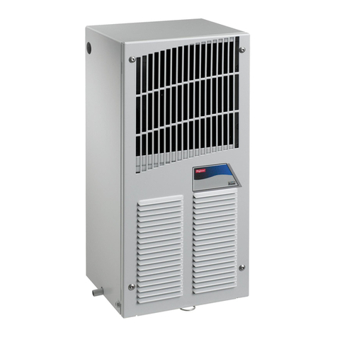
nVent Hoffman SPECTRACOOL N28 User manual

N28 Instruction Manual

SPECTRACOOL
Air Conditioner
n28 Model
INSTRUCTION MANUAL

TABLE OF CONTENTS
NOTE: Some of the information in this manual may not apply if a special unit was ordered. If additional
drawings for a special unit are necessary, they have been inserted. Contact Pentair Equipment
Protection if further information is required.
WARRANTY AND RETURN POLICY
RECEIVING THE AIR CONDITIONER
CAUTION
HANDLING AND TESTING THE AIR CONDITIONER
HOW TO READ MODEL NUMBERS

TECHNICAL INFORMATION
SEQUENCE OF OPERATION
HEATING
COOLING
STANDARD AND OPTIONAL COMPONENT OPERATION
THERMOSTAT
FOR COOLING (75-100 F RANGE):
FOR HEATING (55-65 F RANGE):
NOTE: For testing purposes only, the thermostat stop screw may be removed (on units so
equipped) to allow settings below 70 F. After testing, replace the stop screw and verify that the
thermostat cannot be set below 70 F. Extended operation below 70 F can cause coil freeze ups
resulting in reduced load and/or unit damage.
REMOTE ACCESS CONTROL (OPTIONAL)
HEAD PRESSURE CONTROL (OPTIONAL)
115V/230V TO 10V TRANSFORMER (OPTIONAL)
115V/230V TO 24V TRANSFORMER AND RELAY (OPTIONAL)

SCHEMATICS AND WIRING DIAGRAMS FOR THERMOSTAT CONTROL
GENERIC 115V 1-PHASE SCHEMATIC (ACTUAL UNIT OPTIONS MAY VARY)
89074302
GENERIC 230V 1-PHASE SCHEMATIC (ACTUAL UNIT OPTIONS MAY VARY)

GENERIC 460V 1-PHASE SCHEMATIC (ACTUAL UNIT OPTIONS MAY VARY)

GENERIC 115V 1-PHASE WIRE DIAGRAM (ACTUAL UNIT OPTIONS MAY VARY)
HEATER
BLK12
AMB.
ENC.
HPC
OR C/E
(OPTIONAL)
BLK20
T-STAT
COOLING
RED13
BLK
BLK
BRN
GRN/YEL
IMPELLER
AMBIENT BLU
BLK
BLU19
BLK12
YEL10
BLK11
WHT7
RED13
BLU9
BRN8
BLK20
HEATING
T-STAT
RED30
BRN26
13
MALF
SWITCH
(OPTIONAL)
2
YEL(NO)
RED(COM)
BLU(NC)
BLU29
COMP HTR
(OPTIONAL)
(OPTIONAL)
SUPPRESSOR
THERMAL DISPLAY (OPT.)
TO THERMAL
115(230) V
10 V
DISPLAY
WHT41
BLK40
DOOR SWITCH (OPT.)
RED62
T'FORMER
BLK60
WHT61
YEL65
RELAY
0
1
4
8
2
6
YEL10
YEL10 OR
YEL65
WHT63
WHT64
BLK27
BLK28
SWITCHES
LIMIT
GRN/YEL21
POWER
BLOCK
1
2
WHT15
FAN
ENCLOSURE
BLK14
BLK14
WHT7
BLK11
3
R
START CAPACITOR
BLK23
C
BLK 115V / WHT 230V
BLK 115V / WHT 230V
4
BLU19
BLU21
BLU22
5
43
6
43
6
CUSTOMER
SWITCH
TO
COMPRESSOR
0.L.
S
89073631

GENERIC 230V 1-PHASE WIRE DIAGRAM (ACTUAL UNIT OPTIONS MAY VARY)

GENERIC 460V 1-PHASE WIRE DIAGRAM (ACTUAL UNIT OPTIONS MAY VARY)

DIMENSIONAL DRAWING
WITH THERMOSTATS
&/($1$%/(5(86$%/(
$/80,180,1/(7$,5),/7(5
38//6287)5217
&22/
$,5287
(1&/2685(
$,5,1
5(029$%/(
+$1*,1*7$%6
81&
02817,1*
+2/(6
&22/,1*767$7
+($7,1*767$7
237,21$/
237,21$/$&&(663$1(/
21/<)2581,76:,7++($7(5
$&&(66+2/(72
2''5$,1678%
$0%,(17
$,5,1
:$50
$,5287
89068456

INSTALLATION INSTRUCTIONS

REMOTE ACCESS CONTROL (OPTIONAL)
INTRODUCTION
ENERGIZING THE CONTROLLER
CONTROL STATUS INDICATION
SYMBOL COLOR ICON ON ICON FLASHING

DISPLAYING AND CHANGING PROGRAM VARIABLES
Access:
Navigation:
Adjust:
NOTE: The display will revert to normal temperature display mode if no buttons are pressed
for 60 seconds.
OPERATING PARAMETERS
Parameter Default Value Range Description
ALARM PARAMETERS
Parameter Default Value Description
DISPLAYING TEMPERATURE SENSOR #2
COMPRESSOR RESTART TIME DELAY
ALARM OUTPUT CONTACT

ALARM INPUT CONNECTION
ALARM CONDITION DISPLAY
Alarm Mnemonic Description Cause Result Alarm Relay
AIR CONDITIONER UNIT COMMUNICATION FEATURES
USB COMMUNICATION
ETHERNET COMMUNICATION
Note: ACU has a default IP Address of 192.168.1.2
SOFTWARE AND CONFIGURATION FILE DOWNLOADS

USING THE PC INTERFACE TOOL
USB COMMUNICATION MODE
NOTE: Before connecting unit to the PC, make note of the comm ports present. After the unit
is connected to the PC, a new comm port will be added to the list. Use this new comm port.
ToolsUse Ethernet
Use EthernetComm Port Device IPCommunity
Comm PortTools
VIEWING AIR CONDITIONER UNIT VALUES
ACU Values
Enable Comm
Disable Comm
CHANGING AIR CONDITIONER UNIT VALUES
ACU Values
Settings
Change Setting
ACU Values
VIEWING AND CHANGING ETHERNET INFORMATION
Ethernet Info
Read Ethernet Info
Use DHCP Server
Load Ethernet Info
Use DHCP Server
Load Ethernet Info

ETHERNET COMMUNICATION MODE
ToolsUse Ethernet
Use EthernetComm PortDevice IPCommunity
Device IPCommunity
Each unit has two community strings. One is a Read/Write community string (defaulted to
‘private’) that can be changed by the customer (must be 4 to 8 characters long). The other is a
Read-Only community string (‘public’) and cannot be changed.
VIEWING AIR CONDITIONER UNIT VALUES
ACU Values
Enable Comm
Disable Comm
CHANGING AIR CONDITIONER UNIT VALUES
ACU Values
Settings
Change Setting
ACU Values
VIEWING AND CHANGING ETHERNET INFORMATION
Ethernet Info
Read Ethernet Info
Use DHCP Server
Load Ethernet Info
Use DHCP Server
Load Ethernet Info
ALARM LOG ACCESSIBLE WITH SNMP

REMOTE ACCESS CONTROL PIN-OUT
FUNCTION NAME PIN # WIRE #

SCHEMATICS AND WIRING DIAGRAMS FOR REMOTE ACCESS CONTROL
GENERIC 115V 1-PHASE SCHEMATIC (ACTUAL UNIT OPTIONS MAY VARY)
GENERIC 230V 1-PHASE SCHEMATIC (ACTUAL UNIT OPTIONS MAY VARY)
89115043 REV. A

GENERIC 460V 1-PHASE SCHEMATIC (ACTUAL UNIT OPTIONS MAY VARY)
89115043 REV. A
Table of contents
Other nVent Hoffman Air Conditioner manuals

nVent Hoffman
nVent Hoffman T Series User manual

nVent Hoffman
nVent Hoffman SPECTRACOOL NHZ43 User manual

nVent Hoffman
nVent Hoffman SpectraCool Slim Fit User manual

nVent Hoffman
nVent Hoffman T Series User manual

nVent Hoffman
nVent Hoffman PROAIR CR29 Series User manual

nVent Hoffman
nVent Hoffman X2302 User manual
Popular Air Conditioner manuals by other brands

Daikin
Daikin FTKD42GVM Service manual

Mitsubishi Electric
Mitsubishi Electric Mr.SLIM PKA-RP35GAL Service manual

Mitsubishi Electric
Mitsubishi Electric Mr.Slim PLA-SM71EA Service manual

Trane
Trane IntelliPak SIWG Installation, operation and maintenance

Carrier
Carrier 24ANA1 Infinity Wiring diagram

AirStage
AirStage ARXK07GALH installation manual