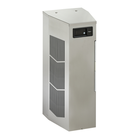
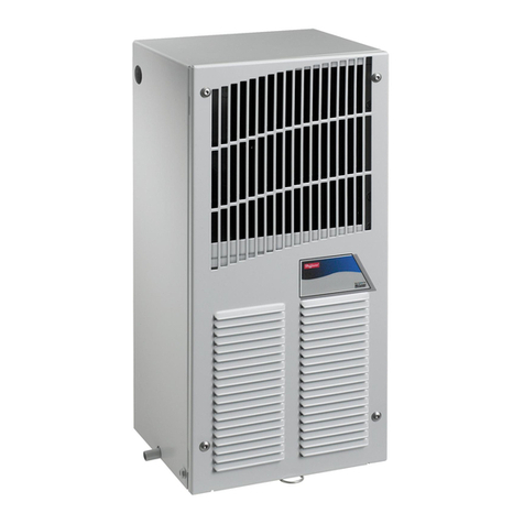
nVent Hoffman X2302 User manual

Extreme AC Air Conditioner
X2302 Model
Instruction Manual
P/N


nVent.com/HOFFMAN
|
3
Note: Some of the information in this manual may not apply if a special unit was ordered. If additional drawings for a special unit are
necessary, they have been inserted. Contact nVent HOFFMAN if further information is required.
WARRANTY AND RETURN POLICY
https://HOFFMAN.nVent.com/en/HOFFMAN/warranty-information
TABLE OF CONTENTS
Warranty and return policy...........................................................................................................................................................................3
Receiving the air conditioner ......................................................................................................................................................................4
Handling and testing the air conditioner ......................................................................................................................................................4
Installation instructions...............................................................................................................................................................................5
Dimension drawing ............................................................................................................................................................................................... 5
Mounting cutout dimensions ............................................................................................................................................................................... 6
Wire diagram.......................................................................................................................................................................................................... 7
Schematics ...........................................................................................................................................................................................................8
Technical information .................................................................................................................................................................................9
Design data ............................................................................................................................................................................................................ 9
Washdown note ....................................................................................................................................................................................................9
Component list .....................................................................................................................................................................................................9
Smart controller .......................................................................................................................................................................................10
Principles of operation ..............................................................................................................................................................................10
Overview .............................................................................................................................................................................................................. 10
Energizing the controller .................................................................................................................................................................................... 10
Control status indication .................................................................................................................................................................................... 10
Displaying and changing program settings ....................................................................................................................................................... 13
To view or access the settings ................................................................................................................................................................. 13
Heat/cool operating parameters ....................................................................................................................................................................... 13
Alarm parameters ............................................................................................................................................................................................... 13
Displaying temperature data on screen ............................................................................................................................................................ 15
Compressor restart time delay .......................................................................................................................................................................... 15
Alarm output contact ......................................................................................................................................................................................... 15
Alarm input connection ...................................................................................................................................................................................... 15
Primary-secondary (PS) mode ........................................................................................................................................................................... 16
Connecting units together in primary/secondary mode .................................................................................................................................. 16
Connecting units together in lead/lag mode .................................................................................................................................................... 17
Air conditioner unit remote communication features ...................................................................................................................................... 18
USB communication ................................................................................................................................................................................. 18
Ethernet communication ........................................................................................................................................................................... 18
Using nVent HOFFMAN PC interface tool ......................................................................................................................................................... 19
USB communication mode ....................................................................................................................................................................... 19
USB communication mode .......................................................................................................................................................................20
Ethernet communication mode ................................................................................................................................................................ 21
Remote access control pin-out ..........................................................................................................................................................................22
Maintenance .............................................................................................................................................................................................23
Inlet air filter ........................................................................................................................................................................................................23
How to remove, clean or install a new inlet air filter ........................................................................................................................................23
Refrigerant loss ...................................................................................................................................................................................................24
Preventive Maintenance/Inspection ..................................................................................................................................................................25
Trouble shooting .......................................................................................................................................................................................26
F-GAS information.....................................................................................................................................................................................28
4
|
nVent.com/HOFFMAN
RECEIVING THE AIR CONDITIONER
Inspect the air conditioner. Check for concealed damage that may have occurred during shipment. Look for dents, scratches, loose
assemblies, evidence of oil, etc. Damage evident upon receipt should be noted on the freight bill. Damage should be brought to the attention
of the delivering carrier -- NOT to nVent Equipment Protection -- within 15 days of delivery. Save the carton and packing material and request
an inspection. Then file a claim with the delivering carrier.
nVent Equipment Protection cannot accept responsibility for freight damages; however, we will assist you in any way possible.
HANDLING AND TESTING THE AIR CONDITIONER
If the air conditioner has been in a horizontal position, be certain it is placed in an upright, vertical or mounting position for a minimum of
five (5) minutes before operating.
CAUTION:
Do not attempt to operate the air conditioner while it is horizontal or on its side, back or front. The refrigeration compressor is filled with
lubricating oil. This will cause permanent damage to the air conditioner and also voids the warranty.
Test for functionality before mounting the air conditioner to the enclosure.
Refer to the nameplate for proper electrical current requirements, and then connect the power cord to a properly grounded power supply.
Minimum circuit ampacity should be at least 125% of the amperage shown in the design data section for the appropriate model. No other
equipment should be connected to this circuit to prevent overloading.
Operate the air conditioner for five (5) to ten (10) minutes. No excessive noise or vibration should be evident during this run period. The
condenser blower (ambient air), the evaporator blower (enclosure air), and the compressor should be running.
Condenser air temperatures should be warmer than normal room temperatures within a few minutes.
The compressor is provided with automatic reset thermal overload protection. This thermo-switch is located and mounted inside the plastic
enclosure clipped to the compressor. The switch operates when the compressor overheats due to clogged or dirty inlet air filter or if ambient
air temperatures exceed nameplate rating or if enclosure dissipated heat loads exceed the rated capacity of the air conditioner. The thermal
overload switch will actuate and stop compressor operation. The blowers will continue to operate and the compressor will restart after it has
cooled to within the thermal overload cut-in temperature setting.

nVent.com/HOFFMAN
|
5
INSTALLATION INSTRUCTIONS
1. Inspect air conditioner and verify functionality before mounting the air conditioner, “HANDLING AND TESTING THE AIR CONDITIONER”
see on page 4.
2. Using the cutout dimensions shown in this manual, prepare the air conditioner opening, and mounting bolt hole pattern for the enclosure.
See “Mounting Cutout Dimensions” on page 6for proper location.
3. Using the gasket kit provided, install gaskets to the enclosure using the cutout and bolt hole pattern as a guide.
4. Mount air conditioner on enclosure using mounting bolts and washers provided to secure unit to enclosure. Torque bolts to 22.5in-lb
(2.5Nm). Allow unit to remain upright for a minimum of five (5) minutes before starting. Caution! Air conditioner must be in upright
position during operation.
5. To avoid cross-threading mounting inserts, start bolts by hand before tightening with a wrench or ratchet driver.
6. Refer to the top of the nameplate for electrical requirements. Connect power from a properly grounded power supply. Use of an extension
cord is not recommended. Electrical circuit should be fused with slow blow or HACR circuit breaker.
7. When the unit is equipped with an automatic temperature controller, the controller is preset at the factory for your convenience and should
not require adjustment.
Dimension drawing
10.23
260
22.32
567
13.64
346
4.49
114
5.08
129
3X
.57
15
5X
.54
14
1.59
40
6.50
165
7.56
192
1.04
27
6.00
152
12X 1/4-20
3.78
96
1.26
32
11.41
290
.48
12
89215771
Condensate
Drain
View of Underside of Unit
Ambient Air In
Cleanable, Reusable
Aluminum Inlet Filter
Mounting Holes
Power In
Enclosure Air In
Cool Air Out
Warm
Air Out
Terminal Block (Power
connections behind
removeable cover)

nVent.com/HOFFMAN
|
9
COMPONENT LIST
1
2
4
5
6
7
8
9
10
11
12
13
14
15
16
17
3
**
** MOUNTING GASKET NOT SHOWN
Reference Part description 115 V 230 V
1Fan, Condenser 89206390SP 89206391SP
2Filter, Air 89203781SP 89203781SP
3Compressor 89109026SP 89108369SP
4Overload, Compressor Thermal 89109877SP 89109878SP
5Switch, HPC 89083016SP 89083016SP
6Switch, MALF 89096948SP 89096948SP
7Filter Drier 52602803SP 52602803SP
8Coil, Condenser 20102001SP 20102001SP
9Coil, Evaporator 89204519SP 89204519SP
10 Controller, Smart 89202719SP 89202719SP
11 Relay, Cooling 10100535SP 10100534SP
12 Capacitor, Compressor 89107709SP 89106525SP
13 Fan, Evaporator 12101201SP 12101202SP
14 Capacitor, Condenser Fan 52603215SP 52603214SP
15 Transformer, Control 10100694SP 10100693SP
16 Heater, 350 W (Optional) 89206006SP 89206007SP
17 Gasket, Mounting 89202697SP 89202697SP

10
|
nVent.com/HOFFMAN
TECHNICAL INFORMATION
Design data
Model Voltage Hz Phase
Full Load
Cooling
Amps
Full Load
Heating
Amps
BTU/Hr @ Max
Ambient
Temperature
Max Amb
Temperature
°F/°C
Shipping
Weight
lb./kg
X230216GXXX 110/115 50/60 1 6.8/6.3 3.3/3.5 2100/2300 131/55 60/27
X230226GXXX 220/230 50/60 1 2.8/2.9 1.7/1.8 1760/1890 131/55 60/27
-XXX will be replaced with a three-digit number designating all desired options. Consult the factory for specific model numbers.
WASHDOWN NOTE
Testing has confirmed that with the cover in place the X2302 Air Conditioner will successfully withstand a clean water washdown procedure
while the unit is energized. If the washdown procedure is performed with the cover removed the unit must first be de-energized, and must be
allowed to dry completely before the cover is reinstalled and power is reapplied.
SMART CONTROLLER
• All Model X2302X6Air Conditioners are equipped with a Smart Controller.
• A Remote Access Control (RAC) optional accessory is available. The RAC can be ordered along with the X2302X6, or if desired, it can be
ordered separately as an upgrade at some later date. The RAC is packaged and shipped separately from the air conditioner since it cannot
fit inside the unit. The RAC is field installable.
PRINCIPLES OF OPERATION
• If electrical power to the air conditioner is interrupted and reapplied immediately (within 3to 5seconds), the compressor may not restart
due to the high back pressure of the compressor. It takes a minimum of one (1) minute after shut-down for the compressor suction and
discharge pressures to equalize in order for the air conditioner to restart.
• Operating the air conditioner below the minimum ambient temperature or above the maximum ambient temperatures indicated on the
nameplate voids all warranties.
• It is recommended that the warranty section of this manual be read in order to familiarize yourself with parameters of restricted operation.
• The moisture that the enclosure air can contain is limited. If moisture flows from the drain tube continuously this can only mean that
ambient air is entering the enclosure. Be aware that frequent opening of the enclosure’s door admits humid air which the air conditioner
must then dehumidify.
Overview
The smart controller is a parametric controller for the complete management of air conditioners. All settings are pre-programmed at the
factory. Cooling/heating setpoint, cooling/heating differential and high/low temperature setpoint are designed to be adjustable by the
operator. All alarms are outputted through the alarm relay. See “AIR CONDITIONER UNIT REMOTE COMMUNICATION FEATURES” on page 18
for remote input and output capabilities.
Energizing the controller
The digital controller is wired and programmed at the factory to operate when power is applied to the air conditioner. In normal condition, the
evap fan starts operating after the completion of the self-evaluation which is less than 30 seconds and fan icon should be illuminated along
with the inlet and outlet temperature data (if an option outlet temperature sensor is installed).
Control status indication
The display has numerous symbols to indicate the various controller functions such as cooling, heating, alarming, evaporator fan, and
heating. Indicators (icons) are steady illuminated on screen when active.
Figure 1Display

nVent.com/HOFFMAN
|
11
Keypad
Symbol Color Icon Indication Icon Status
Red Alarm – active when alarm is detected Flashing when alarm is detected
White
Keypad Select – access to passcode , hold 5sec to turn unit
ON/OFF, parameter menu, parameter setting, write or save to
EEPROM, and hold for 3sec to return to main screen
ON
White Keypad Up – navigate to previous parameter and increasing
parameter variable ON only when reviewing parameters
White Keypad Down – navigate to next parameter and decreasing
parameter variable, all inputs, unit status. ON
Main field
Symbol Color Icon Indication Icon Status
°C White When operating temperature in degrees Celsius ON
°F White When operating temperature in degrees of Fahrenheit ON
Main Field Line 1White Display inlet temperature ON
Main Field Line 2Orange
1. Display outlet temperature in standalone mode if outlet sensor
is present
2. Displays device ID for primary-secondary mode up to 10 units,
1:10 … 10:10 or lead-lag mode up to 2units, 1:2… 2:2
ON
Icons
Symbol Color Icon Indication Icon Status
White Compressor Running
• Flashing while waiting for
compressor to turn ON
• Steady ON while compressor is
running
White Evaporator Running ON
White Electric heater ON ON
White Primary and/or lead controller ON
White Freeze control Compressor and Condenser fan OFF
while illuminated
White Power ON ON

nVent.com/HOFFMAN
|
13
Displaying and changing program settings
To view or access the settings
To access folder menus:
1. Press button to display passcode screen, the screen displays PSd on line 1and 0000 on line 2.
2. Press button to access to passcode , the first digit of 0000 is flashing and press 3more times until the last digit of 0000 flashes.
3. Press arrow two times to change the 0to 2. Press for access to folder menus.
Note: to exit the security level to the main screen wait one minute with no action or Press arrow until LOG Out message displays, then
press button.
To change a parameter setting
1. Once in the folder menu navigate to the desired setting to be changed using the arrow to scroll and button to access a menu or
parameter.
2. To change a parameter Press button and parameter value will begin to flash.
3. Press / arrow to the desire value.
4. Press button to save the setting and the screen will revert to the parameter mnemonic.
Note: if button is not pressed, the new setpoint is not saved.
To exit the parameter settings to the main screen wait one minute with no action or Press arrow few times until ESC displays, then press
button to return to UoF screen. From the UoF screen Press arrow few times until LOG Out message displays, then press button to
return to the main screen.
Selecting ESC returns to folder menu.
Selecting LOG out returns to main screen.
Heat/cool operating parameters
Mnemonic Parameter Description Default Value Range
CSt1Cooling setpoint 80 F
26.7C
72 F to 120 F
22.2to 48.9C
Cd (Cd1)1Cooling differential 7F
3.9C
2F to 25 F
1.1to 13.9C
Cd24Cooling differential 215 F
8.3C
HSt23Heating setpoint 50 F
10.0C
45 F to 60 F
25.0to 33.3C
Hd3Heating differential 7F
3.9C
2F to 25 F
1.1to 13.9C
1. Compressor or cooling turns ON at CSt + Cd and OFF at CSt
2. Heater or heating turns ON at HSt and OFF at HSt + Hd
3. Heating mode is only applied to a unit with heater option
4. Cooling differential 2is only applied to 2-stage compressor and lead-lag application
Alarm parameters
Mnemonic Para Description Default value
Ht High temperature alarm setpoint 125 F
51.7C
Lt Low temperature alarm setpoint 40 F
4.4C
dO Door open alarm setting NC
ArOP Alarm relay output NO
Note: (4) The alarm relay output logic is designed to be configurable

14
|
nVent.com/HOFFMAN
View alarms
Alarms may be viewed when the alerting icon is flashing.
1. On the main screen, press the alerting icon button
2. The screen displays the most recent or newest alarm where the alarm code display on line 1and the alerting icon is now in steady
3. Press arrow to view next alarm if there are more than one
4. Press arrow to display ESC, then press button to return to the main screen
View the alarms in the alarm history folder
1. Follow instructions above to enter the passcode and open the alarm history folder (AHiF).
2. Press button to access to the alarm history.
3. Press arrow to display the mnemonic alarm on line 1and time, month, and day display on line 2. For example, low temp alarm (Lt)
displays on line 1and 09:24 and 0706 display on line 2in sequence. Note that the time, and date recorded in the alarm history is based on
the local real-time-clock if configured after installation.
4. Press arrow to view next alarm. The controller is able to retain up to 25 events
5. Press arrow until the screen displays ESC, then press button to return to the main screen or if no action for longer than
60 seconds the screen will be automatically revert to the main screen.
Note: if no alarms are present then only ESC will be displayed in the folder.
There are seven possible alarms (non-latching) detectable by the controller and are indicated on the controller display. All alarms are accessible
locally. If a nVent HOFFMAN network card (RAC module) is used, alarms are also accessible remotely through the Ethernet and USB connection.
Mnemonic Alarm Description Cause Result Alarm Relay Output
dO Door open alarm Enclosure door opens or
not properly close
Compressor and evap fan
turn OFF in duration of
alarm
Closed
S1FInlet temperature sensor
fault Inlet temp probe failed
No effect on function,
controller continue
operating as normal using
outlet sensor with setpoint
of 50 F (10 C)
Closed
S2FOutlet temperature sensor
fault Outlet temp probe failed No effect on function but
loss freeze protection Closed
LA Malfunction alarm MALF high pressure switch
opens No effect on function Closed
Ht High temp warning Enclosure air exceeds high
temp alarm setpoint No effect on function Closed
Lt Low temp warning Enclosure air drops below
low temp alarm setpoint No effect on function –
FA Frost alarm Evaporator coil freezes
Compressor and condenser
fan turns OFF for the
duration of alarm. Alarm
clears when the outlet
temperature sensor
reaches 59 F (15 C)
Closed

nVent.com/HOFFMAN
|
15
To reset the alarms in alarm history folder
The controller is designed with ability to reset or clear the alarm history
1. Follow instructions above to enter the passcode and open the reset folder (rStF).
2. The screen displays rSAL on line 2and nO on line 1, press button the nO is flashing
3. Press arrow to change nO to YeS, then press button reset the alarms. The screen flashes once and returns to rSAL with nO one line 2
4. Press arrow to navigate to ESC, then press to returns to rStF screen.
5. Press arrow to navigate to LOG Out, then press button to return to the main screen or if no action for longer than 60 seconds the
screen will be automatically reverted to the main screen.
To reset parameters to factory default
This option is ONLY applied if the operator wants to reset all control parameters back to factory default.
1. Follow instructions above to enter the passcode and open the reset folder (rStF).
2. The screen displays rSAL, press arrow to navigate to rSPA and then press button
3. The screen displays rSPA one line 1and the word nO on line 2in steady state, press button and then the word nO is flashing and
ready to change
4. Press arrow to change nO to YES. Press button the screen displays PSd with 0000 on line 2
5. Press button to enter to passcode. Press button few times until the last digit of 0000 flashing
6. Press arrow to change 0to 2, press button to authorize the reset of the parameters
7. The screen returns to rSPA screen in steady state.
8. Press arrow to navigate to ESC, then press to returns to rStF screen.
9. Press arrow to navigate to LOG Out, then press button to return to the main screen or if no action for longer than 60 seconds the
screen will be automatically reverted to the main screen.
Displaying temperature data on screen
There are two temperature probes in the air conditioner where one is reading the enclosure air temperature incoming to the air conditioner
and other is reading the cooled air leaving the air conditioner and entering the enclosure. Both temperature data are displayed on the screen
where line 1is the reading of the inlet temperature and line 2is the reading of the outlet temperature.
Compressor restart time delay
A factory set 3minute (180 seconds) restart delay exists to reduce residual back pressure before allowing the compressor to restart. The
compressor will stay off for the entire restart duration after the compressor is disabled. A flashing compressor icon on the display
indicating that the unit is in a compressor restart delay mode while calling for cooling or waiting for compressor to turn ON.
Alarm output contact
The digital controller has a normally open dry contact alarm output with a resistive load rating of 250VAC @ 5amps max. The two yellow 18 AWG
wires located at the back of the air conditioner provide a connection to this output. Note: do not apply power to this normally open dry contact
(two yellow 18 AWG wire). This alarm relay output is configurable and provides user with the ability to change the configuration to support their
external device. Parameter C21 controls the alarm relay output logic and can be accessed through security code “0022” in the PArF folder.
Para Description Configuration
C21 Alarm relay output logic 0= normally open (NO) – factory default
1= normally closed (NC)
Alarm input connection
The digital controller can accept a dry contact/switch input via the two 18 AWG white wires located at the back of the air conditioner. This
input is associated with the controller display alarm mnemonic dO (door open). To use this feature, remove the splice connector, and connect
the two white wires to customer supplied enclosure door switch in its place.
Note: do NOT apply power to this dry contact input.

16
|
nVent.com/HOFFMAN
Primary-secondary (PS) mode
Note: during normal operation, in both the primary-secondary (PS) and lead-lag (LL) operating modes, line 2displays the device ID, not the
outlet temperature. The outlet temperature can be viewed on line 1by pressing arrow.
Primary-secondary (PS) mode shares the same hardware and source code as standalone mode, but offers more functionality and features.
The controller ships from the factory in Standalone Mode. PS mode is configured manually in the field after the installation. This option
allows the user to operate the air conditioner in a group network with up to 10 units. To support PS mode, three parameters, H01, H02, and
H03 need to be configured. H01 specifies the operating mode, H02 specifies the device ID, and H03 specifies the total number of the units in
the group network.
Before configuring to operate in PS mode, the user should understand the functionality of the PS mode.
1. In the PS mode, all units operate off the cooling/heating setpoint and differential of the primary unit. The system prevents setpoint
changes from secondary units.
2. The primary unit monitors the enclosure temperatures of all the units and manages the ON/OFF status of cooling and heating based on
the unit reporting the highest temperature.
3. When cooling is initiated the primary unit energizes first. Secondary units are energized sequentially at 10 second intervals. When heating
is initiated all units turn on heat together. When cooling or heating is satisfied all units turn off together.
4. If the number of units communicating on the network doesn’t match the value in H03 then the primary unit will display alarm LC, and the
secondary units will display alarm LC1until the communication re-established.
5. Any unit that loses communication with the primary unit will enter standalone mode and continue operating based on its own temperature
probe until communication is re-established.
6. All temperature setpoints and alarms can be viewed remotely if one of the ACUs is equipped with nVent HOFFMAN network card
(RAC module).
7. Best recommendation is to configure the ACU that has nVent HOFFMAN network card to be the primary one.
Connecting units together in primary/secondary mode
Primary - Device ID 1Secondary - Device ID 2Secondary - Device ID 3Secondary - Device ID 10
Figure 2Primary-secondary network connectivity

nVent.com/HOFFMAN
|
17
To configure the controller from single mode to PS mode, simply follow below procedures
1. Before proceeding the PS mode configuration for each controller, make sure that the communication cable is connected from one ACU to
another using a shielded cable with the shield grounded.
2. Press button to display passcode screen, the screen displays PSd on line 1and 0000 on line 2.
3. Press button to access to passcode , the first digit of 0000 is flashing and press 2more times until the third digit 0000 flashes. Press
arrow two times to change 0to 2, then press button to move to the last digit 0020
4. Press arrow two times to change the 0to 2.
5. Press button to access to folder menu and then, the screen displays ALrF
6. Press arrow to navigate to PArF, then press button to access to parameter menu
7. The screen displays C, press arrow to navigate to parameter Hand then, press button to access to parameter Hmenu
Parameter Description Available Range PS Settings Default
H01 Mode
SA (stand alone)
PS (primary-secondary) SAPS (primary-secondary)
LL (lead-lag)
H02 Device ID 1up to 10 1 up to H03 1
H03 Total number of the units
in the group network 1up to 10 2 up to 10 1
8. Set parameter H01 to PS (primary-secondary).
Note: that after H01 = PS, the snowflake icon is illuminated and line 2changes its display information from outlet temperature to device
ID, for example, line 2displays 01:02 where 01 indicates controller #1and 02 indicates the total number of the controllers in a group
network. Keep in mind that the snowflake icon only illuminates on primary controller.
9. Set parameter H02 (device ID) to 1to 10. This device ID will be different for each controller that is connected. The controller set to 1will be
the primary controller. Use numbers sequentially and don’t skip using a number.
10.Set parameter H03 (total number of controllers connected) to 1to 10.
Connecting units together in lead/lag mode
Lead - Device ID 1Lag - Device ID 2
Figure 3Lead-Lag network connectivity

18
|
nVent.com/HOFFMAN
To configure the controller from single mode to LL mode, simply follow below procedures. Perform this configuration for both air conditioners.
1. Before proceeding the LL mode configuration for each controller, make sure that the communication cable is connected from one ACU to
another using a shielded cable with the shield grounded.
2. Press button to display passcode screen, the screen displays PSd on line 1and 0000 on line 2.
3. Press button to access to passcode, the first digit of 0000 is flashing and press 2more times until the third digit 0000flashes. Press
arrow two times to change 0to 2, then press button to move to the last digit 0020.
4. Press arrow two times to change the 0to 2.
5. Press button to access to folder menu and then, the screen displays ALrF.
6. Press arrow to navigate to PArF, then press button to access to parameter menu.
7. The screen displays C, press arrow to navigate to parameter Hand then, press button to access to parameter Hmenu.
Parameter Description Available Range LL Settings Default
H01 Mode
SA (stand alone)
PS (primary-secondary)
LL (lead-lag)
LL (lead-lag) SA
H02 Device ID 1up to 10 1 or 2 1
H03 Total number of the units
in the group network 1up to 10 2 1
H14 LL strategy selection 0-250 0(Alternate each cycle)
1-250 (Alternate hours) 0
8. Set parameter H01 to LL (lead-lag).
9. Set parameter H02 (device ID) to 1for one unit and 2for the other unit.
10.Set parameter H03 (total number of controllers connected) to 2.
11.Set parameter H14 (LL strategy selection) to 0to 250. This is the run time in hours before ACU1and ACU2will alternate being the lead
unit. When set to zero ACU1and ACU2will automatically alternate every cycle.
Air conditioner unit remote communication features
Air conditioners that include the optional nVent HOFFMAN network card (RAC module) have remote communication capabilities utilizing
SNMP, Modbus TCP, EtherNet/IP, Profinet Protocol via Ethernet connection, and Modbus RTU protocol via USB connection.
nVent provides Windows interface application software that is available to download free from nVent support link
https://go.nVent.com/remote-access-control-support-center. The Windows interface application software supports both
Ethernet and USB communication.
USB communication
This communication mode allows direct connection from a laptop (or PC) to the air conditioning unit using a Mini-b USB cable. As stated
above, Modbus RTU is used to communicate between the two devices via USB connection.
Ethernet communication
This communication mode allows remote connection to the air conditioning unit utilizing SNMP, Modbus TCP, EtherNet/IP, and Profinet
protocol. Customers that use their own software can download an MIB file for SNMP, EDS or EtherNet/IP Object file for EtherNet/IP, Coil
Register file for Modbus TCP, and Data Point for Profinet.
Note: the Ethernet card (RAC module) has a default IP Address of 192.168.1.2
Both Ethernet and USB communication allow the ability to:
• Read ACU inlet and outlet air temperature
• Read and change cooling and cooling differential setpoints
• Read and change heating and heating differential setpoints
• Read and change the high and low temperature alarm settings
• Read and change the Gateway IP address, Device IP address, Subnet MASK, Trap IP address, and community string
• Read and change unit identification
• Read and change the state of IP address from static to dynamic or vice versa
• Read and change the air temperature unit of measure (from F to C or vice versa)
• Read current alarm status
• Evaporator fan control setting
• Read and change the control of door open switch

nVent.com/HOFFMAN
|
19
Software and configuration file downloads
As stated above, the PC interface tool, MIB file, EDS and EtherNet_IP Object file, Coil Register file, and Data Point file can be downloaded
from remote access control support center link, https://go.nVent.com/remote-access-control-support-center.
Using nVent HOFFMAN PC interface tool
nVent HOFFMAN PC Interface Tool gives the user the ability to communicate with nVent HOFFMAN air conditioning unit as to read and write
air temperature data, high and low temperature alarm setting, active alarms, and other information from the controller remotely using either
Ethernet or USB connection. With nVent HOFFMAN PC Interface Tool a user has the ability to remotely manage and monitor hundreds of
nVent HOFFMAN air conditioners both domestically and globally at one central location at user’s own pace, so long as all air conditioners are
configured in the same subnet in the network. nVent HOFFMAN PC Interface Tool also supports text message and email alerting to a service
technician when an alarm occurs. In addition, the tool also provides data logging capability for data analysis.
USB communication mode
Note: before connecting the unit to the PC, make note of Comm Ports present. After the unit is connected to the PC, a new Comm Port will
be added to the list. Recommend using the new Comm Port.
• In the nVent HOFFMAN A.C. Monitor main screen, click on Tools and uncheck Use Ethernet
• Click on Tools menu again, the Comm Port menu is now enabled
• Put the mouser icon to the Comm Port and to the right there is small box with dropdown arrow
• Click on the dropdown arrow next to the small box to view the list of the Comm Port
• Write down the list of the Comm Port
• Connect the Mini-b USB cable from the PC or laptop to the A/C unit
• Click on Tools menu and point the mouser icon to the Comm Port, the small box with dropdown arrow presents to the right
• Click on the dropdown arrow and select the newest or higher number of the Comm Port
To view the controller data information from the A/C unit
• In the nVent HOFFMAN A.C. Monitor main screen, select Single ACU Monitor tab.
• Click on Enable Comm button, then the screen will be displayed the enclosure air temperature and other temperature settings information
include the unit of measure.
• The Enable Comm text on the button now changes to Disable Comm.
• To stop the communication, click on the Disable Comm button and it will change to Enable Comm.
To change the temperature settings to the controller
• In the nVent HOFFMAN A.C. Monitor main screen, select Single ACU Settings tab.
• Note: the Change Settings button is disable and all settings are grayed out. Click on Read Settings button, all settings are now displayed
on screen and the Change Settings button is now enable.
• To change any of the temperature setting, Unit ID, or Station Name, simply click up/down arrow on right of the box or highlight the current
value and type the new value in the box.
• Check the box on the left, then click on Change Setting buttons to save the new setpoint.
• Click on Read Settings again to verify the new setpoint.
• Select Single ACU Monitor tab and click on Enable Comm to read the new temperature settings from the controller.
• Each of the setpoint should match the new variables that just entered from the Single ACU Settings tab.
To view and change the ethernet card (RAC) information
• In the nVent HOFFMAN A.C. Monitor main screen, select Single ACU Ethernet Info tab and notice that the Reprogram ACU button is disabled.
• Click on Read Ethernet Info button, the Ethernet information will be displayed and the Reprogram ACU button is enable.
• To change the Ethernet configuration such as Device IP Address, Gateway IP, and Trap IP, make sure to change the Community string to
private from public. Note that case is very sensitive. The wording must be lower case only.
• Enter the new network configuration to Device IP address, Gateway IP, and Trap IP, then click on Reprogram ACU button to write to the
network card.
• In order to be recognized the new networking configurations in local network, cycle power to the A/C unit is required.

20
|
nVent.com/HOFFMAN
To change the static network to dynamic network mode
• In the Single ACU Ethernet Info tab screen, click on Read Ethernet Info button to read the network card information.
Note: the Reprogram ACU button is now enable.
• Check the box next to the Use DHCP Server on the upper left corner of the screen.
• Click on Reprogram ACU button. Now the network is switched to dynamic from static mode.
• To change the dynamic mode to static mode, in the Single ACU Ethernet Info tab window click on Read Ethernet Info button.
• Uncheck the box next to the Use DHCP Server on the upper left corner of the screen.
• Click on Reprogram ACU button to switch to static mode.
USB communication mode
Note: before connecting the unit to the PC, make note of Comm Ports present. After the unit is connected to the PC, a new Comm Port will
be added to the list. Recommend using the new Comm Port.
• In the nVent HOFFMAN A.C. Monitor main screen, click on Tools and uncheck Use Ethernet.
• Click on Tools menu again, the Comm Port menu is now enabled.
• Put the mouser icon to the Comm Port and to the right there is small box with dropdown arrow.
• Click on the dropdown arrow next to the small box to view the list of the Comm Port.
• Write down the list of the Comm Port.
• Connect the Mini-b USB cable from the PC or laptop to the A/C unit.
• Click on Tools menu and point the mouser icon to the Comm Port, the small box with dropdown arrow presents to the right.
• Click on the dropdown arrow and select the newest or higher number of the Comm Port.
To view the controller data information from the A/C unit
• In the nVent HOFFMAN A.C. Monitor main screen, select Single ACU Monitor tab.
• Click on Enable Comm button, then the screen will be displayed the enclosure air temperature and other temperature settings information
include the unit of measure.
• The Enable Comm text on the button now changes to Disable Comm.
• To stop the communication, click on the Disable Comm button and it will change to Enable Comm.
To change the temperature settings to the controller
• In the nVent HOFFMAN A.C. Monitor main screen, select Single ACU Settings tab.
• Note: that the Change Settings button is disable and all settings are grayed out. Click on Read Settings button, all settings are now
displayed on screen and the Change Settings button is now enable.
• To change any of the temperature setting, Unit ID, or Station Name, simply click up/down arrow on right of the box or highlight the current
value and type the new value in the box.
• Check the box on the left, then click on Change Setting buttons to save the new setpoint.
• Click on Read Settings again to verify the new setpoint.
• Select Single ACU Monitor tab and click on Enable Comm to read the new temperature settings from the controller.
• Each of the setpoint should match the new variables that just entered from the Single ACU Settings tab.
To view and change the ethernet card (RAC) information
• In the nVent HOFFMAN A.C. Monitor main screen, select Single ACU Ethernet Info tab and notice that the Reprogram ACU button is disabled.
• Click on Read Ethernet Info button, the Ethernet information will be displayed and the Reprogram ACU button is enable.
• To change the Ethernet configuration such as Device IP Address, Gateway IP, and Trap IP, make sure to change the Community string to
private from public. Note that case is very sensitive. The wording must be lower case only.
• Enter the new network configuration to Device IP address, Gateway IP, and Trap IP, then click on Reprogram ACU button to write to the
network card.
• In order to be recognized the new networking configurations in local network, cycle power to the A/C unit is required.
Table of contents
Other nVent Hoffman Air Conditioner manuals

nVent Hoffman
nVent Hoffman T Series User manual

nVent Hoffman
nVent Hoffman T Series User manual

nVent Hoffman
nVent Hoffman SPECTRACOOL N28 User manual

nVent Hoffman
nVent Hoffman SpectraCool Slim Fit User manual

nVent Hoffman
nVent Hoffman PROAIR CR29 Series User manual

nVent Hoffman
nVent Hoffman SPECTRACOOL NHZ43 User manual
Popular Air Conditioner manuals by other brands

Daikin
Daikin FTKD42GVM Service manual

Mitsubishi Electric
Mitsubishi Electric Mr.SLIM PKA-RP35GAL Service manual

Mitsubishi Electric
Mitsubishi Electric Mr.Slim PLA-SM71EA Service manual

Trane
Trane IntelliPak SIWG Installation, operation and maintenance

Carrier
Carrier 24ANA1 Infinity Wiring diagram

AirStage
AirStage ARXK07GALH installation manual