manuals.online logo
Brands
  1. Home
  2. •
  3. Brands
  4. •
  5. nVent SCHROFF
  6. •
  7. Power Supply
  8. •
  9. nVent SCHROFF maxpower MAX LR User manual

nVent SCHROFF maxpower MAX LR User manual

Bedienungsanleitung
Operating instructions
Notice d’utilisation
MAX LR
MAX UR
(13100-133 –13100-134)
73972-069/52 Rev.002
Attention !
Observer les prescriptions et
règles de sécurité!
Avant la mise en service, lire la
notice d’utilisation.
Raccorder le conducteur de terre
(PE).


Pour obtenir une protection contre
les contacts directs, l’appareil doit
obligatoirement être monté dans
un boîtier excluant toute
possibilité de contact avec des
parties sous tension.
L’appareil ne peut être ouvert que
par des personnes qualifiés!
La protection anti-feu est à
assurer par une enveloppe
indépendante de l’alimentation.
Consignes de sécurité
L’alimentation doit être munie d’une
face avant appropriée, afin d’éviter
tout contact avec des parties sous
tension.
Precautions!
Please read the safety
instructions carefully!
Please read these operating
instructions carefully before
switching on.
Connect the PE conductor before
operating.
The power supply should be
mounted in a case to avoid risk
of direct contact with live parts.
The power supply unit should be
opened by authorized service
personnel only!
Ensure correct installation for
conformity to fire regulations.
Safety instructions
Operate only with suitable front
panel to avoid contact with voltage-
bearing parts!
Vorsicht!
Sicherheitsvorschriften,
-bestimmungen und -hinweise
beachten!
Vor dem Betrieb Bedienungs-
anleitung lesen.
Vor dem Betrieb PE-Leiter
anschließen.
Direkter Berührschutz erfordert
unbedingt den Einbau in ein
Gehäuse, welches das Berühren
spannungsführender Teile
ausschließt.
Das Gerät darf nur von
Fachpersonal geöffnet werden!
Brandschutz ist durch das
übergeordnete Gefäßsystem
sicherzustellen
Sicherheitshinweise
Nur mit geeigneter Frontplatte
betreiben, um die Berührung
spannungsführender Teile zu
verhindern!
Afin d’éviter les couplages parasites,
les câblages secteur et secondaires
doivent cheminer séparément.
Toute interruption de la ligne de
protection à l’intérieur ou à
l’extérieur de l’alimentation, de
même qu’une déconnexion de cette
ligne, peuvent rendre l’appareil
dangereux. Tout acte intentionnel
dans ce sens est strictement interdit.
Avant de remplacer le fusible,
couper l’appareil du secteur
L’alimentation ne dispose que d’une
protection unipolaire. Si le dispositif
de connexion au secteur est de
nature â favoriser une inversion
polaire, il faut prévoir un second
fusible.
Le couplage en série de plusieurs
alimentations peut occasionner des
tensions mortelles aux sorties ( à
partir de 60 VDC). Limite de tension
SELV = 60 VDC max.
Lors du montage de l’alimentation,
respecter les mesures de sécurité
prévues par la norme EN 60950.
Observer les prescriptions et règles
de sécurité générales.
Um Störungseinkopplungen zu
vermeiden, müssen Netz- und
Ausgangsleitungen getrennt verlegt
werden.
Jede Unterbrechung der Schutz-
leitung innerhalb oder außerhalb
des Gerätes oder die Abkoppelung
des Schutzleiteranschlusses kann
das Gerät gefährlich machen;
absichtliche Unterbrechung ist
untersagt!
Vor dem Sicherungswechsel
Gerät vom Netz trennen.
Die Geräte sind werkseitig nur
einpolig abgesichert. Bei Netz-
anschluß mit polverwechselbaren
Steckvorrichtungen ist eine zweite
Sicherung vorzusehen.
Durch Serienschaltung (Reihen-
schaltung) mehrerer Stromversor-
gungen können an den Ausgängen
lebensgefährliche Spannungen
(ab 60 VDC) auftreten
(SELV-Spannung nur bis 60 VDC)!
Beim Einbau des Gerätes Sicher-
heitsmaßnahmen nach EN 60950
beachten!
Allgemeine Sicherheitsvorschriften
und -bestimmungen beachten!
To avoid interference, the mains/line
and output connections must be
physically separated from one
another.
Do not disconnect ground/earth
inside or outside the power supply.
The company cannot be held
reponsible for unsafe operating
conditions resulting from deliberate
disconnection!
Disconnect the mains/line voltage
from the unit before changing the
fuse.
The units are fused for live only.
A second fuse should be used for
the neutral connection where the
polarity of the connectors can be
reversed.
When operating several power
supplies in series, dangerous
voltages may occur at the output
terminals; SELV voltage must be
limited to 60 VDC!
When mounting the unit read the
safety instructions to EN 60950!
The general safety regulations must
be observed.
maxpower
Wide Range
SCHROFF GMBH www.schroff.biz D/UK/F 11/06
Langenalber Straße 96-100, D-75334 Straubenhardt, Tel. (07082) 794-0, Fax (07082) 794-200
11399005
Vor Inbetriebnahme diese Bedienungsanleitung sorgfältig lesen! Entstehen
durch Nichtbeachtung Schäden, erlöschen die Garantieansprüche.
Diese Dokumentation wurde mit größter Sorgfalt erstellt. Dennoch können
wir für die vollständige Richtigkeit keine Garantie übernehmen.
Please read these operating instructions carefully before applying power.
The warranty is subject to correct input voltages being applied. Repairs or
modifications made by anyone other than SCHROFF will invalidate the war-
ranty. This documentation has been compiled with the utmost care. We
cannot however guarantee its correctness in every respect.
Avant la mise en service, veuillez lire attentivement la présente notice
d'utilisation. Tout dommage dû à l'inobservation de nos instructions n'est
pas couvert par notre garantie. La présente documentation a été réalisée
avec le plus grand soin mais nous déclinons toute responsabilité en cas
d'erreur ou d'omission.
EN 60950
Technische Daten Technical Data Caractéristiques techniques
MAX LR MAX UR
Eingangsgrößen Input parameters Valeurs d’entée 13100 - 133 - 134
Netzspannung Nennwerte V
AC
Mains/line voltage Nominal values V
AC
Tension secteur Valeurs nominales V
AC
100 – 240 V
AC
Arbeitsbereiche Operating ranges Plage de fonction-
nement 90 – 254 V
AC
Netznennstrom bei 90 V
AC
Mains/line current at 90 V
AC
Courant nominal pour 90 V
AC
1,6 A
Netzfrequenzbereich Mains/line frequency Fréquence secteur 50 – 60 Hz
Power Factor Correction gemäß Power Factor Correction in accordance
with Power Factor Correction selon EN 61000-3-2
Wirkungsgrad abhängig von eingestellter UA Efficiency depending on set UA Rendement selon préréglage UA 64 % – 80 % 70 % – 82 %
Einschaltstrom I
P
( bei 230 V
AC
) Current at switch-on I
P
( at 230 V
AC
) Courant d’appel I
P
( pour 230 V
AC
) < 20 A
Ausgangsgrößen Output parameters Valeurs de sortie
190 / 90 VAC
Ausgangsleistung max. (50 °C) [ W ] Max. output W (50 °C) [ W ] Puissance de sortie maximale (50 °C) [ W ] 100 / 72 W 102 / 76,8 W
Ausgangsspannung
[ V ] Werkseitig
2)
Output voltage
[ V ] pre-set
2)
Tension de sortie
[ V ] Réglage usine
2)
12 V 24 V
Einstellbereich
1)
∆V Adjustment range
1)
∆V
Plage de réglage
1)
∆V
4,5 V – 17 V 16 V – 30 V
Ausgangsstrom
[ A ] 0 ... 50 °C Output current
[ A ] 0 ... 50 °C Courant de sortie
[ A ] 0 ... 50 °C 5,9 A / 4,23 A 3,4 A / 2,56 A
70 °C 70 °C 70 °C 4,23 A / 3,38 A 2,56 A / 2,08 A
Strombegrenzung Konstandstrom Current Limit constant current Limitation de courant courant constant ja / yes / oui
Restwelligkeit / Störspannung
(BW: 30 MHz) [mV
PP
]Residual ripple / Interference voltage
(BW: 30 MHz) [mV
PP
]Ondulation résiduelle / Tension parasite (BP:
30 MHz) [mV
PP
]< 100 < 150
Netz- und Lastausregelung, statisch
( Lastwechsel 0 - 100 % ) [mV
PP
]Load control, static
( load change 0 - 100 % ) [mV
PP
]Régulation en charge statique
( variation de charge 0 - 100 % ) [mV
PP
]< 120 < 250
Temperaturkoeffizient Temperature coefficient Coefficient de température -0,015%/K
CSB und Ausgang über Diode entkoppelt CSB and output via decoupling diode CSB et Sortie découpling par diode eingebaut / built in / monté
Dynamische Regelabweichungen
(Lastwechsel: 10 ... 100% mit 100 Hz;
dI/dt = 0,25 A/µs)
Dynamic control deviations
(Load change: 10 ... 100% at 100 Hz;
dI/dt = 0.25 A/µs)
Valeurs dynamiques de sortie
(Variation de charge: 10 ... 100% avec 100 Hz;
dI/dt = 0,25 A/µs)
Gesamtausregelzeit,
Toleranz 1% x V
1Nenn
[ms] Total control time,
Tolerance 1 % x V
1
nom
[ms] Temps de réponse global,
Tolérance 1% x V
1
nom
[ms] < 0,2 < 0,2
Überschwingweite und Unterschwingweite
[ mV ] Overshoot and undershoot [ mV ] Amplitude de dépassement et amplitude
négative [ mV ] < 180
Schutz- und
Überwachungseinrichtungen Protection and
control features Dispositifs de protection
et surveillance
Einschaltzeit Soft start delay Temps de montée < 0,8 s
Netzsicherung, High Breaking träge Mains/line fuse, high breaking slow Fusible secteur, high breaking slow 4 A / 250 V
AC
, 5 x 20 mm, DIN EN 60127-2/V
4)
Netzausfallüberbrückung bei V
AC
= 90 V und
100 % Last in Abhängigkeit von der
eingestellten UA
Mains/line failure buffer at V
AC
= 90 V
and 100 % load depending on set UA Pontage microcoupures secteur avec
V
AC
= 90 V et charge 100 % selon préréglage
UA
bis 12 V > 20 ms
12 V – 17 V > 10 ms bis 24 V > 20 ms
24 V – 28 V > 10 ms
28 V – 30 V > 5 ms
Überspannungsschutz OVP begrenzt die UA
auf Over-voltage protection limits UA to Protection surtensions OVP limite la tension
UA à: < 22 V < 38 V
Fernfühlen kompensiert Remote control compensated Compensation max. 0,5 V
Signalisierung „Ausgangsspannung ok“ “Output OK“ Signal Signalisation «tension de sortie OK» Signal „Output OK“, active high
High Pegel [ V ] High Pegel [ V ] High signal [ V ] 3 V – 20 V 13 V – 20 V
Zeitverzögerung Delay Temporisation 100-250 ms
Prüf- und Umweltbedingungen Test and environmental specifications Conditions de test et d’environnement
Klimaprüfung nach Climatic test to Epreuve climatique selon IEC 68-2-38
Schock- und Vibrationstest gemäß
Beschleunigung 2 g Shock and vibration tests in accordance
Acceleration 2 g Tests de chocs et vibrations selon
Accélération 2 g EN 60068-2-6
Höhe 3 HE / Tiefe 160 mm / Breite [TE] Hight 3 U / depth 160mm / Width [HP] Hauteur 3 U / Prof. 160 mm, Largeur [F] 6
Gewicht (Masse) Weight Poids (masse) 0,55 kg
CE Störaussendung CE Transmission Compatibilité
électromagnétique
CE
Emission EN 50081-1
EN 55011 class B
Störfestigkeit,
Schärfeklasse 3 Susceptability,
degree of severity 3 CEM Immunité,
sévérity 3 EN 50082-2,
EN 61000-4-2, EN 61000-4-3, EN 61000-4-4,
EN 61000-4-5, EN 61000-4-6, EN 61000-4-11
Sicherheit,
Schutzklasse 1 Safety,
Protection class 1 Sécurité,
Classe de protection 1
entspricht / corresponds to / correspond à
EN 60950
Hochspannungs-
prüfung nach
EN 60950
Eingang-Ausgang High voltage test
to EN 60950 input-output Tests haute-tension
selon EN 60950 Entrée-Sortie 4,3 kV
DC
3)
Eingang-PE input-PE Entrée-Masse 2,2 kV
DC
3)
Ausgang-PE output-PE Sortie-Masse 0,7 kV
DC
3)
Netzgerät wartungsfrei Power supply, maintenance-free Alimentation sans entretien Ja / yes / oui
Kühlart Cooling Refroidissement Convection
Umgebungstemperatur
Betrieb / Lagerung Ambient temperature Operation / Storage Température ambiante Service / Stockage 0 ... 70 °C / -20 ... + 85 °C
MTBF bei Vollast, T
U
= 40 °C MTBF at full load, Ta= 40 °C MTBF à pleine charge, Ta= 40 °C 270000 h ( 5 V – 220000 h )
1) Bei Erhöhung der Ausgangsspannung ∆V
max. Ausgangsleistung beachten.
2) Toleranz ± 50 mV.
3) ACHTUNG: Hochspannungsprüfung wurde durchge-
führt. Bei erneuter Prüfung darf max. 80% der Prüf-
spannung angelegt werden. Bei unsachgemäßer
Prüfung (z.B. manche Bauteile müssen kurzgeschlos-
sen werden) kann das Gerät zerstört werden.
1)
When increasing the output voltage ∆V check the
maximum output power.
2)
Tolerance ±50 mV.
3)
CAUTION: A high voltage test has been carried out.
Any repeat test must be carried out at max. 80% of
the test voltage. If the test is carried out incorrectly
(e.g. some components have to be short-circuited),
the unit may be destroyed.
1) Lorsqu’on augmente la tension de sortie ∆V
il faut tenir compte de la limitation de puissance.
2) Tolérance ±50 mV.
3) ATTENTION: Les tests haute-tension ont été effec-
tués. En cas de répétition de ces tests, uniquement 80
% de la tension d’essai peut être appliquée. En cas de
tests non appropriés (certains composants doivent
être mis en court-circuit), l’appareil peut être détruit.
Pos.
Item
Repère
Benennung
Description
Désignation
Bestell-Nr.
Order No.
Référence
1Netzgerät, Teileinsatz 3 HE nach DIN 41494, Teil 5
Power Supply, Plug-in unit 3 U to DIN 41494, part 5
Alimentation, Module enfichable 3 U, selon DIN 41494 partie 5
2Steckverbinder Messerleiste
Male connector
Connecteur mâle H 15 M, DIN 41612
3Codierleiste, Kammleiste
Coding strip, Female strip
Détrompeur, Peigne
4Codierleisten-Gegenstück
Coding strip
Réceptacle détrompeur
60800-123
5Steckverbinder-Gegenstück
Female connector
Connecteur femelle
69001-733
6
HF Frontplatte 6 TE (seitlich geschlitzt) mit Befestigungsmaterial
EMC front panel 6 HP with slots incl. assembly parts
Face avant HF 6 F (avec fentes latérales) et pièces de fixation
21006-954
7Sicherung intern
Fuse internal
Fusible secteur
8Power LED grün, versorgt durch die Ausgangsspannung
Power LED green, supplied by the ouput voltage
Power LED verte, alimentée par tension de sortie
9∆V : Einstellung der Ausgangsspannung
∆V : Adjustment of the output voltages
∆V : Réglage tensions de sortie
TE = HP = F
Aufbau / Assembly / Montage
DIJM0031
Maßbilder / Dimensions / Dimensions
DIJM0001
Fühlerleitungbetrieb (Last)
Die Fühlerleitungen werden polrichtig
direkt an der Last angeschlossen. Die
Leitungen müssen verdrillt oder abge-
schirmt sein (Schirm mit PE verbin-
den). Für optimale Störspannungs-
unterdrückung sollte negative Aus-
gangsleitung mit Schutzleiter (PE, Pin
32) verbunden werden.
Fühlerleitungbetrieb (lokal)
Die Senseanschlüsse werden polrich-
tig direkt am Power Supply gebrückt.
Operation with sense lines
(load)
The sense lines are connected directly
to the load with the correct polarity.
The lines must be twisted or screened
(connect screen with PE). For optimum
interference suppression, the negative
output should be connected to the pro-
tective GND/earth (PE, pin 32).
Operation with sense lines
(local)
The sense connections are bridged
directly to the power supply with the
correct polarity.
Utilisation avec lignes de
compensation (charge)
Les lignes de compensation doivent être
raccordées directement à la charge en
respectant la correspondance des
polarités. Elles doivent être torsadées ou
blindées (raccorder le blindage au
conducteur de protection PE). Pour
obtenir une neutralisation optimale des
tensions parasites , la ligne négative
devrait être reliée au conducteur de
protection (PE, broche 32).
Utilisation avec lignes de
compensation (local)
Les lignes de compensation doivent être
pontées directement en sortie
d´alimentation en respectant la
correspondance des polarités.
Prinzipschaltbild, Steckerbelegung / Circuit diagram, Connector pin-out / Schéma de principe, Brochage
DIJM0032
DIJM0071
DIJM0072
DIJM0033
+
-
+
-
PSU 2
PSU 1
+
-
RL
V1
V
1
Leistungsbegrenzung
Zum Schutz des Gerätes muss der
Anwender bei Temperaturen > 50 °C
die Ausgangsleistung reduzieren.
Strombegrenzung
Die Geräte sind für Dauerkurzschluss
ausgelegt. Der Ausgangsstrom wird
gemäß einer U/I-Kennlinie begrenzt.
Strombegrenzung ist für 240 Vp
Betrieb eingestellt. Bei 100 VpBetrieb
muss der Ausgangsstrom reduziert
werden (siehe Tabelle). Steht eine
Überlast bei 100 VpBetrieb längere
Zeit an, schaltet das Netzgerät ab.
Wiederanlauf durch Netz aus-/
einschalten.
Wird die Ausgangsspannung vom
Anwender über die max. einstellbare
Ausgangsspannung erhöht, muss er
sicherstellen, dass der maximale Aus-
gangsstrom um den gleichen Faktor
verringert wird.
Beispiel: U
DC
+ 10 % => I
DC
- 10 %.
Überspannungsschutz (OVP)
Der OVP ist über eine zweite Regel-
schleife realisiert. Schwellen siehe
Spezifikationen.
Bei einem Fehler der OVP-Schaltung
legieren die interne Schutzdioden
durch. Diese müssen werkseitig ausge-
tauscht werden.
Serienschaltung
Sehen Sie am Ausgang externe Invers-
dioden vor. Bei Serienschaltung kön-
nen am Ausgang berührungs-
gefährliche Spannungen auftreten:
SELV-Spannung nur bis 60 V
DC
.
Parallelschaltung
Zur Leistungserhöhung oder Redun-
danzbetrieb werden die Ausgänge der
Netzgeräte parallel verbunden. Es
erfolgt eine geregelte Lastaufteilung
wenn der Current Share Bus der Netz-
geräte miteinander verbunden ist (Pin
22, max. 12 Geräte parallelschaltbar,
max. Ausgangsleistung ca. 0.9*P
max.
).
Damit im Redundanzbetrieb alle Netz-
geräte arbeiten ist eine Grundlast von
0,1*P
max
erforderlich.
Die Entkoppeldiode ist eingebaut.
Netzspannung
Die Power Supplies haben einen Weit-
bereichseingang (90 V
AC
– 254 V
AC
).
Output OK Signal
Das Signal „Output OK“ zeigt an, ob die
Ausgangsspannung vorhanden ist
(siehe Diagramm Signal „Output OK“).
Output power limiting
In order to protect the unit, the user must
reduce the output currents at
temperatures > 50 °C.
Current limiting
The power supply features short-circuit
protection. The output current is limited
according to a U/I diagram. Current
limiting is set for 240 Vpoperation. With
100 Vpoperation the output current
must be limited (see table). If an
overload in 100 Vpoperation persists
for a long while, the power supply
switches off. Restart using the power
on/off switch.
If the output voltage is increased by the
user to above the maximum settable
output voltage, the maximum output
current must be reduced by the same
factor.
Example: VDC + 10 % => IDC - 10 %.
Over-voltage protection (OVP)
The OVP is realized by means of an
additional loop. For thresholds, please
refer to the specifications.
If there is a fault in the OVP-circuit, the
internal fuse breaks. The fuse must be
changed
Series operation
External inverse diodes should be used
at the output. Dangerous voltages may
occur at the output with series
operation:
SELV voltage only up to 60 VDC.
Parallel operation
The unit outputs are set up for parallel
operation to increase the output power
or for redundancy. The load share
control operates if the Current Share
Buses of the unit are linked together(Pin
22 max 12 units). max. output
performance approx. 0.9*Pmax. So that
all power supplies work in redundancy
mode, a basic load of 0.1*Pmax is
required.
The decoupling diode is built in.
Mains/line voltage
The power supplies have a broad
range input (90 VAC – 254 VAC).
Output OK Signal
The Output OK Signal is on if there is an
existing output voltage (see diagram
Signal “Output OK“).
Limitation de puissance
Afin de protéger l’alimentation, l’utilisateur
doit réduire le courant de sortie si la
température est > 50 °C.
Limitation de courant
Les alimentations sont conçues afin de
pouvoir supporter un court-circuit
permanent. Le courant de sortie est limité
selon une courbe U/I. La limitation de
courant est préréglée pour un
fonctionnement à 240 Vp. Pour un
fonctionnement à 100 Vp, le courant de
sortie doit être réduit (voir tableau). En cas
de surcharge prolongée lors d'un
fonctionnement à 100 Vp, l'alimentation
est coupée. Pour redémarrer utliser
l’intérupteur.
Dans le cas où la tension de sortie est
réglée au delà de la valeur maximale de
réglage par l'utilisateur, le courant
maximal de sortie doit être réduit en
conséquence.
Exemple: UDC + 10 % => IDC - 10 %.
Protection contre les surtensions
L’OVP est réalisée par une régulation
séparée. Voir la courbe des
caractéristiques techniques pour les
limites. S’il y a défaut sur l’OVP, les diodes
de protection sont mises en court-circuit
et doivent être remplacées en usine.
Branchement en série
Il faut prévoir des diodes de protection
contre les inversions de polarité. Lors
d’une mise en série, des tensions
dangereuses peuvent apparaître à la
sortie:
tension SELV uniquement jusqu’à 60 VDC.
Branchement en parallèle
Pour accroitre la puissance ou pour une
utilisation en redondance des
alimentations les sorties seront reliées en
parallèle. Une répartition autonome de la
charge est assurée lorsque les sorties
Current Share Bus des alimentations sont
reliées entre elles (broche 22, max. 12
alimentations en parallèle, tension max.
de sortie env. 0.9*Pmax). Pour qu’en mode
de redondance toutes les alimentations
soient en service il faut une charge
minimale de 0,1*Pmax.
La diode de découplage est intégrée.
Adaptation de la tension secteur
L´alimentation dispose d´une plage
d´entrée secteur étendue. Elle s´adapte
automatiquement à la tension secteur
(90 VAC – 254 VAC).
OK Signal Output
Le signal Output OK indique la présence
ou non de la tension de sortie (voir
schéma Signal «Output OK»).
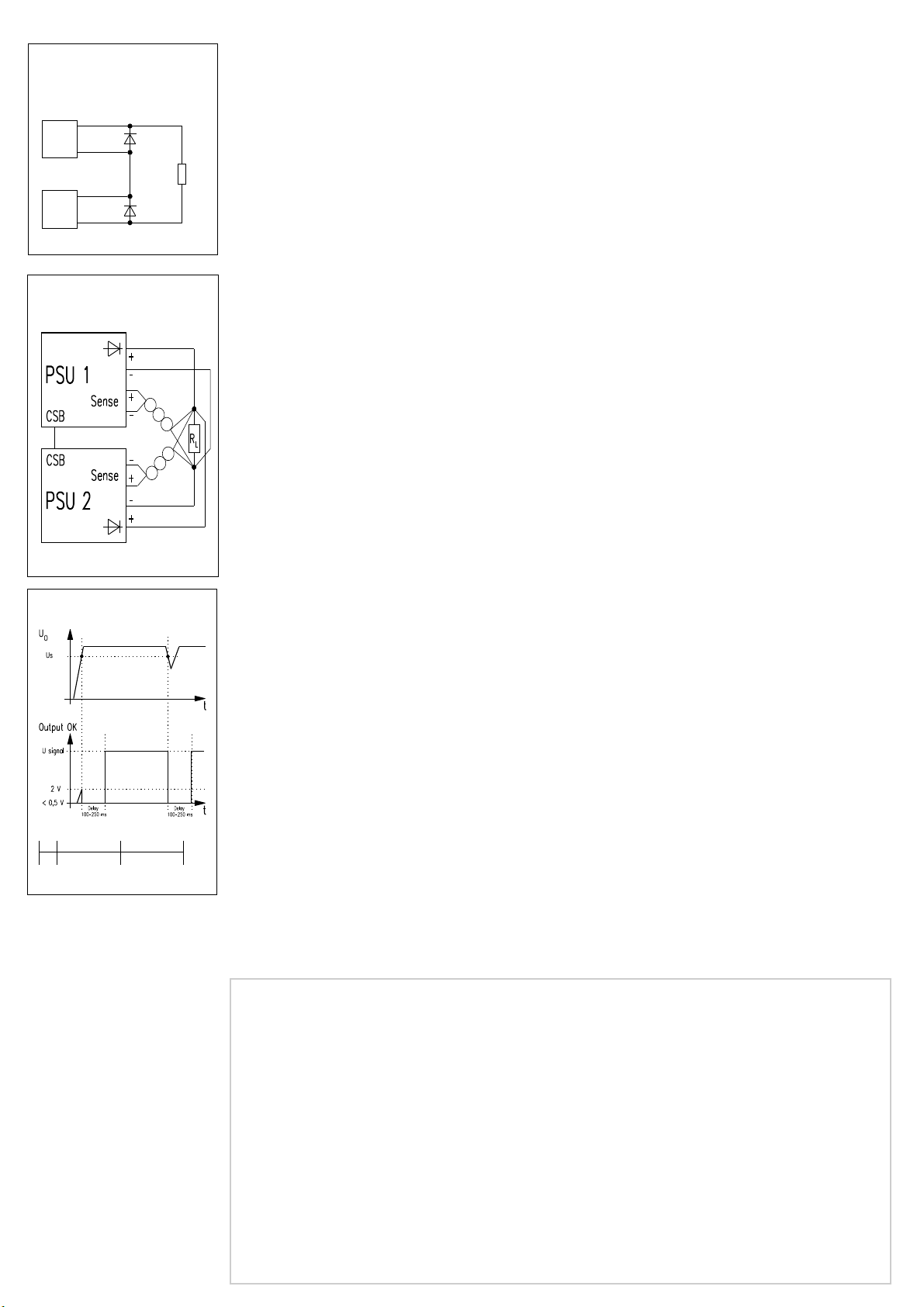
Parallelschaltung (CSB)
Parallel operation
Branchement en parallèle
Serienschaltung
Series operation
Branchement en série
Garantiebedingungen
Leistungsdauer
Für dieses Produkt leisten wir 2 Jahre Garantie.
Der Anspruch beginnt mit dem Tage der
Auslieferung.
Umfang der Mängelbeseitigung
Innerhalb der Garantiezeit beseitigen wir kostenlos
alle Funktionsfehler am Produkt, die auf mangelhafte
Ausführung bzw. Materialfehler zurückzuführen sind.
Weitergehende Ansprüche – insbesondere für
Folgeschäden – sind ausgeschlossen.
Garantieausschluß
Schäden und Funktionsstörungen verursacht durch
Nichtbeachten unserer Bedienungsanleitung sowie
Fall, Stoß, Verschmutzung oder sonstige unsach-
gemäße Behandlung fallen nicht unter die Garantie-
leistung.
Die Garantie erlischt, wenn das Produkt von
unbefugter Seite geöffnet wurde. Eingriffe erfolgt
sind oder die Seriennummer am Produkt verändert
oder unkenntlich gemacht wurde.
Abwicklung des Garantieanspruches
Das vorliegende Produkt wurde sorgfältig geprüft
und eingestellt.
Bei berechtigten Beanstandungen schicken Sie uns
das Produkt bitte zurück. Zur Erhaltung Ihres
Garantieanspruches beachten Sie bitte folgendes:

Legen Sie eine möglichst genaue Beschreibung
des Defektes bei.

Das Produkt ist im Original-Karton oder gleich-
wertiger Verpackung einzusenden und zwar
versichert und portofrei.
Warranty conditions
Duration
This product has a warranty of 2 years.
The warranty begins on the day of delivery
Cover of defects
Within the warranty period Schroff will repair free of
charge any faulty functioning of the product
resulting from faulty design or defective material.
All other claims under the warranty are excluded, in
particular consequential damage.
Warranty exclusion
The warranty does not cover damage or functional
defects caused by non-adherence to the
Company´s operating instructions or such caused
by dropping, knocking, contamination or other
untoward handling. The warranty is invalidated if
the product is opened by unauthorized personnel,
tampered with or the serial number on the product
has been changed or rendered illegible.
Claims under warranty
This product has been carefully checked. If you
have a valid claim, please return the product to
SCHROFF. In order to make a claim under the
warranty, ensure that the following is carried out:

Include a detailed description of the fault.

The product should be returned in the original
carton or similar packaging, insured and
post paid.
Garantie
Durée
Notre garantie vaut pour deux ans.
Elle prend effet le jour de l`expédition.
Etendue
Pendant la durée de la garantie, nous réparons ou
remplaçons gratuitement tous les éléments du produit
devenus défectueux par suite d`un défaut de matière
ou de construction. Toute revendication allant au-delà,
et notamment pur les conséquences de défauts, n`est
pas prise en compte.
Exclusion
Les dommages et défaillances consécutifs à
l’inobservation de notre notice d`utilisation, à une
chute à un choc, à l`encrassement ou à toute autre
manipulation inappropriée, ne sont pas couverts par
notre garantie. La garantie s`annule dans le cas d`une
ouverture de l`appareil ou de toute intervention sur
celui-ci par des personnes non qualifiées, ou encore
dans le cas d`une falsification ou d`un camouflage du
numéro de série.
Exécution
Le présent produit a été vérifié et réglé
soigneusement. Si vous constatez une anomalie,
nous vous prions de nous retourner le produit. Pour
faire valoir votre droit à la garantie, nous vous
demandons ce qui suit:

Joignez au retour une description précise du
défaut.

Ajoutez-y une copie de la facture ou du bordereau
de livraison correspondant.

Placez le produit dans son emballage d`origine ou
un autre emballage approprié.

Renvoyez-nous le produit en port payé.
Signal „Output OK“
MAX LR MAX UR
U
s
3,8 ± 0,4
V 14,1 ± 0,8
V
DIJM0070

This manual suits for next models

3

Popular Power Supply manuals by other brands

Caen ELS BEST user manual

Caen ELS

Caen ELS BEST user manual

Siemens SIDOOR ATD400S operating instructions

Siemens

Siemens SIDOOR ATD400S operating instructions

Beckhoff PS1011-2410-0000 installation manual

Beckhoff

Beckhoff PS1011-2410-0000 installation manual

National Instruments NI PXI-1045 user guide

National Instruments

National Instruments NI PXI-1045 user guide

LiteOn PF-2123-1LDM user guide

LiteOn

LiteOn PF-2123-1LDM user guide

Stahl ISpac 9162 operating instructions

Stahl

Stahl ISpac 9162 operating instructions

Pecron S1000 user manual

Pecron

Pecron S1000 user manual

Kenwood PS-511S operating manual

Kenwood

Kenwood PS-511S operating manual

Thermal Dynamics MERLIN 6000 Service manual

Thermal Dynamics

Thermal Dynamics MERLIN 6000 Service manual

mini-box M4-HV ATX installation guide

mini-box

mini-box M4-HV ATX installation guide

BCP PUOOWWH How to install

BCP

BCP PUOOWWH How to install

Vahle VKS10 Mounting instructions - Maintenance

Vahle

Vahle VKS10 Mounting instructions - Maintenance

Puls PIC240.241D installation manual

Puls

Puls PIC240.241D installation manual

Circuit-test PSC-4120 Operation manual

Circuit-test

Circuit-test PSC-4120 Operation manual

Keysight E3640A Security guide

Keysight

Keysight E3640A Security guide

Horizont Agrar ranger B Operating	 instruction

Horizont Agrar

Horizont Agrar ranger B Operating instruction

TDK-Lambda DRB120 Series instruction manual

TDK-Lambda

TDK-Lambda DRB120 Series instruction manual

Kenwood PAR18-5 specification

Kenwood

Kenwood PAR18-5 specification

manuals.online logo
manuals.online logoBrands
  • About & Mission
  • Contact us
  • Privacy Policy
  • Terms and Conditions

Copyright 2025 Manuals.Online. All Rights Reserved.