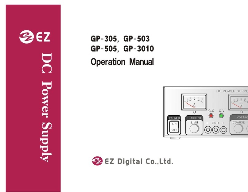
EZ Digital GP-4303D User manual

C. VC. C
DC PO WER SU PPLY G P-4 303 D
3.00 A30.0 V
CU RR EN T FI NE VO LTAGE
PO WE R - GN D +
- GN D +
C. V
C. C
.
DC P OWER SU PPLY GP -43 03A
R
PO WE R
CU RR EN T FI NE VO LTAGE
99 Washington Street
Melrose, MA 02176
Fax 781-665-0780
TestEquipmentDepot.com

INSTRUCTIONS
Thankyouforp urch asi ngE ZD IGI TALp rod uc ts.
Thei nstrumentsp rod uc ed b yE ZD IGI TALarehi g hp rod uc tstec hnp l ogyproducts
madeunderstrictqualitycontrol.
We g u a ra n te e th e i r e xc e p t i o n a l p re c i s i o n a n d u tm o s t r e l i a b i l i ty.
Forproperuseofthisproduct,pleasereadthismanualcarefully.
EZDigitalCo.,Ltd.
1.Tomai ntai nth eprec i si onand th erel i ab i l i tyofth ep rod uc t ,useitinthestandard
setting.
Operatingtemperature:5℃ ~40℃
Operatinghumidity:80%~50%
Storagetemperature:0℃ ~70℃
StorageHumidity:lessthan85%
2.F orq ual i tyi mp rovement, th eexteri ord esi gnand sp ec i fi c ati onsoftheproduct
canbechangedwithoutnotice.
3.Shoul d anyfurth eri nformati onb ereq ui red , p l ea secontacttheEZDIGITAL
companyorsalesoutlet.
WAR R ANTY
Wa rra n ty s e rvi c e c o ve rs o n e ye a r th e d a t e o f o ri g i n a l p u rc h a s e .
Incaseoftechnicalfailureayear,repairservicewillbeprovidedbyEZDIGITAL
company.
We c h a rg e f o r re p a i rs a f te r th e o n e ye a r wa rra n ty p e ri o d e xp i r e s .
Wh e n th e f a i l u re i s a re s u l t o f us e r's n e g l e c t , n a tu ra l d i s a s te roraccident,
wec h arg e forre p ai res re g ard l es s o fth ewarra nty p eri od .
Formoreprofessionalrepairservice,besuretocontactusorsalesoutlet.
[1]

1. I NTROD UCTI ON
GP-4303A/D,4185A/DseriesareregulatedDCPOWERSULLPYunitswithvoltmeter
andamperemeter:GP-4303A/DcansupplytheDCpowerof0to30V/3A
GP-4185A/Dcansupply0to18V/5A.
(AmeansAnalogmeter,DmeansDigitalmeter)
The
y
are
p
rovidedwithcontinuousl
y
variablecoarsead
j
ustmentandtheout
p
utvolta
g
es
andwithcontinuouslyvariablecurrentadjustmentinarangeof10to100%.
Currentlimitingandoverloadprotectionfunctionsarebuiltintoprotecttheovercurrent
.
Thesup p l yfeaturesanl og evol tmeterand amp erem eter, enab l i ngtheusertomonitor
thesupply'soperationataglance.
LEDsforConstantcurrent(C.C)andConstantVoltage(C.V)enablesmonitoringof
operationstatus.
Mai ni np utvol tag eAC115o r230Vsel ec ta b l ea nd 50/60Hzare sup ported.
2.FE ATURE
Builtinoutputcurrentlimitcircuit(OverloadProtection)
Availabilityofseriesand/orparalleloperation
ConstantCurrentandConstantVoltage
LowRipple
RemoteControlOperation(AnalogControlOption)
BuiltinAnalogVoltagemeterandAmperemeter
[3]

3. P RE C AUTI ONS
3- 1.Li nevol tagesel ec ti on
Thi si nstrumentmustbeop erated wi thth ec orrectl i nevol tages electorswitchsetting
andthecorrectlinefuseforthelinevoltageselectedtopreventdamage.
Thei nstrumentop eratesfromei thera90Vto132Vor198Vto250Vl i ne s ourc e.
Beforelinevoltageisappliedtotheinstrument,makesurethelinevoltageselector
switchissetcorrectly.
Inthecaseofthelinevoltageselectorswitchselected,mustbeoperatedtothe
correctlinefuse.
Toc hang eth el i nevol tag esel ec ti on
1.Makes ureth ei ns trumenti sd i sconnec ted from th ep owerso urc e.
2.P ul l outth el i nevol ta gesel ectorswi tc honth ebottompanel .
SelectthearrowmarkpositionoftheswitchfromTable3-1.
Selectthearrowmarktothedesiredpositionandplugitin.
3.P ul l outth el i nefusehol d erc ontai ni ngth efuseforoverl oa dprotection.
Replacethefuseintheholderwiththecorrectfusefromtable3-1&plugitin.
AC90~110
AC108~132
AC198~242
AC207~250
Forcontinuedprotectionagainstfire,replacethelinefuseonlywithafuse
ofthespecifiedtypeandrating.
3- 2. I NSTALLATI ON &HAND LI NG P RE C AUTI ONS
Wh e n p l a c i n g th e p o we r s u p p l y i n s e rvi c e a t yo u r wo rk p l a c e , o b s e r vethefol l owi ng
precautionsforbestinstrumentperformanceandlongestservicelife.
1.Avoi d p l ac i ng th i si nstrumenti nanextremel yh otand col d p l ace.
Specifically,don'tleavethisinstrumentinaclosecar,exposedtosunlightin
midsummer,ornexttoaspaceheater.
Tab l e3- 1.Li nevol tag eSel ecti on&FuseR ati ngs
T1.6A
[4]
GP-4303D/A,GP-4185D/A
T3.15A
230V
115V
SelectSwitchMark FuseRatings(250V)
LineVoltage
!!

2.D on'tuseth i si ns trumenti mmed i atel yafterb ri ng i ti nfrom thecold.
Allowtimeforittowarmtoroomtemperature.Similarydon'tmoveitfroma
warmplacetoaverycoldplace,ascondensationmightimpairitsoperation.
3.D onotexp os eth ei nstrumenttowetord ustyenvi roments.
4.D onotp l ac el i q ui d - fi l l ed c ontai nersontopofthi si ns trum ent.
Aspi llcould seriouslydamagetheinstrument.
5.D onotusethi si nstrum entwh erei ti ssub jec tto servevi ration,orstrongblows.
6. D o no t p l a c e h ea ve ryob je c ts o n th e c a se , o r oth e rwi s e bl o c kth eventilationholes.
7.D onotusethi sp owersup p l yi nstrong m ag neti c fi el d s, suc ha snearmotors.
8. D o n oti ns ert wi re s , to ol s , etc . th ro ug h th e ven ti l a ti o n h o les.
9.D onotl eaveahotsol d eri ng i ronnearth ei nstrument.
10.D onotp l ac eth i si nstrum entfaced ownonth eground , ord a m agetotheknobs
mayresuit.
11. D o n otc o nn ec t oth e rp o wer so urc e to + , - o f th e outp u t term inal.
12.Ground termi nal o fp owerc od emus tconnecttoth eground .
13.Accord i ng tooutp utp orari ty, i tsol ved p rob l em E SD and Fl oa tingvoltageusing
theconnectgroundporttoterminalofoutput.
14.Toc onnectth eground , becareful atg round p orari tyofl oa d.
15.I np utvol tageofi nstrum entmustbeeq ual toACp owervol tag e.
16.I tusetothi ckand sh ortwi reofoutp uttermi na l i np ossi b l e.
3- 3. C LE AR I NG
1.Toc l eanstai ned c asi ng , l i g htl yrub thestai ned a reawi th asoftclothdippedina
neutraldetergent.
2. I f th e s urfa c e of th e p an el i s d i rty, us e th e s a me meth o d to clean.
Ifthepanelisheavilystained,rubtheaffectedarealightywithasoftclothsoaked
inlightneutraldetergentoralcohol.
3.Neverus eh i ghl yvol ati l em ateri al suc has b enzeneorp ai ntthinner.
[5]

4. SP E C I F I CATI ONS
Lessthan0.01%+2mVforpowersourcevoltage
changeof±10%
Morethan10㏁atDC500Vchassisandoutputterminal
Morethan50㏁atDC500VchassisandACplug.
Overloadprotectioncircuitofconstantcurrent
selfrestoringtype
[6]
0~3A 0~5A
PowerConsumption 130VA 130VA
Accessori es Shortci rcuitBar, Manual , Fuse
Powersource AC115/230V,50/60Hz
Dimension 131(W)x150(H)x273(D)
We i g h t Ap p ro x. 4. 5K g
Protectioncircuit
Ambienttemperature 5℃ ~ 40℃
OperatingHumidity 50%~80%
Insulationbetween
Compensation/
±(1%±1d i g i t ) 2. 5%F S
AmpermeteAccuracy
Vo l tm ete r Ac c ura c y
±(1%±1d i g i t ) 2.5%FS
RippleVoltage Lessthan2mVp-p
LineRegulation
LoadRegulation Lessthan0.01%+3mVforloadvariationof0to100%
GP-4185A
Outputpolarity Positive&Negative
Outputcurrent
Mo d el GP - 4303D GP - 4303A GP - 4185D

5. D E C R I P TI ON OFP ANE LF UNC TI ON
5- 1. F ro ntP an el D es c ri p ti on
AnalogType Di gital Type
1. P OWE R SWI TC H : Th i s swi tc h turns o n and o ff th e p o wer.
2. CUR RE NT ME TE R :I nd i c ates th el oa d c urren t
3.VOLTAGE ME TE R:Seta noutp utvol tagewh i l erea d i ng th evol ta geindication.
4. C . C LE D : D i s p l ayLE D fo r overc urrent.
5. C . VLE D :D i s p l a y LE D fo r sta ti c s ta te c urre nt & vol tageop erati ng.
6.CURRE NTVR:The currentl i mi ti ng kno bfors etti ng and a djustingtheoutputcurrentina
rangeofmax.10~100%
7. F I NE VR : Th e fi ne a d jus tme nt kno b o f th e o utp ut voltage.
8. C OAR SE VR : Th e c o ars e ad jus tm en t kn ob of th e o utp u t vo ltage.
9.OUTPUTTE RMI NAL(- ):Th eneg ati vesi d eofoutp uttermi na l .
10.OUTPUTTE RMI NAL(GND ):Whenth ep osi ti vep ol ari tyorneg ati vep ol ari tyi stob ec onnected to
theground,eitheranappropriateoutputterminalshouldbeconnected
totheGNDbyashortcircuitbarsuppliedasaccessory.
Wh e n n o b a r c o n n e c ti o n i s m a d e , th e te rm i n a l i s u s e d a s th e g ro u n dterminal
11.OUTPUTTE RMI NAL(+):Th ep osi ti ves i d eofoutp uttermi nal .
[7]
③
②②③
⑤
⑤
⑥⑥
⑧
⑧⑦
⑦
①①
④
⑪
④
⑬⑨⑩⑬⑨⑩⑪
-GND+
CURRENTFINEVOLTAGE
C.VC.C
DCPOWERSUPPLYGP-4303D
3.00 A30.0
V
POWER
ON
OFF
C.C
-GND+
CURRENTFINEVOLTAGE
POWER
ON
OFF
DCPOWERSUPPLYGP-4303A
C.VC.C

6.OPERATIONS
6-1INDEPENDENTOPERATION
(1)The(+)terminalorthe(-)terminalistobeconnectedalwaystotheGND.
Terminal(GND)withshortcircuitbarasanaccessor
y
shouldbeconnectedasshowni
n
Fig6-1.
Whenpositiveoutputpolarityisrequired.
-GND+
SHORTCIRCUITBAR
(2)ConnecttheACPowercordtothepowersourceofthespecifiedvoltage,andturnon
thepowerswitch.
(3)Tosettheloadvoltage,slowlyturnthevoltageadjustingknob(5)caorseclockwise
withnoload,whilewatchingtheamperemeter.
Theknob(5)isforcoarseadjustment,andtheknob(4)isforfineadjustment.
(4)Loadcurrentsettingisusedforlimitingthecurrentappliedtoadevicetobetestedat
aspecifiedpowerortoprotectthedevicefromtheovercurrent.
Tosetthecurrent,connectthe(+)and(-)terminalabyathickleadwire.
Slowlyturnthecurrentadjustmentknob(3),andsetthecurrentwhilewatchingthe
amperemeterindication.
Atthistime,setthevoltageadjustmentknob(5) f u l l c o u n te r c l o c k wi s e a n d s e t th e
whitemarkoftheFINEadjustmentknob(4)atmiddle.
Theminimumcurrentthatcanbesetisasfollows.
GP-4303D/A:Approx.200mA~3A GP-4185D/A:Approx.350mA~ 5A
Aftersettingalimitingcurrent,removetheshortcircuitwire.
Thensetthevoltagetoarequiredvoltagelevel.
(5)Aftercompletingtheaboveprocedure,watchthepolarityofadevicetobeapplied
andusetheinstrument.
Ifthevoltmeterindicationbecomeslessthanthessetlevelforadefectofadeviceto
betestedorforanyotherreason,theovercurrentprotectioncircuitisactivated,
resultinginswitchingintotheconstantcurrentoperationfromtheconstantvoltage
operation.
Whentheinstrumentistobeusedintheconstantvoltageoperatingcondition,setthe
currentadjustmentknobfullclockwise.
Inthiscasetheshortcircuitcurrentis3A+10%fo rth e GP - 503, 5A +10% for th e
GP-305/505,and10A+5%fortheGP-3010.
Fig.6-1
[8]

6-2SERIESOPERATION
(1)Byconnectingacoupleoftheunitsinseriesahighervoltagethanasingleunitis
available.Insuchacase,noterminalshouldbeappliedwithavoltagemorethan
theratingvoltageagainstthegroundpotentialbetweenaterminalandpanelchassis.
Therati ngvol tageag ai nstth eg round i s±100V.
Wi th a s e ri e s o p e ra ti o n o f c o u p l e o f th e u n i ts , a d o u b l e o f th e ratingvoltageofasingle
unitandcurrentofasingleunitsisavailable.
Wh e n two u n i t , e i th e r G P - 4303A/D a re u s e d th e m a xi m u m vo l ta g e a va ilable+60Vor-60V.
Wh e n two u n i t , e i th e r G P - 4185A/D a re u s e d th e m a xi m u m vo l ta g e a va ilable+36Vor-36V
NOTE:1.Theovercurrentprotectioniseffectiveatthesmallervalueofthetwo.
2.Seriesoperationbetweenothertypesisnotavailable.
(2)Notesonseriesoperation
WhentheseriesconnectedtwounitsofregulatedDCpowersuppliesareoverloaded,
theunitinwhichtheovercurrentprotectioncircuitactivatedfirstisappliedwiththereverse
voltagefromtheoutputoftheunit,andsotheseriescontrolelementoftheformerwillbe
damaged.
Top rotec tth i sp rob l em, c onnec ttwod i od esb etweenth eoutputte rminalsoftheunitsas
showninFig.6-2
Diodestobeusedshouldbewiwthahighvoltageeethanthemaximumratingvoltageof
asingleunit,andthevoltageratingofsiosesshouldbe2to3timesofthemaximum
vol tageoftheseri esconnecti on.
(+)
(-)
(+)
(-)
(3)Connection
-GND+ -GND+
(-) (+)
(a ) F o r th e n e g a ti ve g ro u n d i n g : As s h o wn b y a s o l i d l i n e fi g . 6- 3
(b ) F o r th e p o s i ti ve g ro u d i n g : As s h o wn b y a d o tte d l i n e f i g . 6- 3
DonotconnecttheGNDterminaltodifferentpolaritiesotherthanfig.6-3
Fig.6-2
Fig.6-3
[9]
L
O
A
D
LOAD

6-3PARALLELOPERATION
(1)Whenacurrentcapacitylargerthanasingleunitisrequired,acoupleoftheunitsmaybe
usedinaparallelconnection.
Inaparalleloperation,aunitbecomesthemainunitandotherbecomesthesub-unit.
Settingofthevoltageandcurrentshouldbemadeofthemainunit.
(2)Connection
Maketheconnectionwhilethepoweroff.
-GND+ -GND+
(main) (sub)
Forparalleloperatio,.maketheconnectioninthesequenceofthe(+)terminalofthemainunit,(+)
terminalofthesub-unit,(-)terminalofthemainunit,and(-)terminalofthesub-unit.
ThenconnectthewiresbetweentheParallelterminal(mainunit)andtheParallelterminal(subunit)
Usethickwiresforalltheconnections.
(a)Turnthevoltageknob(5),(4)andthecurrentknob(3)ofthesubunitfullclockwise.
(b)Thevoltageandcurrentarevariablebythemainunit.
Theoutputcurrentlimitcanbeselectedwithinarangeofabout10to100%ofthe
doubleofthemaximumratingcurrent.
Inthiscase,astheloadcurrentincrease,theamperemetersofbothmainandsubunits
swing,andtheloadcurrentisindicatedasthesumofbothamperemeters.
NOTES:OthertypeofregulatedDCPowersupplycanbeconnectedforparalleloperation.
Themaximumnumberofunitsforparalleloperationislimitedto2units.
7.NOTESONENVIRONMENTALCONDITION
7-1.Avoidusingtheunitinsuchaplacewheretheambienttemperatureexceeds40℃ orunder
thedirectsumshines.
Limitthemaximumoutputcurrentwhentheunitisusedinsuchaplacewhereventilationis
interruptedoraradiationexistsotherequipments.
7-2.Usetheinstrumentwhitin10%toleranceofthespecifiedfrromthepowersource.
Fig.6-4
[10]
LOAD

8. C UR RE NTLI MI TI NGC I RC UI T
Wh e n th e o u tp u t t e rm i n a l s a r e s h o r t c i rc u i t e d b y m i s t a k e , th e c u r rentlimitingcircuitis
activatedtolimittheflowofthecurrentinexcessoftheratingoutputcurrent,sothatthe
controlelementsandtheamperemetersconnectedinseriesoperationanbeprotected
fromthesuddendamage.
Theoutputl i mi tcurrentcaanbeseti narangefrom10to100% oftheratingcurrent,and
wh en th e ou tp utc u rre nt rea c h es th e se tval ue, th ei n strum en to p e ratesintheconstant
currentcondition.
Astheoutputcurrentcomesdownbel owthesetvalue, theconstantvoltageconditionis
automaticallyresumed.
9.TOR E PLAC E THE FUSE
PulloutF1belowwithscrewdriverandgetridofF1,takeoutspareFuseintheholder
PutitinthepositionofF1.
Fuse(F1)
SPAREFUSE
[11]
Turnoffth ep owerswand
removethepowercord,
changetheabnormalfuse
!
This manual suits for next models
3
Table of contents
Other EZ Digital Power Supply manuals
Popular Power Supply manuals by other brands

Pentair
Pentair C20 installation guide

Recom
Recom RACM60-K/277/OF Installation and operating instructions

Helios
Helios KWL-KS WE Installation and operating instructions

PowerBox Systems
PowerBox Systems Mercury SRS instruction manual

Altronix
Altronix AL400UL3 installation guide

Helios
Helios SR250HL user manual