4
|
nVent.com/ERICO
Installation and Operating Instructions
• Transient protection devices are usually rated to protect
against non-repetitive pulses from sources such as direct or
induced lightning energy.
• They are not designed to provide protection against repeated
cyclic anomalies such as those caused by motor speed
control notching (variable speed controls, etc).
• SRFs are not designed to provide protection against
sustained over-voltage conditions where the supply voltage
exceeds, for an extended period of time, the nominal rating of
the protection equipment. i.e continuous over-voltages from
poorly regulated generators or distribution systems.
• Smaller power generation equipment does not always
conform to the same standards of voltage regulation that
is in place for mains power reticulation. A large number of
smaller or cheaper generators have a voltage waveform that
approximates 240Vrms (often poorly regulated), but more
importantly, which often contains significant higher order
harmonics and may exhibit a peak voltage on each half cycle
far in excess of the normal 340V (peak). Such machines
are usually capacitive excitation induction generators, as
opposed to synchronous generators. The problem is usually
increased when the generator is lightly loaded.
• Harmonic voltages may also be present in distribution
systems that do not feature generators. This is normally
where non-linear loads are used, such as UPSs, rectifiers,
switch-mode power supplies and motor speed controls. The
harmonic voltages may have peak voltages in excess of the
protective clamping voltages, causing problems such as
excessive heat build up. Because the harmonic waveforms
contain higher order frequencies, capacitive leakage currents
may increase to above prescribed limits and shorten the
life of the SRF. It should be noted that in sites with large
harmonic voltage distortion, the SRF capacitance may
dramatically affect the power factor.
• Seek the manufacturers ' advice before installing any SRF
into a circuit which features a total harmonic voltage ratio
above 5%.
• With large transients, significant energy may be passed by
the SRF diverters back to the source or to earth. This may,
under some circumstances, cause upstream earth leakage
circuit breakers or residual current devices (ELCBs & RCDs)
to nuisance trip. Where possible, these devices should be
installed after the SRF in order to reduce this possibility.
• Transient protection devices often have minimum
requirements for upstream fusing to ensure proper operation.
See section 6.1 for fusing requirements.
• By-pass switches are not recommended to be used with
SRFs as they compromise the protection offered. The
connection of the by-pass switch compromises the input to
output separation requirement by bringing the SRF input
and output wiring into close proximity at the switch.
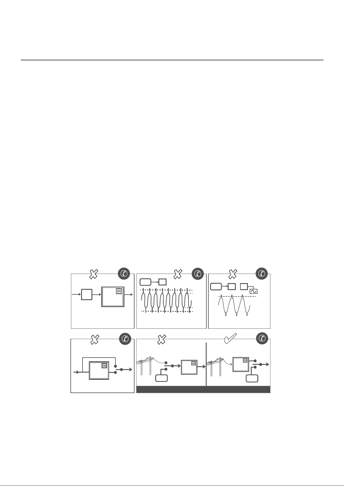
3 INSTALLATION CAUTIONS
Figure 1. Seek specialist advice with the above installations.
SRF
SRF
SRF
SRF SRF
ELCB
or
RCD
NON PREFERRED NON PREFERRED PREFERRED
AVOID UPSTREAM EARTH LEAKAGE CIRCUIT BREAKERS
(ELCB’S) OR RESIDUAL CURRENT DEVICES (RCD’S)
BYPASS SWITCHES
BYPASS SWITCHES COMPROMISE PROTECTION
AVOID REPETITIVE VOLTAGES IN EXCESS OF SRF RATING AVOID HIGH HARMONIC VOLTAGES
276 Vrms
Or
276 Vrms
276 Vrms
240 Vrms
240 Vrms
GENERATOR
GENERATOR
GENERATOR GENERATOR
SRF SRF
MAINS / GENERATOR CHANGE OVER SWITCH CONNECTION