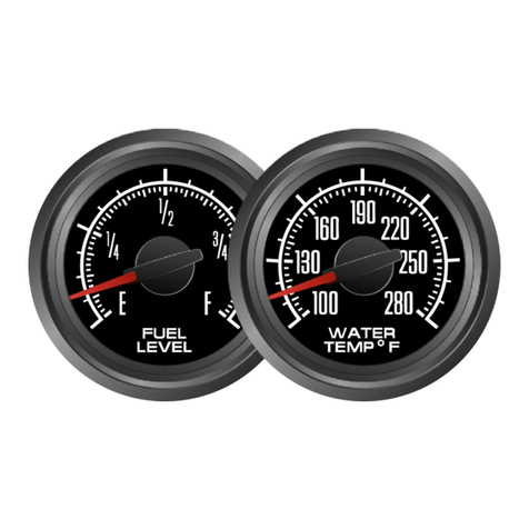
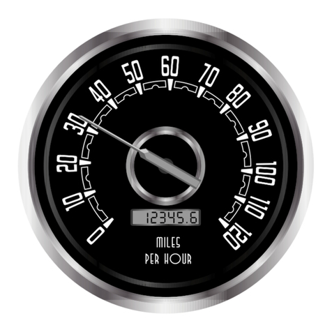
NVU Detroit User manual

PROGRAMMABLE DIESEL TACHOMETER
INSTRUCTION BOOKLET
REV 032120

This page left blank

THE BACK OF YOUR GAUGE PROGRAMMABLE WITH OLED SCREEN AND PORTS
All programmable speedometers and tachometers with an OLED screen of any size are
master gauges that can drive minor functions. The minor gauges are driven directly by the
master and no additional connections are required.
DIP SWITCHES:
Used to adjust fuel range on
speedometers. See fuel gauge
chart later in this booklet. Remove
the black plastic cover to access this
if needed. See DIP switch settings
later in this booklet
AMP PLUG SOCKET :
USE the NVU universal AMP plug and wire as
shown in the proper diagram. NVU uses the
same plug for all gauges so some wires may
not be used in your application.
LIGHT SOCKETS:
The sockets hold NVU bright white
LED 194 bulbs. They are
replaceable if needed. If you need
to replace a bulb, the LEDs are
polarity sensitive and have to be
installed properly to operate. If
you find the bulb will not light,
turn it 180 degrees and reinstall.
LEDS are not dimmable using a
standard dimmer. Wire into your
parking lamp circuit and use an
LED dimmer if required
DRIVER SOCKETS:
This applies to 5 and 6 gauge kits with NVU PNP technology. 2, 3 and 4 gauge kits will not
use the driver features. Refer to each wiring diagram. Plug the appropriate gauge into
the socket and it will function through the master driver unit.
The B, C and D pins are used to connect the 2-1/16” gauges through the master gauge.
All functions and lighting are done through this plug. Refer to the wiring diagram for each
kit for proper wiring. Below is each plug’s function and its corresponding input wire
color. Pins C and D are the same on the speedo and tach.
SPEEDOMETER:
B: PROGRAMMABLE FUEL (GREEN WIRE) Connects to your fuel sender. The input is
programmable, please see the fuel gauge DIP switch settings on page 34
C: WATER TEMPERATURE (YELLOW/GREEN WIRE) Connects to the NVU temperature
sender.
D: OIL PRESSURE (YELLOW WIRE) Connects to NVU pressure sender .
TACHOMETER:
B: VOLTS No input wire required, internal to gauge
C: WATER TEMPERATURE (YELLOW/GREEN WIRE) Connects to the NVU temperature
sender.
D: OIL PRESSURE (YELLOW WIRE) Connects to NVU pressure sender .

6 GAUGE KIT PROGRAMMABLE SPEEDO AND TACHOMETER
WITH OLED SCREENS
MASTER GAUGE WIRING
All programmable speedometers and tachometers with an OLED screen of any size are
master gauges that can drive minor functions. The minor gauges are driven directly by the
master and no additional connections are required. Wire as shown below and plug the
minor gauges into their appropriate plug (B,C,D) on the back of the master gauge.
123456
7 8 9 10 11 12
12-PIN AMP PLUG
PLUG #174045-2
PIN #173681-1
TEMP SEND
PRESS SEND
SPEEDOMETER
TEMP/FUEL TACHOMETER
VOLT/PRESS
REMOTE BUTTONS ONE SIDE
TO SPEEDO, ONE SIDE TO
GROUND. MOMENTARY ON
GROUND
BATTERY IGNITION FUSE BLOCK
LIGHT SWITCH
DIMMER FUEL SEND
PCM/CDI
TYPICAL 3-WIRE
SPEED SENDER
TYPICAL 2-WIRE
SPEED SENDER,
VSS, ECU OUTPUT
BLACK-CHASSIS GROUND
RED- 12V SWITCHED
WHITE OR GREY
TO SPEEDOMETER
SIGNAL INPUT
PCM/GPS
PIN COLOR FUNCTION
1 RED 12V+ SWITCHED 1A
2 GR/YEL TEMP SENDER
3 ORANGE SPEED SIGNAL
4 YELLOW AUX 1
5 TAN HI BEAM 12V+
6 WHITE LIGHTING
7 BLACK GROUND
8 VIOLET NOT USED
9 GREY RED WARN 12v+
10 BLUE LEFT TURN 12V+
11 GREEN FUEL
12 BROWN PROG BUTTON
PIN COLOR FUNCTION
1 RED 12V+ SWITCHED 1A
2 GR/YEL AUX1
3 ORANGETACH SIGNAL
4 YELLOW OIL PRESS
5 TAN WARNING 12V+
6 WHITE LIGHTING
7 BLACK GROUND
8 VIOLET NOT USED
9 GREY GLOW PLUG 12V+
10 BLUE CHK ENGINE 12V+
11 GREEN AUX2
12 BROWN PROG BUTTON
MAGNETIC
PICKUP
ALTERNATOR
W TERMINAL

MINOR GAUGE WIRING 6 GAUGE KIT
All programmable speedometers and tachometers with an OLED screen of any size are
master gauges that can drive minor functions. The minor gauges are driven directly by the
master and no additional connections are required. Wire as shown below and plug the
minor gauges into their appropriate plug (B,C,D) on the back of the master gauge.
Follow the diagram below to properly plug the minor gauges into the master units.
.
The B, C and D pins are used to connect the 2-1/16” gauges through the master gauge.
All functions and lighting are done through this plug. Refer to the wiring diagram for each
kit for proper wiring. Below is each plug’s function and its corresponding input wire
color. Pins C and D are the same on the speedo and tach.
SPEEDOMETER:
B: PROGRAMMABLE FUEL (GREEN WIRE) Connects to your fuel sender. The input is
programmable, please see the fuel gauge DIP switch settings later on page 34
C: WATER TEMPERATURE (YELLOW/GREEN WIRE) Connects to the NVU temperature
sender.
TACHOMETER:
B: VOLTS No input wire required, internal to gauge
D: OIL PRESSURE (YELLOW WIRE) Connects to NVU pressure sender .
SPEEDOMETER
TEMP/FUEL TACHOMETER
VOLT/PRESS
C: TEMPB: FUEL
SET RANGE ON SPEEDO
DIP SWITCHES
B: VOLT D: PRESS

PROGRAMMABLE TACHOMETER WIRING
Standalone tachometers with AMP plugs are incandescent perimeter, backlit or
LED backlit. Incandescent bulbs will be in the access holes installed into the circuit
board. DIP-switch settings are not required on tachometers . 3-3/8” and 4-3/8” are
the same configuration.
123456
7 8 9 10 11 12
12-PIN AMP PLUG
PLUG #174045-2
PIN #173681-1
TACHOMETER
VOLT/PRESS
REMOTE BUTTONS ONE SIDE
TO SPEEDO, ONE SIDE TO
GROUND. MOMENTARY ON
GROUND
BATTERY IGNITION FUSE BLOCK
LIGHT SWITCH
DIMMER PCM/CDI
PIN COLOR FUNCTION
1 RED 12V+ SWITCHED 1A
2 GR/YEL AUX1
3 ORANGETACH SIGNAL
4 YELLOW OIL PRESS
5 TAN WARNING 12V+
6 WHITE LIGHTING
7 BLACK GROUND
8 VIOLET NOT USED
9 GREY GLOW PLUG 12V+
10 BLUE CHK ENGINE 12V+
11 GREEN AUX2
12 BROWN PROG BUTTON
MAGNETIC
PICKUP
ALTERNATOR
W TERMINAL

INSTALLATION BASICS:
-Use a minimum of 20 gauge insulated, stranded wire, all connections should
be connected with a crimp connection or solder and heat shrink.
-Keep speed signal wire(s) away from potential “noise” sources like ignition
wires, tach signal wires, fan motors, pumps etc.
-Studded speedometers use #8 studs, use applicable eye terminals for wiring.
-Use a maximum of 5A fuse for the entire cluster, this is usually already in your
fuse block
Commonize wiring, ground, power and lights can be common on all gauges and
“daisy chained”
OLED DISPLAY TACHOMETERS WITH ANALOG POINTERS
With all of the features packed into NVU Phoenix platform tachometers, we
have divided them into different menus. Your tach has a main “RUN”
Menu, and a “SETUP” menu. The RUN menu utilizes the features used during
normal operation. The SETUP menu stores all of the items that are setup
during the installation process. Items can be changed any time after, if desired,
and are separate to prevent inadvertently changing them during normal use.
RUN Menu Functions
Features can be accessed in the run menu during normal operation with the key
on. To scroll to the various displays in the OLED screen, use a short push or
tap of the remote button.
BLANK SCREEN: We have included a blank screen option to give the user an
opportunity to not display any information.
HOURMETER: Displays the total hours the vehicle has been running. This is
not resettable. This function is useful to track servicing the vehicle especially
when idling for long periods is common such as in commercial, fleet and
emergency vehicles, or when a speedometer or odometer is not used in the
vehicle.

RUN MENU-CONTINUED
SERVICE HOURS: User resettable hourmeter to track engine use similar to a
trip odometer. It is identified by the SH on the left side of the screen
This can be reset just like a trip odometer, while in this screen hold down the
set button until zero is displayed. The hours will count up from there. This can
be reset at any time and can also be used for tracking time to a destination as
well as servicing the vehicle.
PEAK RPM is displayed on the following screen. This will store and allow the
user to view the peak RPM achieved since the last reset.
This can be reset any time by holding in the programming button until all zeros
are displayed. This may be reset at any time and the last peak RPM will be
stored until reset.
BOOT or SETUP MENU. This area of the tachometer is used during set-up
and any of the settings can be changed at any time. The items in the setup
menu are “hidden” in this sub-menu to avoid inadvertently changing settings
during normal use. To enter the setup menu, hold in the button while turning
on the key (you do not have to start the vehicle if you do not want to). The
setup menu screen will be displayed. To exit the setup menu, turn the key off,
and restart normally.

BOOT MENU, CONTINUED
MANUAL CALIBRATE: Allows the user to set the tachometer to accommodate
different number Pulses received from the input source. It is selectable from 2-
180 PPR (pulses Per revolution). To enter manual calibration mode, enter the
setup menu and scroll to MANUAL CALIBRATE
To set the number of PPR, Tap the button to advance the digit. Hold the button for
1 second to advance to the next digit and repeat the process. At the end of the
last digit, hold the button until Y/N appears. Select Y for yes, No for no. A
successful programming will appear with your set PPR and SAVED! You must
restart the unit for settings to take effect.
INPUT FILTER. Generally this setting does not require and adjustment. You may
change the settings if you are having difficulty with noise in your signal or sharp
spikes. To enter the filter mode, hold in the button until the settings are shown.
There are 3 options low “L” medium ”M” and high “H”. You can experiment to see
if the filters aid your signal. The changes can be made with the vehicle running so
you can see the difference in settings.
To change the setting, scroll to L, M or H and hold in the button. Once you are at
the desired setting, hold in the button until the confirmation message is displayed,
and select Yes or NO, hold in the button to select. SAVED! will confirm the setting
has been changed and now the filter is set.
SHIFT ALERT. The shift alert is built-into the OLED display and will give the driver
a warning of when to shift based on RPM. The alert is a 3 stage display, warning
1,000 and 500 RPM before the shift point, and the actual shift point. This can be
used to pre-set shift points for optimal horsepower, mileage or to prevent over-
revving the engine, it is up to the driver to decide how they would like it to be set
up. The shift alert can also be disabled by setting to zero RPM.

BOOT MENU, CONTINUED
SHIFT ALERT, CONTINUED. To enter the shift alert menu, hold in the button
while at the screen.
The current shift point will be displayed (0000 for no shift alert). Tap the button to
change the first digit which will be highlighted. Each tap will advance the digit by
one number.
Hold the button in to advance to the next digit and follow the same sequence until
you have the desired setting.
At the last digit, once satisfied, hold in the button to enter the verification menu.
Select YES or NO and hold in the button. Once saved, the display will show the
current shift setting and SAVED!
HOW THE SHIFT ALERT DISPLAYS INFORMATION: This is active all of the
time when in any menu window during normal operation. For the setting above,
5,500 RPM, the display with indicate the engine is 1,000 RPM before the shift
point with a single arrow on the screen:
500 RPM before the shift point 2 arrows will be displayed:
At the desired, set shift point, the screen will invert creating a highly visible sign
that the engine is at the RPM designated to shift, the word SHIFT will display:
The arrows will operate in the inverse as RPM decreases. The shift point setting
can be changed at any time desired, or disabled by setting the shift alert to all
zeros (0000).
PROGRAM VERSION. This displays the current software version installed in the
unit.

This page left blank

THANK YOU
Thank you for choosing NVU products. We strive to provide the finest quality
and designed products available on the market.
TECH SUPPORT
DO NOT contact the retailer for tech/installation assistance. The retailer will not
have the technical expertise to know the contents of the kit or the nuances of
installing in your specific vehicle. We are here to help!
Contact NVU directly, our qualified installation technicians have the knowledge
of the product and its installation to help you get going right away.
If you need technical assistance please feel free to call us at 248.850.5482 or
email us at service@newvintageusa.com
NVU 5-YEAR WARRANTY
Service can be obtained during the normal warranty period by contacting New
Vintage and obtaining a Return Authorization Number (RZA#). New Vintage will
repair or replace any item found to be defective and return ship to no cost via
ground or post office services. Other shipping/international services will be
applied at additional cost. Buyer is responsible for shipping to New Vintage for
warranty repair. Return shipping will be the responsibility of the customer if the
product is found to be damaged or out of warranty. An RZA number must be
obtained and proper return/warranty form accompanied with the product.
MISSING ITEMS/RETURNS
Hey, we all make mistakes, no problem just give us a call if you believe that you
are missing something in the box. DO NOT CONTACT THE RETAILER, as
they will not have the complete packing list or the pertinent information to
properly help you. We will take care of it for you.
Missing items/returns must be processed within 15 days of end user receiving
the product. All returned must be shipped back to the place of purchase. Any
return shipping costs to New Vintage are the responsibility of the purchaser. An
RZA number must be obtained and proper return/warranty form accompanied
with the product. A restocking fee not to exceed 10% may be applied to items
that must be repackaged. Any item returned in a non-usable condition will be
returned or charged to the customer.
Missing items must be reported within 15 days of receiving the product. Items
found to be missing will be shipped via ground or postal service at no charge.
Expedited/international shipping options are available at an additional charge. It
is the policy of New Vintage to quickly replace any items that may be missing in
a timely manner but not to overnight or expedite shipping in any way at no cost.
Table of contents
Other NVU Automobile Accessories manuals
Popular Automobile Accessories manuals by other brands

Havis-Shields
Havis-Shields 2004-2008 Ford Econoline Van C-VS-1800-ECO Install instructions

Directed
Directed VW02 Firmware Specific Guide

Voxoa
Voxoa MCU-20A(P40) user manual

Mont Blanc
Mont Blanc FK161 Fitting instructions

Phonocar
Phonocar VM342 Mounting instructions

Phonocar
Phonocar 5/928 Mounting instructions