NXP Semiconductors TED-Kit 2 User manual

UM10276_1
TED-Kit 2
Rev. 1.29 —20 August 2010
User manual
Document information
Info
Content
Keywords
TED-Kit 2, HITAG, Immobilizer, PKE, RKE
Abstract
The purpose of this document is to describe how to install and use the
TED-Kit 2 and its GUI software. The intended audiences are engineers
planning to use the TED-Kit 2.

NXP Semiconductors
UM10276_1
TED-Kit 2 User Manual
All information provided in this document is subject to legal disclaimers.
© NXP B.V. 2010. All rights reserved.
User manual
Rev. 1.29 —20 August 2010
2 of 79
Contact information
For additional information, please visit: http://www.nxp.com

NXP Semiconductors
UM10276_1
TED-Kit 2 User Manual
All information provided in this document is subject to legal disclaimers.
© NXP B.V. 2010. All rights reserved.
User manual
Rev. 1.29 —20 August 2010
3 of 79
1. Introduction
The purpose of this document is to describe how to install and use the TED-Kit 2 and its
GUI software. The intended audiences are engineers planning to use the TED-Kit 2.
Section 2 gives a very brief system overview to explain all the terms used throughout this
manual.
Section 3 describes in detail what requirements the host system must meet to use the
TED-Kit 2 software and hardware, how to install the software and how to remove it after-
wards.
Section 4 gives a quick-start in 5 simple steps to authenticate with a HITAG 2 trans-
ponder and show the content of its EEPROM.
Section 5 introduces the GUI and shows how to accomplish common tasks like configur-
ing the base station and interacting with a transponder IC.
Section 6 describes all elements of the user interface in detail; it may be used as a refer-
ence.
Section 7 describes some tips & tricks and how to deal with operation errors.
Section 8 shows the PCBs and schematics of the TED-Kit 2 hardware.
2. System overview
This chapter will give a brief system overview to explain all the terms used throughout
this manual.
The TED-Kit 2 system consists of hardware and software used to evaluate and demon-
strate the base station and transponder functionality of NXP devices. Fig 1 illustrates all
major components of a typical system setup.

NXP Semiconductors
UM10276_1
TED-Kit 2 User Manual
All information provided in this document is subject to legal disclaimers.
© NXP B.V. 2010. All rights reserved.
User manual
Rev. 1.29 —20 August 2010
4 of 79
Fig 1. System Overview
The host PC running the TED-Kit 2 software connects with the TED-Kit 2 box via USB.
One or two external LF antennas are connected (depending on the internal configura-
tion). Via the antenna, the TED-Kit 2 box exchanges data with the transponder IC found
in e.g. a key.
The TED-Kit 2 box itself has 4 so called XSlots. Each of them can take one XBoard con-
taining actual functionality like e.g. an ABIC1 base station IC. On one side of the box, the
USB connector and the external power supply can be found. The later is used if the
XBoards require extra power which cannot be delivered by the USB port. Besides that, a
power and a data indicator can be found. The first lights as soon as power is available
and the TED-Kit 2 box can be used, the second lights if data are transmitted to or from it
via USB.
On the opposite side of the TED-Kit 2 box, the two antenna plugs for LF antenna #0 and
#1 can be found. Aside of them, 4 LED indicators are located used for several different
purposes (e.g. to indicate some status or error condition). Next to the LEDs, 2 buttons

NXP Semiconductors
UM10276_1
TED-Kit 2 User Manual
All information provided in this document is subject to legal disclaimers.
© NXP B.V. 2010. All rights reserved.
User manual
Rev. 1.29 —20 August 2010
5 of 79
are found which can be used by the firmware of the TED-Kit 2 box (they have no function
yet).
2.1 Supported applications and hardware
The table below shows the supported applications and the hardware required by the
TED-Kit 2 system:
Table 1. Supported applications and hardware
Application
Hardware
Transponder
XBoards
ID
Example
LF
UHF
Immobilizer
HITAG2
A
PCF7936A
ABIC1
n/a
HITAG2+
A
PCF7946A
HITAG2+EE
A
PCF7947A
HITAG2-Extended
E
PCF7937EA
HITAG3
X
PCF7961X
HITAG-Pro
P
PCF7939P
HITAG-Pro 2
V
NCF2950V
Remote Keyless Entry
RKE
PCF7945A
LoPSTer
Passive Keyless Entry
PKE
PCF7952A
3. Setup
This chapter will explain the necessary system requirements for the TED-Kit 2 software
and hardware as well as how to install and remove the software.
3.1 System requirements
The computer system used as host for the TED-Kit 2 software and hardware must meet
the following requirements:
1. It must run Windows XP. Although it is expected that Windows 2000, Vista and 7 will
work also, these systems are not tested and not supported.
2. For each TED-Kit 2 box, a free USB (Version 2) port must be available on the host
PC. Although it is expected that USB V1 or V1.1 ports will work also, this is not
tested and thus, not supported.
3. The screen size shall be at least 1024 x 768 pixels. Although the software will run on
screens with lower size, it is not recommended because the use of GUI and its forms
will become less convenient.
4. Software to show Adobe PDF documents shall be installed on the system to be able
to read the documentation and the data sheets.
5. The user account used to install the software must have administration rights (due to
device driver and system component installation procedures).
3.2 Installing the software
Note: To avoid any conflicts with previous versions of this software, it is recom-
mended to remove them before continue installing a new version.

NXP Semiconductors
UM10276_1
TED-Kit 2 User Manual
All information provided in this document is subject to legal disclaimers.
© NXP B.V. 2010. All rights reserved.
User manual
Rev. 1.29 —20 August 2010
6 of 79
The installation process is quite simple. Insert the media containing the TED-Kit 2 Setup
software in the host PC and run Setup.exe. The installer will guide the user through the
installation process.
Before starting the software for the first time, please install the hardware (see section 3.3,
page 6).
Note: To read the documentation and the data sheets, proper PDF reader software
is required. Please make sure your system contains such software, e.g. Adobe’s
PDF Reader (available for free from Adobe).
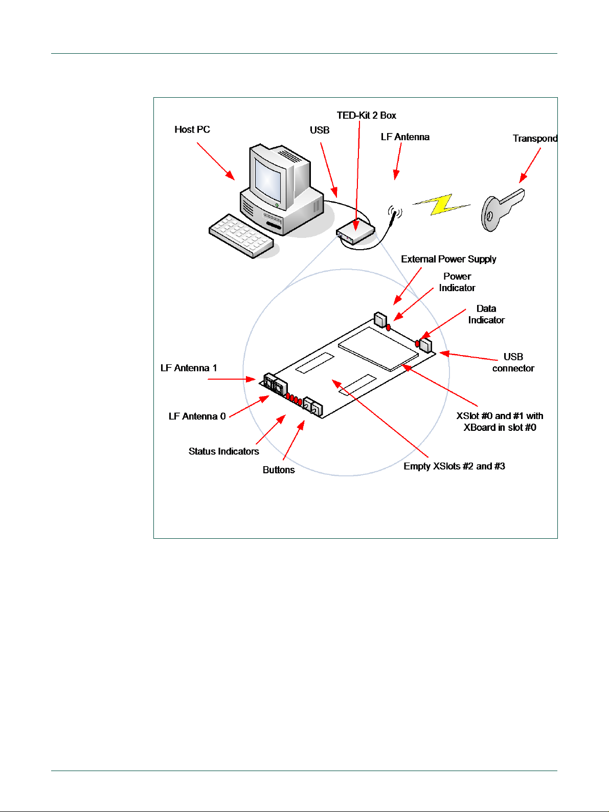
3.3 Installing the hardware
Usually, the hardware comes ready to use with everything installed already. In case the
XBoard is delivered separately, it must be installed in the TED-Kit 2 board first:
1. Open the TED-Kit 2 box removing 4 screws (2 at each front side).
2. Plug the ABIC1 XBoard in the XSlot #0 of the TED-Kit 2 main board. XSlot #0 can be
found on the main board; a label says Extension slots 0 and 1. It is the one closer to
the USB and power supply plugs. It might be necessary to open the TED-Kit 2 box
first.
3. Plug the antenna in port LF0. Port LF0 is the antenna port closer to the 4 status
LEDs.
4. Plug the USB cable in the USB port of the TED-Kit 2 and the host PC.
5. The Windows Hardware Wizard will pop-up and ask for the appropriate driver. Point
it to:
[TED-Kit 2 Installation Folder]\Device Driver
6. The Hardware Wizard will finish the driver installation.
3.4 Removing the software
To remove the software from the PC, the standard procedure of the Windows operating
system shall be used. It will delete all software components as well as the installed driver
software, manuals and (if installed) the software development components.
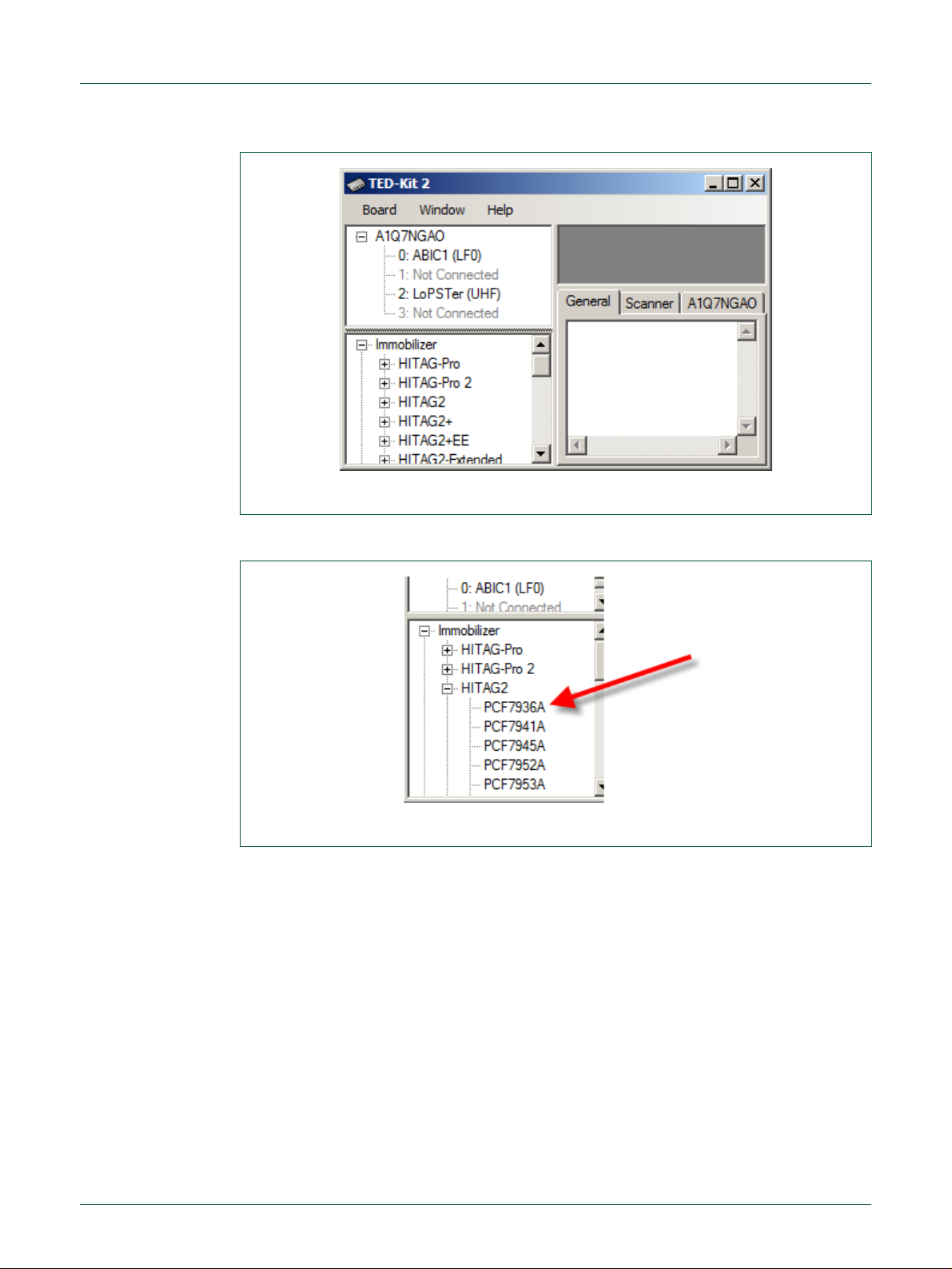
4. Quick start
This section shows how to connect with a transponder, authenticate and read out its
EEPROM content very briefly. It will not give any detailed explanations. To walk through
the steps, the software must be already successfully installed. The PCF7936AS (HI-
TAG 2) transponder used in this example must be configured to do authentication in plain
mode with the default settings and passwords.
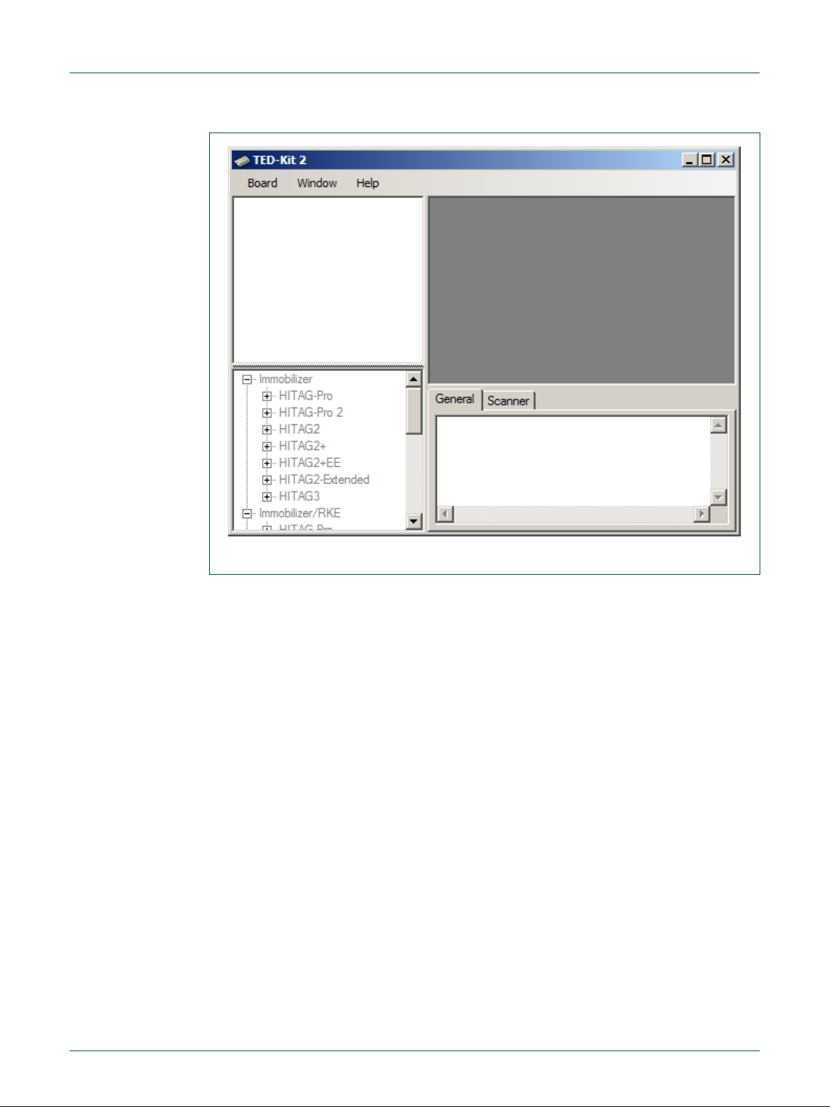
1. Start the GUI via (Fig 2):
S
St
ta
ar
rt
t
A
Al
ll
l
P
Pr
ro
og
gr
ra
am
ms
s
N
NX
XP
P
S
Se
em
mi
ic
co
on
nd
du
uc
ct
to
or
rs
s
T
TE
ED
D-
-K
Ki
it
t
2
2
V
V3
3
T
TE
ED
D-
-K
Ki
it
t
2
2

NXP Semiconductors
UM10276_1
TED-Kit 2 User Manual
All information provided in this document is subject to legal disclaimers.
© NXP B.V. 2010. All rights reserved.
User manual
Rev. 1.29 —20 August 2010
7 of 79
Fig 2. TED-Kit 2 main window
2. Expand the H
HI
IT
TA
AG
G
2
2node of the I
Im
mm
mo
ob
bi
il
li
iz
ze
er
rtree in the applet view and double-click
P
PC
CF
F7
79
93
36
6A
Ato open the Immobilizer applet form (Fig 3).
Fig 3. HITAG 2 immobilizer selection
3. Click the S
St
ta
ar
rt
tbutton to start the immobilizer applet form popping up (Fig 4).

NXP Semiconductors
UM10276_1
TED-Kit 2 User Manual
All information provided in this document is subject to legal disclaimers.
© NXP B.V. 2010. All rights reserved.
User manual
Rev. 1.29 —20 August 2010
8 of 79
Fig 4. HITAG2 authentication starting
4. The immobilizer applet runs and authenticates the transponder with the default
communication and authentication settings (Fig 5).
Fig 5. HITAG 2 authentication running
5. Click the
E
EE
EP
PR
RO
OM
M…
…button to open the memory window and see the content (Fig 6).

NXP Semiconductors
UM10276_1
TED-Kit 2 User Manual
All information provided in this document is subject to legal disclaimers.
© NXP B.V. 2010. All rights reserved.
User manual
Rev. 1.29 —20 August 2010
9 of 79
Fig 6. HITAG2 EEPROM content
5. Using the GUI software
This chapter will explain the basic concepts of the GUI software and how to perform
common tasks. For a detailed reference of all functions offered, p 7,
page 39.
To explain the functionality, the Immobilizer application with a PCF7991 (ABIC1) base
station and a PCF7937EA (HITAG2-Extended) transponder is demonstrated.
5.1 Start the GUI
It is assumed that no TED-Kit 2 is currently plugged-in. To start the GUI, click:
S
St
ta
ar
rt
t
A
Al
ll
l
P
Pr
ro
og
gr
ra
am
ms
s
N
NX
XP
P
S
Se
em
mi
ic
co
on
nd
du
uc
ct
to
or
rs
s
T
TE
ED
D-
-K
Ki
it
t
2
2
V
V3
3
T
TE
ED
D-
-K
Ki
it
t
2
2
The splash screen appears, the application loads and shows the main window (Fig 7).

NXP Semiconductors
UM10276_1
TED-Kit 2 User Manual
All information provided in this document is subject to legal disclaimers.
© NXP B.V. 2010. All rights reserved.
User manual
Rev. 1.29 —20 August 2010
10 of 79
Fig 7. TED-Kit 2 main window
The GUI will store its window size and location as well as the size of the Hardware-, App-
let- and Message View. Each time it is restarted, these settings are restored. The set-
tings are saved in this file:
[Current User’s Application Data]\NXP Semiconductors\TED-Kit 2\[Version]\config.dat
For a typical Windows XP installation, this resolves to (for user Me and software version
3.1.0):
C:\Documents and Settings\Me\Application Data\NXP Semiconductors\TED-Kit 2\3.1.0\config.dat
5.2 Exploring the connected TED-Kit 2 boxes
The upper left part of the main window always shows the hardware view. Here, a list with
all connected TED-Kit 2 boxes appears. For each TED-Kit 2 box found, a new root node
is created in the tree. Now, plug-in the TED-Kit 2 box in any USB port of the PC and wait
until the hardware is detected and the hardware refreshes its content.
Note: The TED-Kit 2 GUI is able of handling multiple TED-Kit 2 boxes at once.
DON’T start a new GUI for each TED-Kit 2 box attached to the computer. This will
result in undefined behavior.
Depending on the board, the firmware or the hardware check may fail. This will result in
different warning dialogs explained in sections 5.8 and 5.9.
If everything is OK with the board, the hardware view looks like Fig 8a. It shows one con-
nected TED-Kit 2 box in the hardware view with the serial number A1Q55A99.

NXP Semiconductors
UM10276_1
TED-Kit 2 User Manual
All information provided in this document is subject to legal disclaimers.
© NXP B.V. 2010. All rights reserved.
User manual
Rev. 1.29 —20 August 2010
11 of 79
a. collapsed
b. expanded
Fig 8. Hardware view
Note: TED-Kit 2 boxes can be plugged-in before or after starting the GUI. They are
automatically detected. The hardware can also be removed at any time while the
GUI is running.
Expanding the nodes will show the configuration of each TED-Kit 2 box according to the
XSlots and XBoards plugged in. For each XBoard found, the connected antenna(s) are
shown in the tree also (Fig 8b).
The TED-Kit 2 box currently connected has one XBoard: In slot #0, an ABIC1 which is
connected to LF antenna #0 (LF0). The slots #1, #2 and #3 are empty. The Hardware
View information is shown in Fig 9.
Fig 9. Hardware view details
To get an even more detailed look at each TED-Kit 2 box, double-click on the tree node
of the TED-Kit 2 of interest. A window showing all details available opens (refer to section
6.5 for details).
Double-clicking an ABIC1 node shown in the hardware view will open the ABIC1 XBoard
configuration window explained in section 6.6.1.
Double-clicking a LoPSTer node will open the LoPSTer XBoard configuration window
explained in section 6.6.2.

NXP Semiconductors
UM10276_1
TED-Kit 2 User Manual
All information provided in this document is subject to legal disclaimers.
© NXP B.V. 2010. All rights reserved.
User manual
Rev. 1.29 —20 August 2010
12 of 79
5.3 Exploring the available applets
The lower left part of the main window shows the applet view (Fig 10a).
a. Transponder families
c. Transponder types
Fig 10. Applet view
Here, all available applets are listed. In the current version of the software, three different
applets exist: Immobilizer, Immobilizer/RKE and Immobilizer/RKE/PKE. Expanding the
Immobilizer node shows all transponder families supported by this applet, expanding a
family node shows all transponder types belonging to that family (Fig 10b).
The Applet View not just shows the available applets and supported transponder fami-
lies. It also tracks the connected TED-Kit 2 boxes and their resources. If all resources are
consumed by one or more applets running, the applets which cannot be started anymore
are grayed out.
Fig 11. Applet view deactivated

NXP Semiconductors
UM10276_1
TED-Kit 2 User Manual
All information provided in this document is subject to legal disclaimers.
© NXP B.V. 2010. All rights reserved.
User manual
Rev. 1.29 —20 August 2010
13 of 79
In Fig 11 there is one TED-Kit 2 box connected with one ABIC1 base station XBoard.
Thus, the Immobilizer applet could be started.
To run an RKE or PKE applet, a LoPSTer XBoard is required. Because the current TED-
Kit 2 does not have any, the Immobilizer/RKE and the Immobilizer/RKE/PKE applet trees
are grayed out.
To run any of them, the current TED-Kit 2 box must be equipped with a proper LoPSTer
board or a second TED-Kit 2 box (with at least one ABIC1 XBoard and one LoPSTer
board) must be plugged-in. This can be done without closing the TED-Kit 2 GUI.
Note: If an applet (e.g. Immobilizer) consumes all remaining resources, the af-
fected parts of the applet view are also grayed out to avoid starting applets without
having proper hardware resources.
5.4 Running immobilizer applet
To run the Immobilizer applet, double click at one of the transponders of the desired
family node below the Immobilizer node of the applet view. This will set the default values
for this transponder in advance (all settings can be changed afterwards though).
The Immobilizer applet window appears (Fig 12).
Fig 12. Immobilizer applet
The window contains three different parts: In the upper part, the I
In
nf
fr
ra
as
st
tr
ru
uc
ct
tu
ur
re
eframe
which shows the currently configured infrastructure for the applet. In the window shown

NXP Semiconductors
UM10276_1
TED-Kit 2 User Manual
All information provided in this document is subject to legal disclaimers.
© NXP B.V. 2010. All rights reserved.
User manual
Rev. 1.29 —20 August 2010
14 of 79
above, the infrastructure consists of one base station (the ABIC1 in slot #0 of the TED-
Kit 2 box named My TED-Kit) and one PCF7937E transponder of the HITAG 2 Extended
family.
In the middle part, the A
Ap
pp
pl
li
ic
ca
at
ti
io
on
nframe which allows starting and stopping the applica-
tion. Currently, it is stopped (the start button is active and window title says: …stopped).
The C
Co
on
nf
fi
ig
gu
ur
ra
at
ti
io
on
nframe at the bottom of the window allows making all settings relevant
for the applet. That includes authentication modes, passwords etc.
5.4.1 Configuring the ABIC1
To configure an ABIC1 XBoard, two options are available. Either double click at the
proper node of the Hardware View (see section 6.2) or click the C
Co
on
nf
fi
ig
gu
ur
re
e…
…button in the
applet window. The following window appears (Fig 13).
Fig 13. ABIC1 configuration window
For a detailed description of the settings, please refer to section 6.6.

NXP Semiconductors
UM10276_1
TED-Kit 2 User Manual
All information provided in this document is subject to legal disclaimers.
© NXP B.V. 2010. All rights reserved.
User manual
Rev. 1.29 —20 August 2010
15 of 79
In this example, the ABIC1 default settings are used. To re-apply them, select the trans-
ponder family being used (HITAG2-Extended for this example) and click D
De
ef
fa
au
ul
lt
t(Fig 14).
Fig 14. ABIC1 default configuration
5.4.2 Communication settings
The Immobilizer applet allows configuring the transmission and reception parameters for
the LF-Link in detail. To view or change the transmission and reception, click the C
Co
on
nf
fi
ig
g
T
Tx
x/
/R
Rx
x…
…button in the Immobilizer applet window ().
Fig 15. Immobilizer Tx/Rx configuration
A new window opens and gives access to all communication settings of the LF-Link
available. The settings are separated in T
Tr
ra
an
ns
sm
mi
is
ss
si
io
on
n
t
to
o
T
Tr
ra
an
ns
sp
po
on
nd
de
er
r(Tx) and R
Re
ec
ce
ep
pt
ti
io
on
n
f
fr
ro
om
m
T
Tr
ra
an
ns
sp
po
on
nd
de
er
r(Rx), see Fig 16.

NXP Semiconductors
UM10276_1
TED-Kit 2 User Manual
All information provided in this document is subject to legal disclaimers.
© NXP B.V. 2010. All rights reserved.
User manual
Rev. 1.29 —20 August 2010
16 of 79
Fig 16. Tx/Rx configuration
5.4.3 Starting immobilizer
To run the Immobilizer application, return to the applet window. Before actually starting
the application, the communication settings have to be specified. This is done in the app-
let window itself.
In this tutorial, the default settings are used. To apply them, just click on the D
De
ef
fa
au
ul
lt
tbut-
ton in the applet window (Fig 17).

NXP Semiconductors
UM10276_1
TED-Kit 2 User Manual
All information provided in this document is subject to legal disclaimers.
© NXP B.V. 2010. All rights reserved.
User manual
Rev. 1.29 —20 August 2010
17 of 79
Fig 17. Immobilizer default settings
This sets the default values (for the selected transponder) for the authentication, trans-
mission and reception parameters at once.
To start the immobilizer applet, one has to click the S
St
ta
ar
rt
tbutton only (Fig 18).
Fig 18. Immobilizer starting
Now, the applet continuously tries to authenticate with HITAG2-Extended transponder in
the antenna’s field. If no transponder is in range, the Immobilizer window looks like Fig
19.
Fig 19. Immobilizer “No Transponder”

NXP Semiconductors
UM10276_1
TED-Kit 2 User Manual
All information provided in this document is subject to legal disclaimers.
© NXP B.V. 2010. All rights reserved.
User manual
Rev. 1.29 —20 August 2010
18 of 79
As soon as a transponder is in range, the actual authentication sequence is started. The
transponder’s IDE is shown in the appropriate field (Fig 20).
Fig 20. Immobilizer IDE
Depending on the ingredients, the authentication may be successful or not. The current
state of the authentication is visualized in the status bar. For a successful authentication,
it looks like Fig 21.
Fig 21. Immobilizer authenticated
For a failed authentication (e.g. bad passwords), the status bar looks like Fig 22.
Fig 22. Immobilizer authentication failed
The time required to run a complete authentication sequence is shown.
Note: In case the authentication sequence can be completed but the transponder
password is wrong, the authentication time is shown.
5.4.4 Exploring transponder memory
While the Immobilizer applet runs, the EEPROM content of the transponder in range can
be explored. To open the appropriate window, click the E
EE
EP
PR
RO
OM
M…
…button in the Immobi-
lizer window (Fig 23).

NXP Semiconductors
UM10276_1
TED-Kit 2 User Manual
All information provided in this document is subject to legal disclaimers.
© NXP B.V. 2010. All rights reserved.
User manual
Rev. 1.29 —20 August 2010
19 of 79
Fig 23. Immobilizer EEPROM
Note: This button is active only while the Immobilizer applet runs.
A new window opens showing 3 main parts. In the upper part of the window, the timings
regarding each reading operation are shown.
Fig 24. EEPROM read timings
The middle part with the tabs shows the different views for the EEPROM content and its
configuration.
Note: In the EEPROM Tab only the memory pages currently visible are read from
the transponder. Scrolling to another section of the grid requires a short amount
of time until the actual content is shown. As long as the memory window is open
the content is refreshed multiple times per second.
The E
EE
EP
PR
RO
OM
Mtab shows the memory grid for the physical page, segment, block and page
number, the content of that page and a description of the value if applicable (Fig 25).

NXP Semiconductors
UM10276_1
TED-Kit 2 User Manual
All information provided in this document is subject to legal disclaimers.
© NXP B.V. 2010. All rights reserved.
User manual
Rev. 1.29 —20 August 2010
20 of 79
Fig 25. EEPROM content
The T
TM
MC
CF
Ftab shows the current content of the transponder modes settings (Fig 26).
Fig 26. EEPROM TMCF
In the picture shown above, the SKL bit is set and thus, cannot be altered anymore. Be-
sides that, the ENC bit is set instructing the immobilizer to run ciphered authentication.
The C
Co
on
nf
fi
ig
gu
ur
ra
at
ti
io
on
ntab shows the current memory configuration of the transponder. For
each Segment the size and the access mode for read and write operations can be de-
fined. To prevent later manipulation the current settings for mode and size can be locked.
Thus later changes are not possible anymore (Fig 27).
Table of contents