AMEC CAMINO-201 User manual

I
Copyright
The entire contents of this instruction manual, including any future updates, revisions, and
modifications, shall remain the property of AMEC at all times. Unauthorized copies or
reproduction of this manual, either in part or whole, in any form of print and electronic media, is
prohibited. The contents herein can only be used for the intended purpose of this manual.
Disclaimer
AMEC is devoted to publish and maintain this product manual. As we continue to improve
our AIS products to satisfy all customers‟ needs, information in this document is subject to
change without notice. AMEC does not make any representations or warranties (implied or
otherwise) regarding the accuracy and completeness of this document and shall in no event be
liable for any loss of profit or any commercial damage, including but not limited to special,
incidental, consequential, or other damage.
Contact us at:
Technical Support:
Sales & Marketing:
ALLTEK MARINE ELECTRONICS CO., LTD
7F, No.605, Ruei-Guang Road, Neihu, Taipei, Taiwan 114
TEL: +886 2 2627 1599
FAX: +886 2 2627 1600
www.alltekmarine.com
(Your Local Dealer/Agent Warranty Stamp)
Version 1.53

II
FOR USERS IN THE UNITED STATES OF AMERICA ONLY
WARNING: It is a violation of the rules of the Federal Communications
Commission to input an MMSI that has not been properly assigned to the
end user, or to otherwise input any inaccurate data in this device.
★The entry of static data into this device shall be performed by the vendor of
the device or by an appropriately qualified person in the business of installing
marine communications equipment on board vessels.
★Instructions on how to accurately enter and confirm static data in the device
can be found in Section 5.3 of this user manual.
The equipment said in this manual must only be used to which it was designed. Improper
operation or installation may cause damage to the equipment or injury to personnel. AMEC will
not incur any liability of equipment damage or personal injury due to improper use or
installation of the equipment. It is strongly recommended to read this manual and the following
safety instructions before proceeding to installation or operation.
WARNING!
SAFETY INSTRUCTIONS
ELECTRICAL SHOCK HAZARD.
Do not open the case of the
equipment. Only qualified
personnel could work on the interior
of the equipment.
WARNING
WARNING
TURN OFF THE POWER IMMEDIATELY
IF WATER LEAKS INTO THE
EQUIPMENT OR OBJECT DROPS INTO
THE EQUIPMENT.
Continue operating the equipment could
cause electrical shock or fire. Contact your
nearest distributor for service.
DO NOT DISASSEMBLE OR MODIFY
THE EQUIPMENT.
Improper disassemble or modification
could cause electrical shocks, fire, or
personal injury.
DO NOT PLACE ANY LIQUID-FILLED
CONTAINER ON TOP OF THE
EQUIPMENT.
Electrical shocks could be resulted if the
device is contaminated with liquid.
TURN OFF THE POWER
IMMEDIATELY IF THE EQUIPMENT IS
EMMITTING SMOKE OR FIRE.
Continue operating the equipment could
cause electrical shock or fire. Contact
your nearest distributor for service.
EVEN THOUGH THE EQUIPMENT IS
WATERPROOF, AVOID DIRECT
CONTACT WITH RAIN OR
SPLASHING WATER.
Electrical shock or fire could be resulted
if water leaks into the equipment.
AVOID OPERATING THE EQUIPMENT
WITH WET HANDS.
Electrical shocks could be resulted if
operating with wet hands.

III
FORWARD
Congratulations on the purchase of your new CAMINO-201 Automatic Identification
System (hereinafter called “AIS”). No matter where you sail now, you can have a better control
of your surrounding sea, and have an enjoyable voyage.
Camino-201 AIS is strictly tested to meet the rigorous demands of the marine environment.
Unless improper use, installation,or maintenance, the equipment should function properly at its
optimum.
We thank you for choosing our product and we wish you a bon voyage.

IV
Table of Contents
I. COPY RIGHT & DISCLAIMER
II. WARNING & SAFETY INSTRUCTION
III. FORWARD
Pages
1.1 CAMINO-201 Overview .................................................................................................1
1.2 Type of AIS.....................................................................................................................2
1.3 AIS Message Type.........................................................................................................3
1.4 AIS Report Rate.............................................................................................................3
1.5 About This Manual........................................................................................................4
1.6 Important Notice............................................................................................................4
2 INSTALLATION.................................................................................................5
2.1 General ..........................................................................................................................5
2.1.1 Safety Instructions .....................................................................................................5
2.1.2 Unpacking and Handling the Unit............................................................................6
2.1.3 Items in the Package..................................................................................................6
2.2 Installation Procedure ..................................................................................................7
2.2.1 Installation Precautions.............................................................................................7
2.2.2 Step by Step Installation Instructions ....................................................................8
2.2.3 Connector Pin Definition and Wiring....................................................................13
2.2.4 VHF Antenna Installation ........................................................................................15
2.2.5 GPS Antennas Installation......................................................................................16
2.3 Antenna Cabling .........................................................................................................16
2.4 CAMINO-201 External Connection ............................................................................17
2.5 Quick Start Guide........................................................................................................18
3 KEYPAD OVERVIEW......................................................................................22
3.1 Description of Controls ............................................................................................22
3.2 Turning the Power ON / OFF......................................................................................23
3.3 Indicator Descriptions................................................................................................24
4 HOT KEYS DESCRIPTIONS...........................................................................25
4.1 SRM (Safety Related Message)..................................................................................25

V
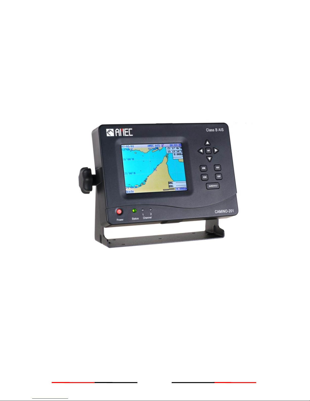
4.2 DISP (Display Modes Selection) ................................................................................25
4.3 DIM (Dimmer for Display Brightness Control)..........................................................30
4.4 Arrow Keys..................................................................................................................30
4.5 Menu Key.....................................................................................................................31
4.6 Menu Tree Structure ...................................................................................................34
5 MENU KEY NAVIGATION...............................................................................35
5.1 AIS Message List.........................................................................................................35
5.1.1 Inbox (Received SRM)..............................................................................................35
5.1.2 Outbox (Transmitted SRM).....................................................................................36
5.1.3 SRM Editting..............................................................................................................38
5.2 AIS Target Status.........................................................................................................39
5.2.1 Own Ship Information Settings..............................................................................40
5.2.2 AIS Target List and Friend Ships...........................................................................42
5.2.3 Region List and Setting...........................................................................................43
5.2.4 Ship Index and Individual Vessel Information ....................................................46
5.2.5 Product Version and Information ..........................................................................47
5.3 Ship Configuration and Setting.................................................................................48
5.3.1 Own Ship Static Data (User Password Protected) .............................................48
5.3.2 Friend Ship Editing...................................................................................................50
5.4 Transceiver ON / OFF Settings ..................................................................................52
5.5 System Configuration.................................................................................................53
5.5.1 Customizing System................................................................................................53
5.5.2 Radar View Reference Point Setting.....................................................................55
5.5.3 Factory Default Configuration (User Password Protected) .............................56
5.5.4 Output Port Baud Rate Settings............................................................................57
5.6 System Initialization ...................................................................................................58
5.6.1 Password Setting......................................................................................................58
5.6.2 MMSI Editting ............................................................................................................59
5.6.3 CPA/TCPA Settings (User Password Protected).................................................61
5.7 Dangerous Targets Information.................................................................................62
6 DISPLAY MODE..............................................................................................63
6.1 Radar View...................................................................................................................63
6.1.1 AIS Target Symbol Descriptions............................................................................64
6.1.2 Radar View Descriptions.........................................................................................66
6.2 Coastline Map Mode ...................................................................................................69

VI
7 APPENDIX .......................................................................................................70
7.1 Product Specifications...............................................................................................70
7.2 Dimensions..................................................................................................................73
7.3 Accessories.................................................................................................................75
7.4 Trouble Shooting ........................................................................................................75
7.4.1 Problem Analysis (By Status LED Indicator).......................................................75
7.4.2 Problem Analysis (Hardware).................................................................................76
7.4.3 Problem Analysis (Software)..................................................................................77
8 AMEC WORLD WIDE WARRANTY ...............................................................78
9 ABBREVIATIONS............................................................................................81
10 INDEX.............................................................................................................82

1
1 INTRODUCTION
1.1 CAMINO-201 Overview
The CAMINO-201 is a Class B AIS transponder using carrier-sense TDMA (CSTDMA)
technology. It is designed to inter-operable and compatible with Class A or other Class B
shipborne mobile AIS stations or any other AIS station operating on the AIS VHF data link.
CAMINO-201 AIS uses marine VHF channels with frequency set universally from 156.025 MHz
to 162.025 MHz. Having CAMINO-201 AIS on board, not only can you monitor the status of the
vessels in the surrounding area, but also receive the dynamic information (position, speed, SOG,
and etc.), static information (ship name, MMSI, call sign, and etc.), and voyage related
information (cargo type, destination, and etc.) from any vessels equipped withAIS.
CAMINO-201 AIS is one of the cutting-edge navigational aid equipment allowing real-time
information exchanges within AIS network. It is also capable of integrating with other maritime
systems such as Electronic Chart System (hereinafter called “ECS”) for various maritime
navigation applications.
CAMINO-201 is designed with 2 RF receivers and 1 RF transmitter. One of the RF receivers is
time-shared between AIS and DSC. At front side, CAMINO-201 equips with 5.7” LCD display

2
panel and 10 functional keypads. At rear side, CAMINO-201 equips with 1 VHF antenna
connector, 1 GPS antenna connector, 1 NMEA interface connector, 1 RS232 interface
connector, and 1 power connector.
*NOTE: The CAMINO-201 is an equipment to be used in protected environmental conditions. It
is not intended to expose to rain or spray longer than couple minutes.
1.2 Type of AIS
There are mainly two types of AIS transponder: Class A and Class B. The intended nature of
these AIS systems in navigations is different as illustrated in the following table. CAMINO-201 is
a Class B AIS transponder.
Table 1-2 Type of AIS
Class A AIS
‧Transmits and receives AIS signal in SOTDMAprotocols.
‧Intended for vessels meeting the IMOAIS carriage requirements.
‧It is mandatory for all commercial vessels that exceed 300 tons to be
equipped with Class AAIS.
Class B AIS
‧Transmits and receives AIS signal in CSTDMA protocols.
‧Not necessarily in accord with IMO AIS carriage requirements.
‧It is not mandatory for vessels to be equipped with Class B AIS.
‧Suitable for recreational vessels or fishing boats, in enhancing its safety at
sea.

3
1.3 AIS Message Type
The CAMINO-201 supports following message types.
Table 1-3 CAMINO-201 AIS message type
Type of Message
Data Details
Static Data
Maritime Mobile Service Identity number (“MMSI”)
Call sign and name
Type of ship
Length and beam
GPS Antenna location
Dynamic Data
Position of the vessel
Course Over Ground (hereinafter called “COG”)
Speed Over Ground (hereinafter called “SOG”)
Heading
Dynamic Reports
Speed of the ship
Status of the ship
SRM
Alarm
Safety
1.4 AIS Report Rate
The CAMINO-201 supports following report rate in accordance to ITU-R M.1371 and IEC
62287-1.
Table 1-4 CAMINO-201 AIS report rate
Platforms Condition
Nominal
Reporting Interval
Class B Ship-borne mobile equipment not moving faster than 2 knots
3 Minutes
Class B Ship-borne mobile equipment moving faster than 2 knots
30 Seconds
Report rate by command of VTS
5 Seconds highest

4
1.5 About This Manual
The manual contains installation instructions and operating information for CAMINO-201. While
most of the installation can be performed by the owner or the crew, a final commissioning can be
done by your local agent/dealer where needed or required. AMEC and the local agent/dealer will
not bear any responsibilities over any damages resulted in improper installation by unauthorized
agent/dealer.
1.6 Important Notice
The intended use of the AMEC CAMINO-201 AIS is to enhance the safety of vessels at sea.
However, a few points must be noted as below,
Any AIS cannot guarantee in monitoring and receiving signals from all vessels in the
surroundings unless those vessels equip with AIS device.
It is important to note that the AIS is designed for the purpose of anti-collision and is serves
as a compliment to navigation. It is not navigational equipment and does not replace any
navigational system installed on board.
Although AIS is operated automatically by itself, the owner or the crew on the vessel
should still maintain a proper lookout for the surroundings. While the AIS is capable of
setting alarm of Distance to Closest Point of Approach (hereinafter called “CPA”) and Time
to the Closest Point of Approach (hereinafter called “TCPA”), vessel owner or the crew
should be aware of the fact that there are vessels that are not equipped with AIS, and this
function will not apply on these vessels.
Incorrect data and information entered into theAIS is considered as erroneous information.
Erroneous information or improper configuration will cause risk to other vessels and the
own vessel when these information are transmitted. Users must be aware of this risk and
make sure that all the information entered into the system is correct and up to date.

5
WARNING
Warning
注意
2 INSTALLATION
2.1 General
The installation information for the CAMINO-201 is sub-divided into proper steps in block
diagrams for easy reference.
2.1.1 Safety Instructions
Before proceeding with installation, take note of the following safety instructions and read
through this installation manual carefully.
SAFETY INSTRUCTION
SAFETY INSTRUCTIONS
ELECTRICAL SHOCK HAZARD
Do not open the case of the
equipment. Only qualified
personnel could work on the
interior of the equipment.
WARNING
TURN OFF THE POWER BEFORE
PROCEEDING WITH INSTALLATION.
Proceeding with installation with the
power on could cause electrical shock or
fire.
AVOID INSTALLING THE EQUIPMENT
WHERE THERE IS DIRECT CONTACT
WITH RAIN OR SPLASHING WATER.
Electrical shock or fire could be resulted
if water leaks into the equipment.
FOLLOW THIS INSTRUCTION
MANUAL TO PROCEED WITH THE
INSTALLATION.
AMEC and your local agent/dealer will
not bear any responsibility of
equipment damage or personnel injury
due to improper installation.
Warning Label
A warning label (Figure 2-1-1) is
attached underneath the equipment.
Warranty of the equipment will be
invalid if this label is detached or
broken. AMEC and your local
agent/dealer will not bear any
responsibility of any damage to the
equipment, or damage in related to the
equipment, personnel injury, and etc.
Reject the equipment if this label is
detached or broken. Please contact
your local agent/dealer if this label is
missing.
MAKE SURE THE POWER SOURCE
AND THE POWER INPUT OF THE
EQUIPMENT ARE COMPATIBLE.
Damage to the equipment and fire could
be resulted if the power sources are not
correct. Please check the correct power
input on the adaptor.
Figure 2-1-1 Warning label
Name: Warning Label
No Warranty if this label
is detached or broken.
保固撕毁无效

6
2.1.2 Unpacking and Handling the Unit
2.1.3 Items in the Package
The CAMINO-201 is typically delivered with standard package as shown in Table 2-1-3. It is
also illustrated in Figure 2-1-3 (except manual).
Table 2-1-3 Standard equipment list
No.
Description
Product Code
Qty
1
CAMINO-201Class B AIS main unit
CAMINO-201
1
2
Manual
AIS-MNL-B201-E
1
3
Installation Kit
Power cable, 1m (3A)
M-ACC-CAB-AL-006
1
NMEA0183 interface cable, 1.5m
ACC-CAB-001
1
RS-232 interface cable, 1.2m
ACC-CAB-002
1
Knob
ASM-KNB-AISCLB01
2
Mounting bracket with buckle tenons
ASM-CRU-AISCLB01
1
Washer
ACC-WHR-001
2
Spring washer
ACC-WHR-002
2
M8 Screws
ACC-SRW-001
4
*NOTE:
(1) AMEC would not be able to fully ensure overall product performance if longer cable length
other than the specified length is used.
(2) If an extension power cable is required, use large gauge cable to minimize voltage drops.
Unpack the
product on a flat
and level surface.
Move and handle
with cautious. Do
not drop or bump.
Unpack the box
with the “this side
up” sign facing up.
Visual inspection
should be taken on
the box to see if it is
intact.
Take extra caution
if requiring sharp
object to unpack.
1
2
3
4
5
6
After unpacked,
check if all the
accessories and
unit are included.

7
Figure 2-1-3 Package items
2.2 Installation Procedure
2.2.1 Installation Precautions
Do not place or
install the
equipment near
any generator or
engine.
5
Do not place or
install the
equipment
beneath or near
any container that
filled with water or
liquid.
3
Do not place or
install the
equipment where
it is easily tripped,
stepped on, or
kicked at.
4
Installation should
proceed in a safe
environment and
does not have
direct contact with
rain or splashing
water.
1
When installation is
completed, please
remember to key in
own ship‟s MMSI
data and related
information through
keypad.
6
If it is required to
use a ladder to
install the
equipment, take
extra caution and
be careful of
falling down.
2
1. CAMINO-201 x1
2. Mounting Bracket x1
3. Knob x2
4. Washer x2
5. Spring Washer x2
6. M8 Screws x4
7. Power Cable x1
8. Interface Cable
(NMEA0183) x1
9. Interface Cable
(RS-232) x1
1.
3.
4.
5.
7.
2.
8.
6.
9.

8
2.2.2 Step by Step Installation Instructions
AMEC CAMINO-201 can be installed and mounted on flat surface, or it can be hung on the
ceiling or wall as shown below.
Figure 2-2-2-1 Installation overview
Table Stand Mounting
Ceiling or Wall Mounting

9
The installation procedure is graphically illustrated in the following steps.
Use the 4 M8 screws
provided to secure the
mounting brackets at the
4 holes marked .
I. Installation Instructions
Step 2:
1
2
3
Step 1:
Place the mounting
bracket on the desired
spot for installing
the CAMINO-201 .
(Refer to Figure 2-2-2-2 )
*NOTE:
6
1
Secure the mounting
bracket first before
mounting
CAMINO-201 .
Figure 2-2-2-2 Installation instruction
1
6
3
2

10
4
Table Stand Mounting:
The Display Panel of the
CAMINO-201 and
the Front Edge of the mounting
bracket should be on the same
side.
Ceiling Mounting:
The Display Panel of the
CAMINO-201 and
the Back Edge of the mounting
bracket should be on the same
side.
Wall Mounting:
The Display Panel of the
CAMINO-201 should face forward,
and the front edge of the mounting
bracket should face down.
*NOTE:
For faster and easier installation,
the Buckle Tenon for angle
adjustment has fixed on the body
joint .
(Refer to Figure 2-2-2-4)
6
5
Step 3:
Align the mounting bracket joint
on the CAMINO-201 with the
body joint on the mounting
bracket, and mount the
CAMINO-201 onto the mounting
bracket(Refer Figure 2-2-2-3)
5
6
Figure 2-2-2-3 Installation instruction
7
7
4
Figure 2-2-2-4 Installation instruction
4

11
10
8
II. Interface Connection
9
5
When the mounting bracket and the CAMINO-201 are aligned, insert the
knob thru the Spring Washer , the Washer , then the body joint
till it click on the mounting bracket joint as shown in Figure 2-2-2-5.
Step 4:
8
9
5
Step 5:
‧Knob should be placed outside of the body joint .
‧Spring Washer and Washer should be placed outside of the body
joint in the order as shown in Figure 2-2-2-5.
8
4
9
10
Step 6:
Tighten up the Knob to fix the angle of the CAMINO-201.
Loosen the Knob to adjust the angle of the CAMINO-201
(Refer to Figure 2-2-2-5)
8
Figure 2-2-2-5 Installation instruction
4
4
8
4

12
*NOTE: CAMINO-201 SUPPLIES ONLY 3.3V FOR GPS ANTENNA. DO NOT CONNECT A5V
GPS ANTENNA TO CAMINO-201 AS IT WOULD CAUSE SIGNIFICANT DAMAGE
TO THE EQUIPMENTAND THE ANTENNA. WE RECOMMEND YOU TO USE AMEC
GPS ANTENNA WITH CAMINO-201.
Step 2:
Step 5:
Step 3:
Step 1:
2
4
6
5
3
Connect the GPS cable to the
GPS ANT connector .*
Connect the VHF cable to the
VHF ANT connector .
2
Connect other NMEA0183
compatible system to the
NMEAinterface .
3
5
Figure 2-2-2-6 Installation instruction
Step 4:
Connect the computer to the
RS-232 interface if needed.
6
1
Connect the Power cable to
the Power connector .
4

13
2.2.3 Connector Pin Definition and Wiring
2.2.3.1 Power Connector
Ared wire and a black wire are included in the power cable.
Table 2-2-3-1 Power wiring details
PIN
WIRE COLOR
NAME
FUNCTION
1
Red
PWR
Positive (+), the input should be 12V / 24V DC
2
/
/
/
3
Black
GND
Power ground
2.2.3.2 NMEA 0183 Connector
The NMEA 0183 interface cable contains 12 different wires. Refer to the following table for the
wiring details.
Table 2-2-3-2 NEMA 0183 wiring details
PIN
COLOR
NAME
FUNCTION
1
Brown
RXP
Positive (+); CAMINO-201 receives external NMEA 0183
device information.
2
Blue
RXN
Negative (-); CAMINO-201 receives external NMEA 0183
device information.
3
White
TXP
Positive (+); Transmit AIS information.
4
Green
TXN
Negative (-); Transmit AIS information.
5
Yellow
/
/
6
Gray
/
/
7
Pink
/
/
8
Red
/
/
9
Black
/
/
10
Orange
ALMB
Alarm output
11
Purple
ALMA
Alarm input
12
Light Green
/
/

14
NMEA 0183 Wiring
Refer to the following wiring method for the external NMEAdevice with NMEA0183 interface or
RS-422.
*NOTE: Please make sure the external device is fully NMEA0183 compiled.
2.2.3.3 RS-232 Connector
RS-232 Connector contains 9 different wires. Refer to the following table for the wiring details.
Table 2-2-3-3 RS-232 wiring details
RS-232 Wiring
Refer to the following wiring method for the external RS-232 device with RS-232 interface.
NO.
NAME
FUNCTION
1
/
/
2
RX
Receive Data
3
TX
Transmit Data
4
/
/
5
GND
Power Ground
6
/
/
7
/
/
8
/
/
9
/
/
TXP
TXN
RXP
RXN
RXP
RXN
TXP
TXN
Figure 2-2-3-2 NMEA 0183 connections
CAMINO-201 NMEA 0183
External NMEA device
RX
TX
GND
TX
RX
GND
CAMINO-201 RS-232
PC RS-232
Figure 2-2-3-3 Connecting to PC via RS-232
Table of contents
Other AMEC Marine Radio manuals

AMEC
AMEC CAMINO-701 User manual

AMEC
AMEC WideLink B600W User manual

AMEC
AMEC WideLink B600S User manual

AMEC
AMEC WideLink B600 User manual

AMEC
AMEC MANDO-301 User manual

AMEC
AMEC Camino-101 Class B AIS User manual

AMEC
AMEC CAMINO-701 User manual

AMEC
AMEC Camino-108 User manual

AMEC
AMEC Camino-101 Class B AIS User manual

AMEC
AMEC CAMINO-701 User manual