
1999 Apr 22 5
NXP Semiconductors Product data sheet
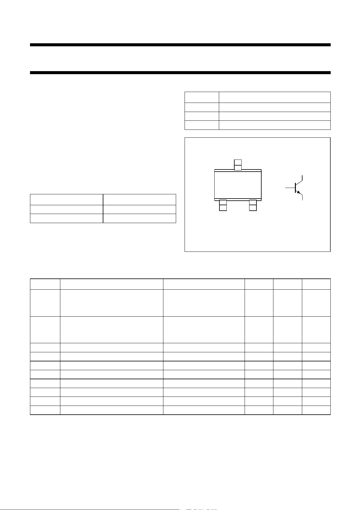
NPN general purpose transistors PMST6428; PMST6429
DATA SHEET STATUS
Notes
1. Please consult the most recently issued document before initiating or completing a design.
2. The product status of device(s) described in this document may have changed since this document was published
and may differ in case of multiple devices. The latest product status information is available on the Internet at
URL http://www.nxp.com.
DOCUMENT
STATUS(1) PRODUCT
STATUS(2) DEFINITION
Objective data sheet Development This document contains data from the objective specification for product
development.
Preliminary data sheet Qualification This document contains data from the preliminary specification.
Product data sheet Production This document contains the product specification.
DISCLAIMERS
General ⎯Information in this document is believed to be
accurate and reliable. However, NXP Semiconductors
does not give any representations or warranties,
expressed or implied, as to the accuracy or completeness
of such information and shall have no liability for the
consequences of use of such information.
Right to make changes ⎯NXP Semiconductors
reserves the right to make changes to information
published in this document, including without limitation
specifications and product descriptions, at any time and
withoutnotice.Thisdocumentsupersedes andreplacesall
information supplied prior to the publication hereof.
Suitability for use ⎯ NXP Semiconductors products are
not designed, authorized or warranted to be suitable for
use in medical, military, aircraft, space or life support
equipment, nor in applications wherefailureormalfunction
of an NXP Semiconductors product can reasonably be
expected to result in personal injury, death or severe
property or environmental damage. NXP Semiconductors
accepts no liability for inclusion and/or use of NXP
Semiconductors products in such equipment or
applications and therefore such inclusion and/or use is at
the customer’s own risk.
Applications ⎯Applicationsthat aredescribedhereinfor
any of these products are for illustrative purposes only.
NXP Semiconductors makes no representation or
warranty that such applications will be suitable for the
specified use without further testing or modification.
Limiting values ⎯Stress above one or more limiting
values (as defined in the Absolute Maximum Ratings
System of IEC 60134) may cause permanent damage to
the device. Limiting values are stress ratings only and
operation of the device at these or any other conditions
above those given in the Characteristics sections of this
document is not implied. Exposure to limiting values for
extended periods may affect device reliability.
Terms and conditions of sale ⎯NXP Semiconductors
products are sold subject to the general terms and
conditions of commercial sale, as published at
http://www.nxp.com/profile/terms, including those
pertaining to warranty, intellectual property rights
infringement and limitation of liability, unless explicitly
otherwise agreed to in writing by NXP Semiconductors. In
case of any inconsistency or conflict between information
in this document and such terms and conditions, the latter
will prevail.
No offer to sell or license ⎯Nothing in this document
maybe interpretedor construed asanoffer tosellproducts
that is open for acceptance or the grant, conveyance or
implication of any license under any copyrights, patents or
other industrial or intellectual property rights.
Export control ⎯This document as well as the item(s)
described herein may be subject to export control
regulations.Exportmightrequireapriorauthorizationfrom
national authorities.
Quick reference data ⎯The Quick reference data is an
extract of the product data given in the Limiting valuesand
Characteristics sections of this document, and as such is
not complete, exhaustive or legally binding.


 Specification sheet")


