5
RISQUES
EN CAS DE MAUV
AISE UTILISA
TION DU MATERIAL
Consignes
générales de sécurité
toute
utilisation anormale de l’appareil du pulvérisation ou des
accessoires comme, par exemple, la mise sous une pression
excessive, les modifications de pièces, l’utilisation de produits
chimiques et de matières incompatibles et l’utilisation de
pièces usées ou abîmées peut causer des dégâts à l’appareil
ou des ruptures de pièces et entraîner une injection de liquide
ou d‘autres blessures sérieuses, un incendie, une explosion
ou d’autres dégâts.
T
oujours porter une protection pour les yeux, de gants, des
vêtements protecteur et un dispositif pour la respiration cor
-
respondant aux recommandations des fabricants de fluides et
solvants.
Pression
Ce pulvérisateur peut produire une
PRESSION MAXIMUM
DE TRAV
AIL 210 bar (3000 lb/po.
@
).
S’assurer que tous les
éléments du pulvérisateur et ses accessoires sont conçus
pour résister à la pression maximum de travail de ce pulvéri
-
sateur. NE P
AS dépasser la pression maximum de travail
d’aucun des éléments ou accessoires utilisés avec cet appa
-
reil.
Compatibilité
chimique des corps
BIEN S’ASSURER que tous les corps des solvants utilisés
sont chimiquement compatibles avec les parties mouillées
indiquées dans les “Données techniques”, à page 43. T
ou-
jours lire soigneusement les documents et brochures du fabri
-
cant des fluides et solvants utilisés avant de s’en servir dans
ce
pulvérisateur.
Le fluide à haute pression circulant dans les tuyaux peut être
très dangereux. En cas de fuite sur le tuyau, de fissure, déchi
-
rure ou rupture à la suite de l’usure, de dégâts ou d’une mau
-
vaise utilisation, les projections de fluide haute pression qui
en proviennent peuvent entraîner des blessures graves par
pénétration sous la peau ou par contact, ainsi que des dégâts
matériels.
TOUS
LES TUY
AUX FLEXIBLES DOIVENT A
VOIR DES
RESSORTS SPIRALE DE PROTECTION AUX 2 BOUTS!
Les spirales de protection contribuent à éviter la formation de
pliures, de boucles ou de nœuds sur les tuyaux qui pourraient
entraîner la rupture du tuyau à l’endroit du raccord ou à son
voisinage.
SERRER
FERMEMENT tous les raccords avant chaque utili
-
sation. Le fluide sous pression peut faire sauter un raccord
desserré ou produire un jet à haute pression s’échappant par
le raccord.
NE JAMAIS utiliser un tuyau endommagé. NE P
AS essayer
de refaire le raccord d’un tuyau haute pression ni de réparer
le tuyau avec du ruban adhésif ou par tout autre moyen. Un
tuyau réparé ne peut pas résister au fluide sous pression.
MANIPULER LES TUYAUX AVEC PRECAUTION ET CHOI-
SIR SOIGNEUSEMENT LEUR CHEMIN. Ne pas déplacer le
fluide en tirant sur le tuyau. Ne pas utiliser de fluides ou de
solvants que ne sont pas compatibles avec l’enveloppe inté
-
rieur ou extérieure de tuyau. NE P
AS exposer le tuyau à flui
-
des des températures supérieures à 82
_
C (180
_
F) ou infé
-
rieures à –40
_
C (–40
_F).
Continuité
de la mise à la terre des tuyaux
Une
bonne continuité de la mise à la terre des tuyaux est es
-
sentielle pour maintenir la mise à la terre de l’ensemble de
vaporisation. Vérifiez la résistance électrique de vos tuyaux à
fluides et à air
, au moines une fois par semaine. Si votre
tuyau ne comporte pas d’étiquette qui précise la résistance
électrique maximum, prenez contact avec le fournisseur de
tuyaux ou la fabricant pour avoir les limites de résistance
maximum. Utilisez un mètre de résistance de la gamme ap
-
propriée pour votre tuyau et vérifiez la résistance. Si celle–ci
dépasse les limites recommandées, remplacez le tuyau im
-
médiatement. Un tuyau sans mise à la terre ou avec une mise
à la terre incorrecte peut entraîner des risques pour votre sys
-
tème. Lisez aussi
LES RISQUES D’INCENDIE OU D’EX-
PLOSION.
RISQUES
D’INCENDIE OU D’EXPLOSION
De
l’électricité statique est produite par le passage du fluide à
grande vitesse dans la pompe et dans les tuyaux. Si toutes
les pièces de l’appareil de pulvérisation ne sont pas convena
-
blement reliées ou à la masse ou à la terre, des étincelles
peuvent se produire et l’appareil risques d’être dangereux.
Des étincelles peuvent Également se produire à l’occasion du
branchement ou du débranchement du cordon d’alimentation
ou de l’utilisation d’un moteur à essence. Les étincelles sont
suf
fisantes pour allumer les vapeurs de solvants et le fluide
pulvérisé, les fines particules de poussière ainsi que d’autres
substances inflammables, quand on pulvérisé à l’intérieur ou
à l’extérieur
, et elles peuvent causer un incendie ou une ex
-
plosion, ainsi que des blessures graves et des dégâts maté
-
riels. T
oujours brancher le pulvérisateur dans une prise se
trouvant à au moins 6 m (20 pieds) de l’appareil et de l’endroit
où se fait la pulvérisation. Ne pas brancher ou débrancher un
cordon d’alimentation quel qu’il soit dans la zone où se fait la
pulvérisation quand il y a le moindre risque que ds vapeurs
encore présentes dans l’air prennent feu.
S’il se produit des étincelles d’électricité statique, ou si vous
ressentez la moindre décharge, ARRETEZ IMMEDIA
TE-
MENT LA PULVERISA
TION. Vérifiez que le système avant
que le problème soit identifié et corrigé.
Mise
à la terre ou à la masse
Pour
réduire les risques de production d’étincelles d’électricité
statique, le pulvérisateur et tous les équipement utilisés ou se
trouvant dans la zone de pulvérisation doivent être reliés à la
terre ou à la masse. Pour connaître le détail des instructions
de mise à la terre dans la région et le type particulier d’équi
-
pement, CONSUL
TER le code ou les réglementations électri
-
ques locales. S’ASSURER que tous le équipements de pulvé
-
risation suivants sont bien reliés à la terre:
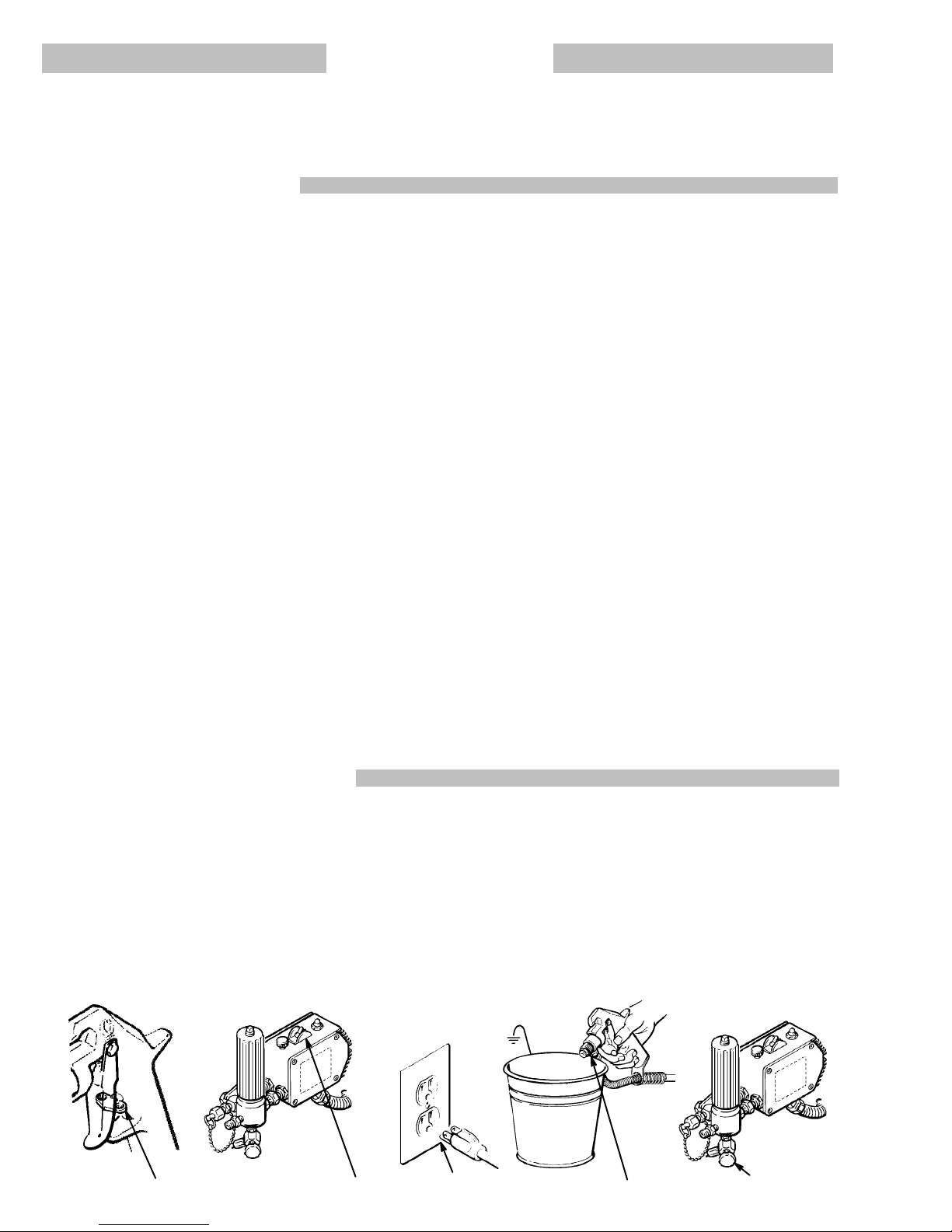
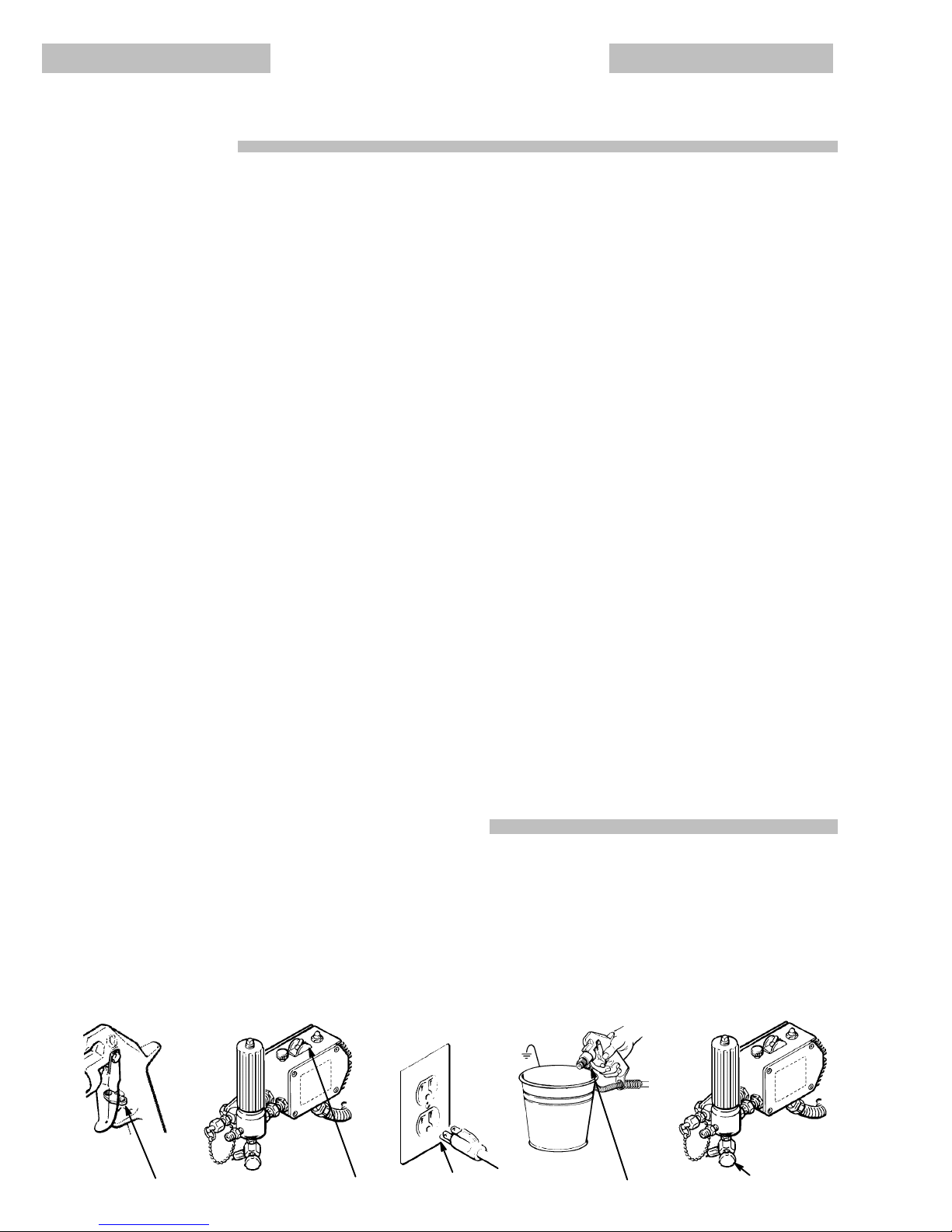
1.
Pulvérisateur:
Brancher le cordon d’alimentation ou la
rallonge
qui doivent être équipes d’une prise à 3 fiches en bon
état,
dans une prise de courant convenablement mis à la ter
-
re. Ne pas utiliser d’adapteur . Toutes les rallonges doivent
avoir
3 fils et être prévues pour 15 ampères.
2.
Pistolet:
Réaliser la mise à la terre en le raccordant à une
tuyau
flexible et à une pulvérisateur déjà convenablement re
-
liés
à la terre.
3.
Tuyaux flexibles:
Afin d’assurer la continuité de la mise à la
terre,
n’utiliser que des tuyaux comportant une mise à la
terre
et ayant une longueur maximum combinée de 150 m (1500
pieds). Se reporter également au paragraphe, “Continuité
du
circuit de mis à la terre des tuyaux”.
4.
Récipient
d’alimentation:
observer le code
ou les réglementa
-
tions
locales.
5.
Objets,
matériel ou surfaces recevant la pulvérisation:
obser
-
ver
le code ou les réglementations locales.
6.
Tous
le seaux de solvant
utilisés pour le rinçage: observer le
code
ou les réglementations
locales.
N’utiliser que des seaux
métallique
conducteurs de l’électricité. Ne pas mettre le seau
sur
une surface non
conductrice comme sur du papier ou du
carton
car cela interromprait la continuité de la mise à la terre.
7.
Pour
conserver la continuité de la mise à la terre quand on rin
-
cé
le
matériel ou quand on libère la pression,
toujours mainte
-
nir
une
partie métallique du pistolet fermement appuyée con
-
tre
le côté d’un
seau
en métal
puis appuyer sur la détente du
pistolet.
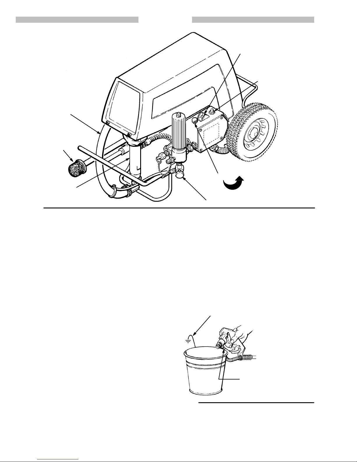
Mesures
de Sécurité concernant le Rinçage
Pour
réduire les risques de blessures par pénétration de la
peau et les risques dûs aux étincelles d’électricité statique ou
aux éclaboussures, observe la marche à suivre pour le rinça
-
ge donnée à la page 12 de ce manuel.