Observator OMC-116 User manual

OMC-116 Installation manual
V1.02 January 2015
TDC-HB
OBSERVATOR
instruments

TDC –HB 06-01-2015 OMC-116 installation manual page 2 of 11
OBSERVATOR
instruments
OMC-116
Installation manual
Revision History
V1.01 August 2012 First release
V1.02 January 2015 - Revised connection board.
- OMC-116-M
- Heated Bracket option

TDC –HB 06-01-2015 OMC-116 installation manual page 3 of 11
OBSERVATOR
instruments
OMC-116
Installation manual
Introduction
This manual describes the installation of the OMC-116 ultrasonic wind sensor.
Installation must be carried out by a qualified engineer. This manual assumes the engineer
has basic knowledge of electronics. We recommend reading this manual before installation
of the sensor.

TDC –HB 06-01-2015 OMC-116 installation manual page 4 of 11
OBSERVATOR
instruments
OMC-116
Installation manual
Pre installation notes & requirements
The OMC-116 can’t be directly powered by an Obsermet display (like OMC-138/139) or data
collection unit (like the OMC-183/184). A separate power supply is required:
12 -15Vdc 1A when no heating is required
24Vdc 10A when sensor heating is required
The heating is temperature and voltage controlled, do not use a 24V
power supply <10 A.
Recommended cabling:
Without heating (12-15Vdc): 2x2x0.75 mm2 shielded
With heating (24Vdc, 10A): 2x2.5mm2 ( power, max 30m)* + 2x0.75mm2 shielded
*The heating will not be operated if the voltage is below 20V. Especially
when long cables are used check that the losses over the cable are
acceptable and the voltage at the sensor is well above 20V. Alternatively
the power supply unit must be placed closer to the sensor and/or thicker
cable or a power supply with a higher voltage must be used (voltage at
the sensor may not exceed 28V).
For Marine applications and locations with possible heavy vibrations
only the OMC-116-M should be used! This model is specific designed to
withstand heavy vibrations and is tested to DNV 2.4 environmental
vibration class C specifications.

TDC –HB 06-01-2015 OMC-116 installation manual page 5 of 11
OBSERVATOR
instruments
OMC-116
Installation manual
Terminals
Sensor connections pre 2015
1. Ground (power)
2. Power (+12 .. 28 VDC)
3. NMEA 0183 B (RS422/485)
4. NMEA 0183 A (RS422/485)
5. Analogue ground
6. Analogue Wind Speed (optional)
7. Analogue ground
8. Analogue Wind direction (optional)
Sensor connection from 2015
1. Ground (power)
2. Power (+12 .. 28 VDC)
3. NMEA 0183 B (RS422/485)
4. NMEA 0183 A (RS422/485)
5. Analogue ground Wind Speed & Direction
6. Analogue Wind Speed (optional)
7. Control
8. Analogue Wind direction (optional)
Output is either NMEA or Analogue.

TDC –HB 06-01-2015 OMC-116 installation manual page 6 of 11
OBSERVATOR
instruments
OMC-116
Installation manual
Sensor installation
The OMC-116 must be mounted on top of a mast
(Ø 45 .. 60mm) with the included U bolts.
Make sure the sensor is free of obstacles.
Recommended sensor height is 10m. Wind speed should be
measured at 10m height however an obstacle free environment
is more important.
Bracket & U-bolt must make contact with metal of the mast to lead any static
discharge to ground. If this is not possible due to coating etc. a proper earth lead
must be connected to 1 of the U-bolts.
The mast must be correctly earthed to regulations.
Cable connection
The shield of the cable(s) may not be laid to ground on the receiving (display /
signal conditioning) side of the cable but must be connected on sensor side.
The junction box does have an extra (plugged) M20 hole in case separate cables are used
for signal and power.
Alignment
The sensor must be lined up to North (fixed applications) or for ship applications to the bow
of the vessel.
The OMC-116 has several markings indicating the North / Bow
direction of the sensor:
1. Arrow on top
2. Small arrow on sensor deck
3. Drilling hole visible from below
4. Front junction box

TDC –HB 06-01-2015 OMC-116 installation manual page 7 of 11
OBSERVATOR
instruments
OMC-116
Installation manual
NMEA output
The OMC-116 sensor outputs a MWV message once a second at 4800 baud:
$IIMWV,xxx.x,R,xxx.x,M,A*xx(CR)(LF)
$IIMWV, ID : II, MWV message type
xxx.x, Wind direction
R, Relative
xxx.x, Wind speed
M, m/s
A, A=valid value, V= invalid value
* Check sum identifier
xx Check sum (high byte first)
CR Carriage Return
LF Line Feed

TDC –HB 06-01-2015 OMC-116 installation manual page 8 of 11
OBSERVATOR
instruments
OMC-116
Installation manual
Specifications
Power supply: 24 .. 28 Vdc (240W)
12 .. 15 Vdc if no heating is used (15W)
Power consumption: +/- 1.8W/h (without heating)
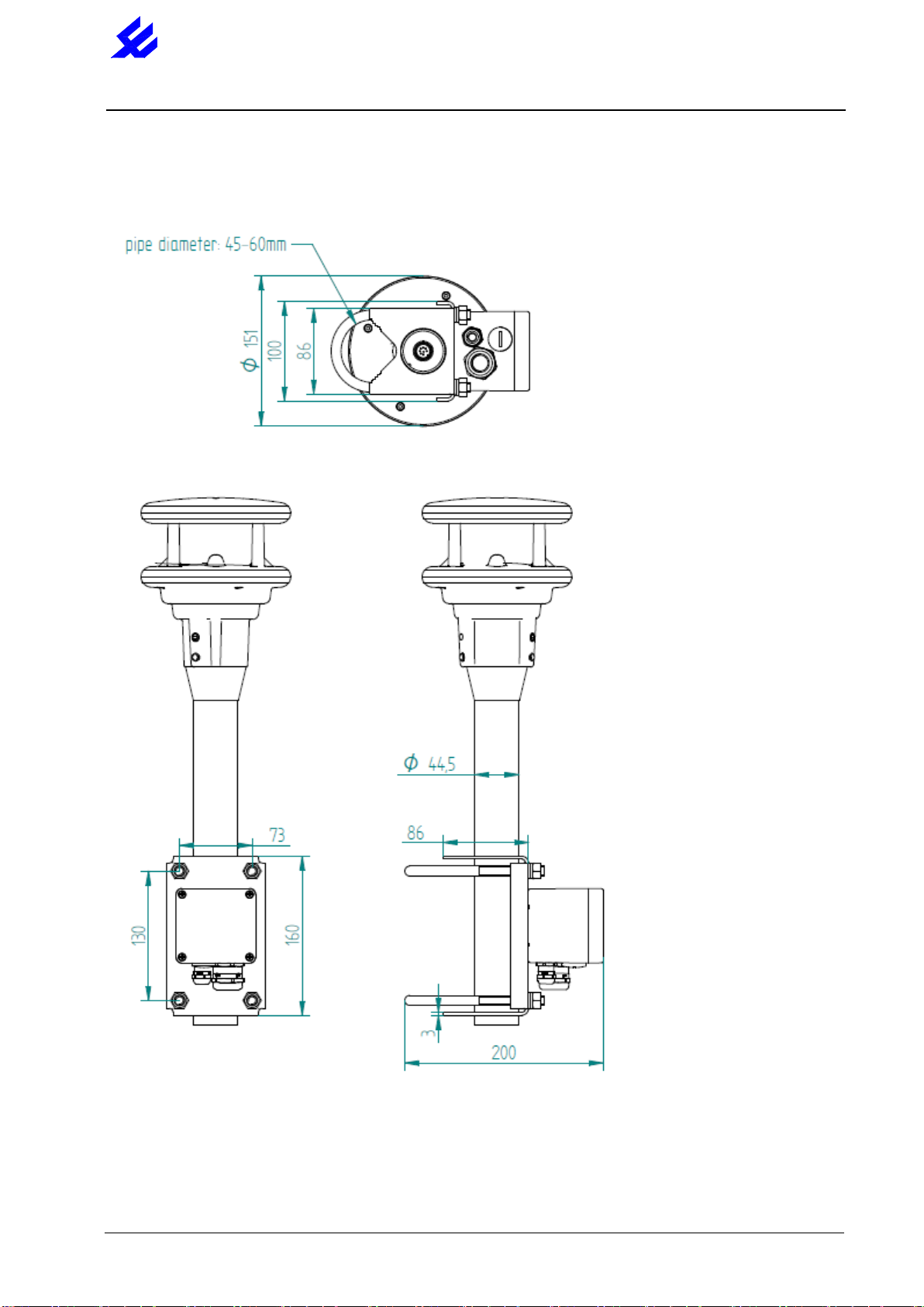
Weight (incl. U bolts): 4.3 kg
Fastening: U-bolts on top of mast Ø 45 .. 60 mm
Protection class: III (SELV)
Protection type: IP66
Storage conditions
Permissible storage temperature: -55°C ... +80°C
Permissible relative humidity: 0 ... 95% RH Non-condensing
Operating conditions
Permissible operating temperature: -40°C ... +60°C (with heating)
Permissible operating temperature: -20°C ... +60°C (without heating)
Permissible relative humidity: 0 ... 100% RH
Output: RS422/485 NMEA (MWV once a second)
Baud rate 4800 (others on request)
NMEA ID: II (others on request)
Analogue (4-20mA, voltage) Optional
Housing: Powder coated Seawater-resistant aluminum AlMg3Si
(Bracket RVS)
Measurement process: Ultrasound
Measuring range wind speed: 0 –75m/s
Resolution wind speed: 0.1m/s
Accuracy wind speed: ±0,2 m/s or ±2% RMS (the higher value)
Measuring range wind direction: 0 –359.9°
Resolution wind direction: 0.1°
Accuracy wind direction: < 2° (> 1m/s) RMSE
Response threshold: 0.1 m/s
Sampling rate: 1 second

TDC –HB 06-01-2015 OMC-116 installation manual page 9 of 11
OBSERVATOR
instruments
OMC-116
Installation manual
Dimensions

TDC –HB 06-01-2015 OMC-116 installation manual page 10 of 11
OBSERVATOR
instruments
OMC-116
Installation manual
OMC-116-M

TDC –HB 06-01-2015 OMC-116 installation manual page 11 of 11
OBSERVATOR
instruments
OMC-116
Installation manual
Disposal
Within the EC
The device must be disposed of in accordance with European Directives 2002/96/EC
and 2003/108/EC (waste electrical and electronic equipment). Waste equipment must
not be disposed of as household waste! For environmentally sound recycling and the
disposal of your waste equipment please contact a certified electronic waste disposal
company.
Outside the EC
Please comply with the applicable regulations for the proper disposal of waste
electrical and electronic equipment in your respective country.
Repair / Corrective Maintenance
Please arrange for any faulty equipment to be checked and, if necessary, repaired by the
manufacturer exclusively. Do not open the equipment and do not under any circumstances
attempt to carry out your own repairs.
Contact your local dealer or Observator instruments:
Service@observator.com
Other Observator Accessories manuals
Popular Accessories manuals by other brands

AKCP
AKCP IO-digital8 user manual

ROSE DISPLAYS
ROSE DISPLAYS SNAIL ADHESIVE-GENERIC installation instructions

Pool Shot
Pool Shot PSM-100 Assembly instructions

Maevi
Maevi ZigBee quick start guide

ekwb
ekwb EK-Momentum MSI Z390 MEG ACE installation manual

Energy Saving Sensors
Energy Saving Sensors HC-150W instruction manual